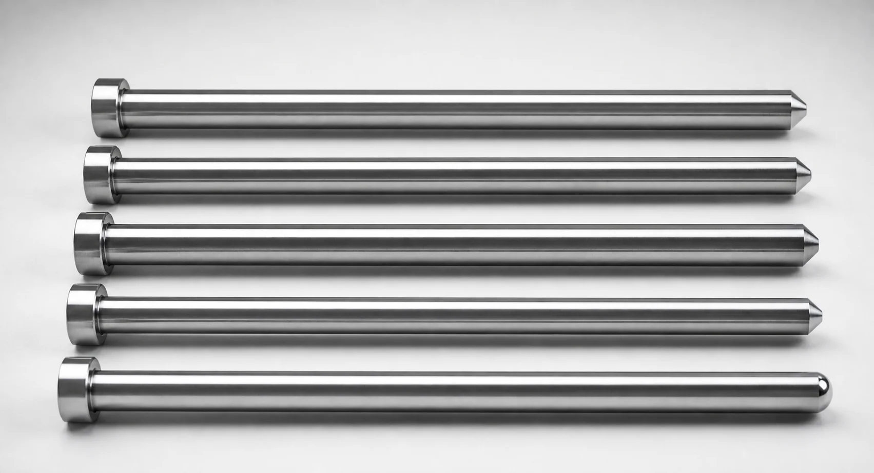
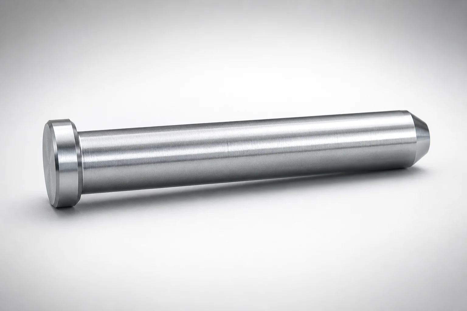
JIS Standard SKD61 Steel Straight Center Pins with Tip Processed
Straight Center Pins with Tip Processed (SKD61 steel) are engineered with a nitrided surface treatment to resist wear and maintain consistent positioning in high-load molding setups. Built for reliable center guidance and repeatable assembly.
- Tip-processed straight geometry supports stable centering during die closure
- SKD61 steel with nitrided surface treatment improves corrosion and abrasion resistance
- Designed for H7 class ejector sleeve inner-diameter fit to help maintain alignment
- Manufactured to JIS standards for compatibility in precision mold assemblies
Specifications
130 configurations available
| Head Thickness | Shaft Diameter Tolerance | D/P (Shaft Diameter) (mm) | Tip Shape | No. (Nominal diameter) (mm) | C (C chamfering width on the tip) (mm) | K (Taper angle) (°) | L (L dimension) (mm) | R (Tip R chamfering) (mm) | S (Tip tapered width) (mm) | type |
|---|---|---|---|---|---|---|---|---|---|---|
| 6mm(JIS) | -0.01/-0.02 | 3.5 ~ 3.9 | B | 4 | - | - | 50 ~ 400 | - | - | - |
| 6mm(JIS) | -0.01/-0.02 | 4 ~ 4.4 | B | 4.5 | - | - | 50 ~ 400 | - | - | - |
| 6mm(JIS) | -0.01/-0.02 | 4.5 ~ 4.9 | B | 5 | - | - | 50 ~ 500 | - | - | - |
| 6mm(JIS) | -0.01/-0.02 | 5 ~ 5.4 | B | 5.5 | - | - | 50 ~ 500 | - | - | - |
| 6mm(JIS) | -0.01/-0.02 | 5.5 ~ 5.9 | B | 6 | - | - | 50 ~ 500 | - | - | - |
| 6mm(JIS) | -0.01/-0.02 | 6 ~ 6.4 | B | 6.5 | - | - | 50 ~ 500 | - | - | - |
| 6mm(JIS) | -0.01/-0.02 | 6.5 ~ 6.9 | B | 7 | - | - | 50 ~ 500 | - | - | - |
| 8mm(JIS) | -0.01/-0.02 | 7 ~ 7.9 | B | 8 | - | - | 50 ~ 500 | - | - | - |
| 8mm(JIS) | -0.01/-0.02 | 8 ~ 9.9 | B | 10 | - | - | 50 ~ 500 | - | - | - |
| 8mm(JIS) | -0.01/-0.02 | 10 ~ 11.9 | B | 12 | - | - | 50 ~ 500 | - | - | - |
| 8mm(JIS) | -0.01/-0.02 (Reference tolerance) | 12 ~ 14.9 | B | 15 | - | - | 50 ~ 500 | - | - | - |
| 8mm(JIS) | -0.01/-0.02 (Reference tolerance) | 15 ~ 15.9 | B | 16 | - | - | 50 ~ 500 | - | - | - |
| 6mm(JIS) | -0.01/-0.02 | 3.5 ~ 3.9 | C | 4 | 0.1 ~ 1.9 | - | 50 ~ 400 | - | - | - |
| 6mm(JIS) | -0.01/-0.02 | 4 ~ 4.4 | C | 4.5 | 0.1 ~ 2.1 | - | 50 ~ 400 | - | - | - |
| 6mm(JIS) | -0.01/-0.02 | 4.5 ~ 4.9 | C | 5 | 0.1 ~ 2.4 | - | 50 ~ 500 | - | - | - |
| 6mm(JIS) | -0.01/-0.02 | 5 ~ 5.4 | C | 5.5 | 0.1 ~ 2.6 | - | 50 ~ 500 | - | - | - |
| 6mm(JIS) | -0.01/-0.02 | 5.5 ~ 5.9 | C | 6 | 0.1 ~ 2.9 | - | 50 ~ 500 | - | - | - |
| 6mm(JIS) | -0.01/-0.02 | 6 ~ 6.4 | C | 6.5 | 0.1 ~ 3.1 | - | 50 ~ 500 | - | - | - |
| 6mm(JIS) | -0.01/-0.02 | 6.5 ~ 6.9 | C | 7 | 0.1 ~ 3.4 | - | 50 ~ 500 | - | - | - |
| 8mm(JIS) | -0.01/-0.02 | 7 ~ 7.9 | C | 8 | 0.1 ~ 3.9 | - | 50 ~ 500 | - | - | - |
| 8mm(JIS) | -0.01/-0.02 | 8 ~ 9.9 | C | 10 | 0.1 ~ 4.9 | - | 50 ~ 500 | - | - | - |
| 8mm(JIS) | -0.01/-0.02 | 10 ~ 11.9 | C | 12 | 0.1 ~ 5.9 | - | 50 ~ 500 | - | - | - |
| 8mm(JIS) | -0.01/-0.02 (Reference tolerance) | 12 ~ 14.9 | C | 15 | 0.1 ~ 7.4 | - | 50 ~ 500 | - | - | - |
| 8mm(JIS) | -0.01/-0.02 (Reference tolerance) | 15 ~ 15.9 | C | 16 | 0.1 ~ 7.9 | - | 50 ~ 500 | - | - | - |
| 6mm(JIS) | -0.01/-0.02 | 3.5 ~ 3.9 | G | 4 | - | 45 ~ 89 | 50 ~ 400 | - | - | - |
| 6mm(JIS) | -0.01/-0.02 | 4 ~ 4.4 | G | 4.5 | - | 45 ~ 89 | 50 ~ 400 | - | - | - |
| 6mm(JIS) | -0.01/-0.02 | 4.5 ~ 4.9 | G | 5 | - | 45 ~ 89 | 50 ~ 500 | - | - | - |
| 6mm(JIS) | -0.01/-0.02 | 5 ~ 5.4 | G | 5.5 | - | 45 ~ 89 | 50 ~ 500 | - | - | - |
| 6mm(JIS) | -0.01/-0.02 | 5.5 ~ 5.9 | G | 6 | - | 45 ~ 89 | 50 ~ 500 | - | - | - |
| 6mm(JIS) | -0.01/-0.02 | 6 ~ 6.4 | G | 6.5 | - | 45 ~ 89 | 50 ~ 500 | - | - | - |
| 6mm(JIS) | -0.01/-0.02 | 6.5 ~ 6.9 | G | 7 | - | 45 ~ 89 | 50 ~ 500 | - | - | - |
| 8mm(JIS) | -0.01/-0.02 | 7 ~ 7.9 | G | 8 | - | 45 ~ 89 | 50 ~ 500 | - | - | - |
| 8mm(JIS) | -0.01/-0.02 | 8 ~ 9.9 | G | 10 | - | 45 ~ 89 | 50 ~ 500 | - | - | - |
| 8mm(JIS) | -0.01/-0.02 | 10 ~ 11.9 | G | 12 | - | 45 ~ 89 | 50 ~ 500 | - | - | - |
| 8mm(JIS) | -0.01/-0.02 (Reference tolerance) | 12 ~ 14.9 | G | 15 | - | 45 ~ 89 | 50 ~ 500 | - | - | - |
| 8mm(JIS) | -0.01/-0.02 (Reference tolerance) | 15 ~ 15.9 | G | 16 | - | 45 ~ 89 | 50 ~ 500 | - | - | - |
| 6mm(JIS) | -0.01/-0.02 | 3.5 ~ 3.9 | R | 4 | - | - | 50 ~ 400 | 0.2 ~ 1.9 | - | - |
| 6mm(JIS) | -0.01/-0.02 | 4 ~ 4.4 | R | 4.5 | - | - | 50 ~ 400 | 0.2 ~ 2.1 | - | - |
| 6mm(JIS) | -0.01/-0.02 | 4.5 ~ 4.9 | R | 5 | - | - | 50 ~ 500 | 0.2 ~ 2.4 | - | - |
| 6mm(JIS) | -0.01/-0.02 | 5 ~ 5.4 | R | 5.5 | - | - | 50 ~ 500 | 0.2 ~ 2.6 | - | - |
| 6mm(JIS) | -0.01/-0.02 | 5.5 ~ 5.9 | R | 6 | - | - | 50 ~ 500 | 0.2 ~ 2.9 | - | - |
| 6mm(JIS) | -0.01/-0.02 | 6 ~ 6.4 | R | 6.5 | - | - | 50 ~ 500 | 0.2 ~ 3.1 | - | - |
| 6mm(JIS) | -0.01/-0.02 | 6.5 ~ 6.9 | R | 7 | - | - | 50 ~ 500 | 0.2 ~ 3.4 | - | - |
| 8mm(JIS) | -0.01/-0.02 | 7 ~ 7.9 | R | 8 | - | - | 50 ~ 500 | 0.2 ~ 3.9 | - | - |
| 8mm(JIS) | -0.01/-0.02 | 8 ~ 9.9 | R | 10 | - | - | 50 ~ 500 | 0.2 ~ 4.9 | - | - |
| 8mm(JIS) | -0.01/-0.02 | 10 ~ 11.9 | R | 12 | - | - | 50 ~ 500 | 0.2 ~ 5.9 | - | - |
| 8mm(JIS) | -0.01/-0.02 (Reference tolerance) | 12 ~ 14.9 | R | 15 | - | - | 50 ~ 500 | 0.2 ~ 7.4 | - | - |
| 8mm(JIS) | -0.01/-0.02 (Reference tolerance) | 15 ~ 15.9 | R | 16 | - | - | 50 ~ 500 | 0.2 ~ 7.9 | - | - |
| 6mm(JIS) | -0.01/-0.02 | 3.5 ~ 3.9 | T | 4 | - | 1 ~ 45 | 50 ~ 400 | - | 0.1 ~ 8 | - |
| 6mm(JIS) | -0.01/-0.02 | 4 ~ 4.4 | T | 4.5 | - | 1 ~ 45 | 50 ~ 400 | - | 0.1 ~ 9 | - |
Product Guide
Application Scenarios+
These straight center pins with a tip-processed surface are used as alignment components in injection mold tooling, especially where repeatable die closure and positional guidance are critical. The nitrided wear-resistant surface helps the pin maintain its dimensional stability after repeated cycles, supporting consistent centering in the cavity during start-up and steady-state production.
- Automotive connector and terminal molds: The tip-processed straight geometry promotes stable centering as the dies close, reducing the risk of misalignment under high clamping loads and abrasive wear from polymer flow and venting debris.
- Electronics housings and precision enclosures: Designed for an H7 class ejector sleeve inner-diameter fit, the pin helps maintain coaxial alignment in die cavities where tight assembly tolerances affect part geometry.
- Die cast or insert-overmolding tooling (where guided cores are needed): The SKD61 base with a nitrided surface supports long-term guidance by improving abrasion resistance while keeping fit consistency in guided systems.
Tip processing and the specified fit class make this variant well-suited for precision mold assemblies requiring stable alignment and long service life.
Material & Process Details+
This product is made from JIS SKD61 steel, commonly selected for hot-work and mold tooling because it combines good toughness with wear resistance. The surface is nitrided, creating a hard, wear-resistant layer that improves abrasion resistance and supports consistent alignment during frequent die closures.
- Heat treatment state: The base material is in a mold-ready condition per SKD61 practice, followed by nitriding to form the strengthened surface layer.
- Hardness and performance trade-offs: Nitriding significantly increases surface hardness and wear resistance, while the core toughness helps reduce the risk of chipping compared to fully hardened, high-brittleness states.
- Wear vs. toughness: Compared with purely through-hardened approaches, nitriding emphasizes surface protection for longer guidance life while retaining a tougher interior.
Overall, SKD61 with nitrided surface treatment is suited for alignment pins exposed to repeated contact and sliding wear in mold cavities.
Sizing & Selection Guide+
Select the center pin dimensions by matching the pin’s shaft diameter and length to the mold’s guidance interface and required travel/engagement depth. The D/P (shaft diameter) range is 1.5 to 15 mm with reference shaft diameter tolerances of -0.01 / -0.02, and the no. (nominal diameter) range is 2 to 16 mm. For length, choose L = 50 to 400 mm (or up to 50 to 500 mm depending on the variant).
- Fit to ejector sleeve: This pin variant is intended for an H7 class ejector sleeve inner-diameter fit—ensure your sleeve ID and pin D/P select within the intended H7 compatibility.
- Tip geometry selection: Pick the tip shape (B, C, G, R, T) and tip features (e.g., C = 0.1 mm, R = 0.2 mm, S = 0.1 mm) to achieve the desired lead-in during die closure.
- Taper angle: Use the specified K range (45–89° or 1–45°) to tune engagement and centering behavior.
When in doubt, confirm the cavity/core alignment requirement and the sleeve ID that defines the H7 fit, then lock shaft diameter and overall length accordingly.
Frequently Asked Questions
Does this straight center pin rely on an H7 fit, and which diameter should I match in the mold assembly?+
Yes. The product is specified for an H7 class ejector sleeve inner-diameter fit to maintain alignment. In sizing, match the mold’s sleeve ID to the pin’s D/P (shaft diameter) (1.5 ~ 15 mm) while considering the reference shaft diameter tolerance of -0.01/-0.02.
What tip-processing options are available, and how do they affect die closure centering?+
Tip shape options include B, C, G, R, and T. The tip geometry is further defined by parameters such as C = 0.1 mm, R = 0.2 mm, S = 0.1 mm, and a taper angle K (45 ~ 89° or 1 ~ 45°). Selecting the correct tip shape and K helps control lead-in and centering behavior during die closure.
Which length range can I choose for different engagement depths, and what should I verify in the mold design?+
The L dimension is available from 50 to 400 mm, with an extended range up to 50 to 500 mm depending on the variant. Verify the required engagement depth for guidance without bottoming, and confirm that the pin length works with your stack-up and die travel.
How does nitriding on SKD61 influence wear performance compared to using only a hardened steel surface?+
The pin uses JIS SKD61 steel with a nitrided surface treatment. Nitriding improves wear resistance and helps maintain stable positioning over repeated cycles by protecting the contact surface. Compared with relying only on a fully through-hardened surface, the nitrided approach targets surface durability while retaining better core toughness.
What shaft diameter tolerances should I account for when selecting the pin for precision mold alignment?+
The reference shaft diameter tolerance is -0.01/-0.02. When designing for the intended H7 sleeve fit, ensure your mating sleeve ID and the selected pin D/P (1.5 ~ 15 mm) consider this tolerance to preserve the required clearance and alignment behavior.
Related Products
Need Custom Specifications?
Our engineering team can help with custom configurations, material selection, and volume pricing.