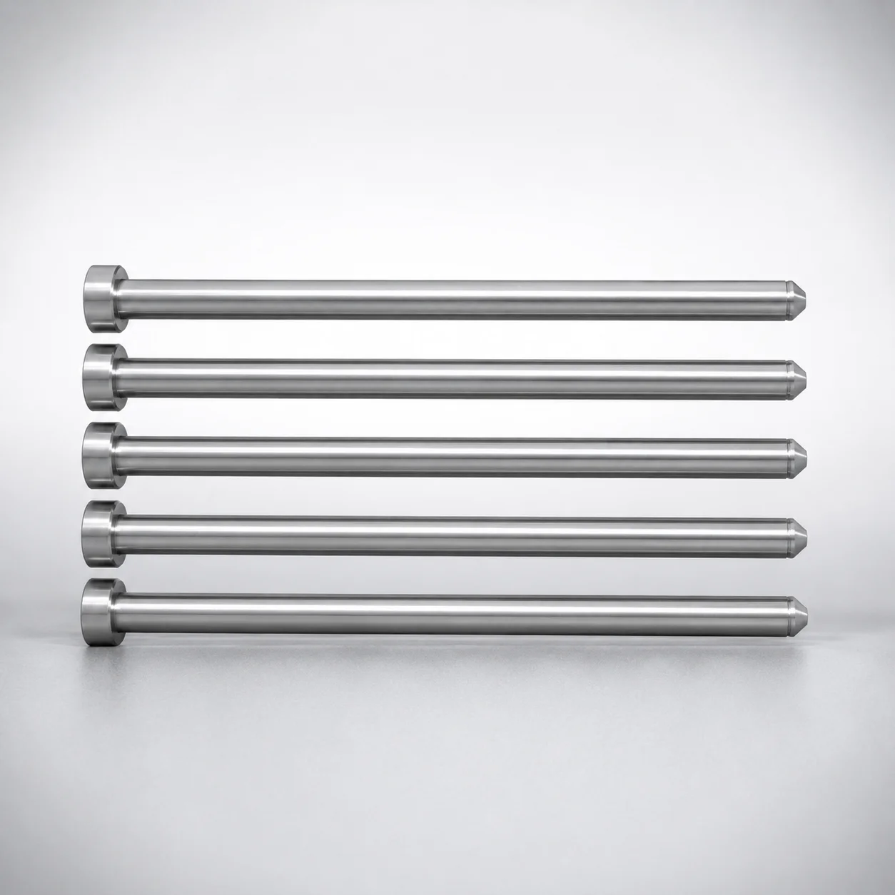
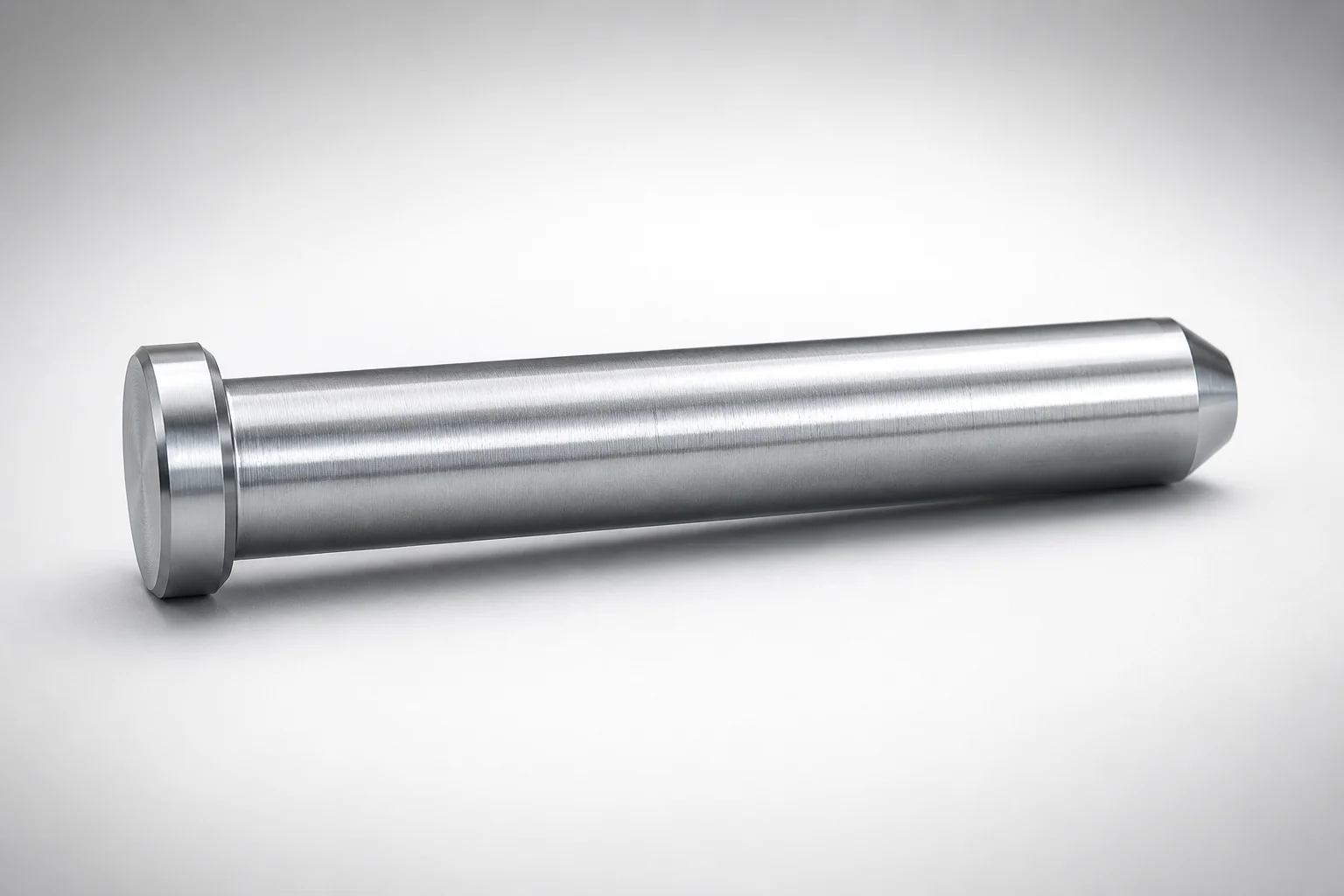
JIS Standard M2 Steel Straight Center Pins with Tip Processed
Straight Center Pins with Tip Processed (M2 steel) are made to support precise mold alignment and stable locating during repeated cycles. The processed tip design helps consistent engagement, while the JIS specification suits standard tooling setups.
- Tip-processed geometry for reliable center positioning and controlled engagement
- (M2 steel) construction with hardening-grade performance for wear resistance
- Designed for ejector sleeve bore fit, meeting H7/+0.01/0 compatibility
- JIS-standard pins suitable for center locating in injection molds
Specifications
280 configurations available
| Head Thickness | Shaft Diameter Tolerance | D/P (Shaft Diameter) (mm) | Tip Shape | Compatible Ejector Sleeve Inner Diameter Tolerance | C (C chamfering width on the tip) (mm) | K (Taper angle) (°) | L (L dimension) (mm) | R (Tip R chamfering) (mm) | S (Tip tapered width) (mm) | type |
|---|---|---|---|---|---|---|---|---|---|---|
| 4mm(T4) | 0/-0.005 | 1 | B | - | - | - | 50 ~ 200 | - | - | - |
| 4mm(T4) | 0/-0.005 | 1.5 | B | - | - | - | 50 ~ 250 | - | - | - |
| 4mm(T4) | 0/-0.005 | 2 | B | - | - | - | 50 ~ 250 | - | - | - |
| 4mm(T4) | 0/-0.005 | 2.5 | B | - | - | - | 50 ~ 250 | - | - | - |
| 4mm(T4) | 0/-0.005 | 3 | B | - | - | - | 50 ~ 300 | - | - | - |
| 4mm(T4) | 0/-0.005 | 3.5 | B | - | - | - | 50 ~ 300 | - | - | - |
| 4mm(T4) | 0/-0.005 | 4 | B | - | - | - | 50 ~ 300 | - | - | - |
| 4mm(T4) | 0/-0.005 | 4.5 | B | - | - | - | 50 ~ 300 | - | - | - |
| 4mm(T4) | 0/-0.005 | 5 | B | - | - | - | 50 ~ 350 | - | - | - |
| 4mm(T4) | 0/-0.005 | 5.5 | B | - | - | - | 50 ~ 350 | - | - | - |
| 4mm(T4) | 0/-0.005 | 6 | B | - | - | - | 50 ~ 350 | - | - | - |
| 4mm(T4) | 0/-0.005 | 6.5 | B | - | - | - | 50 ~ 350 | - | - | - |
| 4mm(T4) | 0/-0.005 | 7 | B | - | - | - | 50 ~ 350 | - | - | - |
| 4mm(T4) | 0/-0.005 | 8 | B | - | - | - | 50 ~ 350 | - | - | - |
| 4mm(T4) | 0/-0.005 | 9 | B | - | - | - | 50 ~ 350 | - | - | - |
| 4mm(T4) | 0/-0.005 | 10 | B | - | - | - | 50 ~ 350 | - | - | - |
| 4mm(T4) | 0/-0.005 | 12 | B | - | - | - | 50 ~ 350 | - | - | - |
| 4mm(T4) | 0/-0.005 | 1 | C | - | 0.1 ~ 0.4 | - | 50 ~ 200 | - | - | - |
| 4mm(T4) | 0/-0.005 | 1.5 | C | - | 0.1 ~ 0.6 | - | 50 ~ 250 | - | - | - |
| 4mm(T4) | 0/-0.005 | 2 | C | - | 0.1 ~ 0.9 | - | 50 ~ 250 | - | - | - |
| 4mm(T4) | 0/-0.005 | 2.5 | C | - | 0.1 ~ 1.1 | - | 50 ~ 250 | - | - | - |
| 4mm(T4) | 0/-0.005 | 3 | C | - | 0.1 ~ 1.4 | - | 50 ~ 300 | - | - | - |
| 4mm(T4) | 0/-0.005 | 3.5 | C | - | 0.1 ~ 1.6 | - | 50 ~ 300 | - | - | - |
| 4mm(T4) | 0/-0.005 | 4 | C | - | 0.1 ~ 1.9 | - | 50 ~ 300 | - | - | - |
| 4mm(T4) | 0/-0.005 | 4.5 | C | - | 0.1 ~ 2.1 | - | 50 ~ 300 | - | - | - |
| 4mm(T4) | 0/-0.005 | 5 | C | - | 0.1 ~ 2.4 | - | 50 ~ 350 | - | - | - |
| 4mm(T4) | 0/-0.005 | 5.5 | C | - | 0.1 ~ 2.6 | - | 50 ~ 350 | - | - | - |
| 4mm(T4) | 0/-0.005 | 6 | C | - | 0.1 ~ 2.9 | - | 50 ~ 350 | - | - | - |
| 4mm(T4) | 0/-0.005 | 6.5 | C | - | 0.1 ~ 3.1 | - | 50 ~ 350 | - | - | - |
| 4mm(T4) | 0/-0.005 | 7 | C | - | 0.1 ~ 3.4 | - | 50 ~ 350 | - | - | - |
| 4mm(T4) | 0/-0.005 | 8 | C | - | 0.1 ~ 3.9 | - | 50 ~ 350 | - | - | - |
| 4mm(T4) | 0/-0.005 | 9 | C | - | 0.1 ~ 4.4 | - | 50 ~ 350 | - | - | - |
| 4mm(T4) | 0/-0.005 | 10 | C | - | 0.1 ~ 4.9 | - | 50 ~ 350 | - | - | - |
| 4mm(T4) | 0/-0.005 | 12 | C | - | 0.1 ~ 5.9 | - | 50 ~ 350 | - | - | - |
| 4mm(T4) | 0/-0.005 | 1 | G | - | - | 45 ~ 89 | 50 ~ 200 | - | - | - |
| 4mm(T4) | 0/-0.005 | 1.5 | G | - | - | 45 ~ 89 | 50 ~ 250 | - | - | - |
| 4mm(T4) | 0/-0.005 | 2 | G | - | - | 45 ~ 89 | 50 ~ 250 | - | - | - |
| 4mm(T4) | 0/-0.005 | 2.5 | G | - | - | 45 ~ 89 | 50 ~ 250 | - | - | - |
| 4mm(T4) | 0/-0.005 | 3 | G | - | - | 45 ~ 89 | 50 ~ 300 | - | - | - |
| 4mm(T4) | 0/-0.005 | 3.5 | G | - | - | 45 ~ 89 | 50 ~ 300 | - | - | - |
| 4mm(T4) | 0/-0.005 | 4 | G | - | - | 45 ~ 89 | 50 ~ 300 | - | - | - |
| 4mm(T4) | 0/-0.005 | 4.5 | G | - | - | 45 ~ 89 | 50 ~ 300 | - | - | - |
| 4mm(T4) | 0/-0.005 | 5 | G | - | - | 45 ~ 89 | 50 ~ 350 | - | - | - |
| 4mm(T4) | 0/-0.005 | 5.5 | G | - | - | 45 ~ 89 | 50 ~ 350 | - | - | - |
| 4mm(T4) | 0/-0.005 | 6 | G | - | - | 45 ~ 89 | 50 ~ 350 | - | - | - |
| 4mm(T4) | 0/-0.005 | 6.5 | G | - | - | 45 ~ 89 | 50 ~ 350 | - | - | - |
| 4mm(T4) | 0/-0.005 | 7 | G | - | - | 45 ~ 89 | 50 ~ 350 | - | - | - |
| 4mm(T4) | 0/-0.005 | 8 | G | - | - | 45 ~ 89 | 50 ~ 350 | - | - | - |
| 4mm(T4) | 0/-0.005 | 9 | G | - | - | 45 ~ 89 | 50 ~ 350 | - | - | - |
| 4mm(T4) | 0/-0.005 | 10 | G | - | - | 45 ~ 89 | 50 ~ 350 | - | - | - |
Product Guide
Application Scenarios+
These tip-processed center pins are used to establish repeatable alignment between moving and fixed mold components, especially where the ejector system must remain centered over long production runs. In automotive connector and sensor housing molds, the processed tip geometry promotes consistent engagement during clamp and open cycles, helping maintain stable locating under vibration and high cycle counts.
In appliance and thin-wall plastic parts molds, the JIS-standard design simplifies integration with conventional tooling layouts while supporting a controlled ejector sleeve fit. The variant is suited for precise locating because it is matched for an ejector sleeve inner diameter tolerance of H7/+0.01/0, reducing the risk of lateral play that can lead to flash or uneven wear.
- Automotive connector molds: reliable center engagement for stable ejector positioning.
- Medical device housings: consistent locating to support tight molding tolerances across cycles.
- Thin-wall consumer parts: improves sleeve fit stability and reduces eccentric wear.
Material & Process Details+
The pin is specified in JIS Standard M2 steel. M2 corresponds to AISI M2 (high-speed steel family), typically selected for its high hardness potential and strong wear resistance in tooling applications that see repeated sliding contact.
- Hardness & wear: M2 steel is commonly heat treated to a high hardness level (often ~HRC range suitable for wear surfaces) to resist tip and bearing wear during ejector cycling.
- Toughness trade-off: higher hardness improves abrasion resistance but can reduce toughness; correct fit and smooth sleeve engagement are important to avoid chipping at the tip.
- Heat treatment state: the “built for hardening-grade performance” implies a hardened condition suitable for locating surfaces; actual HRC depends on the specified tempering recipe for the final pin configuration.
If compared to lower-alloy tool steels, M2 typically offers improved wear resistance for the locating interface, but may require tighter process control to balance toughness for long-running molds.
Sizing & Selection Guide+
Selection starts with matching the shaft diameter (D/P) to the ejector sleeve bore requirement. This product supports D/P = 1–12 mm, and the compatibility is defined against an ejector sleeve inner diameter tolerance of H7/+0.01/0. Use the sleeve bore tolerance and your target clearance to decide the best fit within the stated shaft tolerance.
- Shaft diameter tolerance: 0/-0.005 and −0.01/−0.02 (as specified). Select the tolerance class that maintains the intended locating clearance or preload.
- Length (L): choose from 50–200, 50–250, 50–300, or 50–350 mm to reach the required engagement depth in your mold.
- Head thickness (T4 / JIS options): use 4 mm (T4), 6 mm, or 8 mm to match your assembly stack-up and retention features.
Confirm tip geometry selection (shape B, C, G, R, T, with taper angle K and chamfers/radii) so the tip contacts the sleeve/counterpart consistently without creating point loading beyond your design intent.
Frequently Asked Questions
How do I select the correct D/P (shaft diameter) so the pin works with the ejector sleeve bore fit?+
Match the pin D/P (shaft diameter) = 1–12 mm to your ejector sleeve inner diameter tolerance requirement of H7/+0.01/0. Then choose the shaft diameter tolerance option (0/-0.005 or −0.01/−0.02) that achieves your intended clearance for stable centering and controlled engagement.
What tip processing options are available, and which ones affect engagement characteristics?+
This pin supports multiple tip shapes (B, C, G, R, T). The engagement profile is further influenced by the taper angle K (45–89°, or 1–45°) and the tip chamfering/radii parameters (including C = 0.1, R = 0.2, and S = 0.1 as provided).
Which length range should I use for L to ensure sufficient engagement in my ejector system?+
Select L from the available ranges: 50–200, 50–250, 50–300, or 50–350 mm. Use your mold’s required engagement depth and stack-up so the tip portion reliably contacts during cycling, while avoiding excessive unsupported length.
How does head thickness (T4 / JIS 6 mm / JIS 8 mm) impact assembly and retention?+
Choose head thickness based on your mold’s retention and assembly stack-up: T4 = 4 mm, or JIS options at 6 mm and 8 mm. Using the correct thickness helps prevent improper seating that can reduce locating repeatability or interfere with ejector sleeve alignment.
Is this pin suitable for precision locating when tolerance stack-up is tight?+
Yes, the design is specified to work with an ejector sleeve inner diameter tolerance of H7/+0.01/0 and offers defined shaft diameter tolerances (0/-0.005 or −0.01/−0.02). For tight tolerance stack-ups, verify sleeve bore, pin diameter tolerance class, and tip geometry (shape and K) to maintain consistent centered engagement over repeated cycles.
Related Products
Need Custom Specifications?
Our engineering team can help with custom configurations, material selection, and volume pricing.