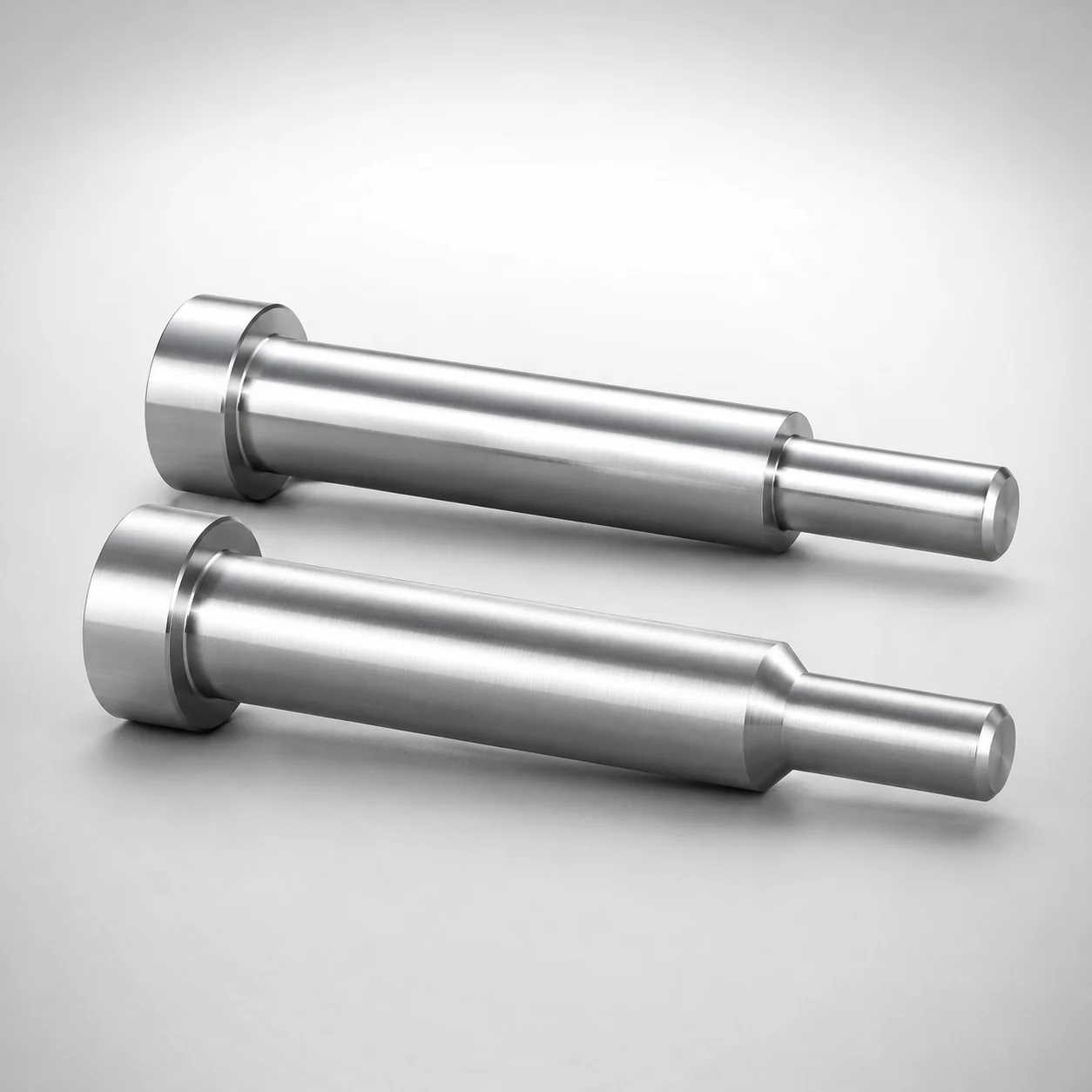
Taperless One-Step Core Pins - No Second Step
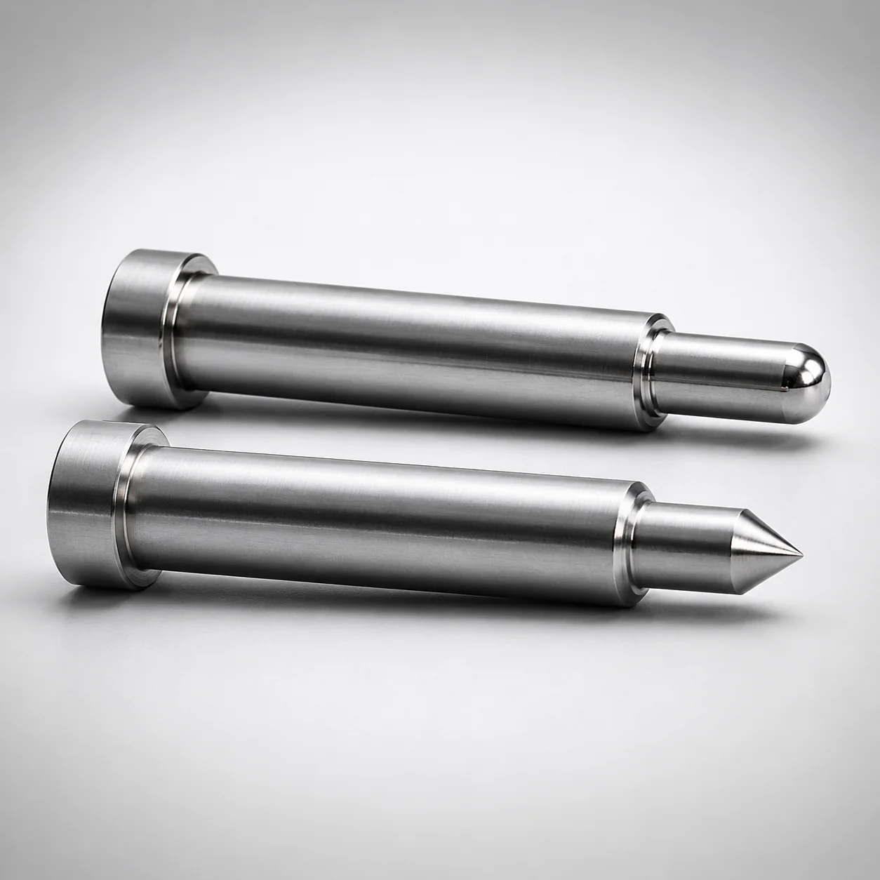
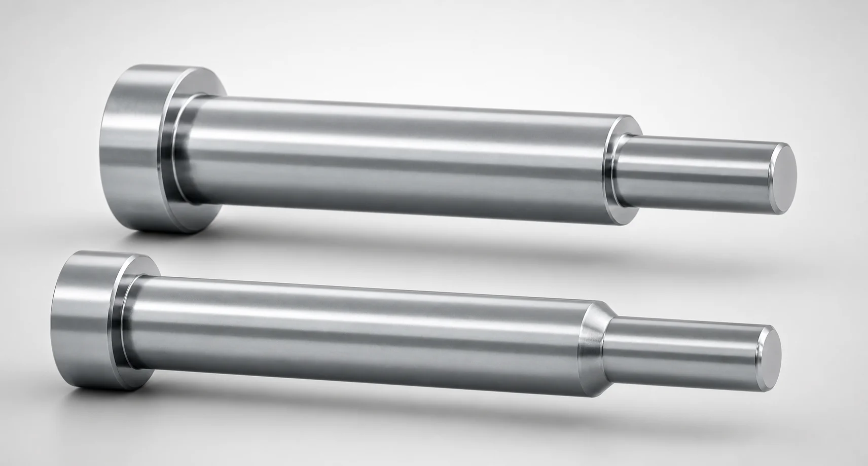
Taperless One-Step Core Pins - No Second Step provide a single-step locating profile for reliable core positioning in progressive and injection molds. The taperless design helps maintain consistent fit during assembly and operation.
- One-step core pin construction with no second step for simplified, stable core location
- SKH51 / SKD61 / NAK80 / SUS440C steel options with quenched & hardened steel performance
- Precision control using Shaft diameter tolerance 0/-0.005 and tip gradient tolerance 0/-0.01
- Built for core pin applications requiring repeatable seating and smooth ejection
Specifications
4248 configurations available
| Material | L Dimension Tolerance | A/AAC (Tip Diameter) (mm) | D/P (Shaft Diameter) (mm) | First Step Shape | Tip Shape | RE (R shape alteration・enlargement) (mm) | C (Step type taper width) (mm) | CVC (C dimension can be designated at 0.01mm increments) (mm) | F (Bearing bore length) (mm) | G (Tip C chamfering width) (mm) | K (Tip angle) (°) | L (L dimension) (mm) | Q (Tip R chamfering) (mm) | R (Step type R) (mm) | S (Tip tapered width) (mm) | type |
|---|---|---|---|---|---|---|---|---|---|---|---|---|---|---|---|---|
| SKH51 | 0/-0.05 | 0.5 ~ 0.99 | 1 | B | B | - | - | - | 10 ~ 99.4 | - | - | 12 ~ 100 | - | - | - | - |
| SKH51 | 0/-0.05 | 0.4 ~ 0.49 | 1 | B | B | - | - | - | 10 ~ 99.4 | - | - | 12 ~ 100 | - | - | - | - |
| SKH51 | 0/-0.05 | 0.5 ~ 1.49 | 1.5 | B | B | - | - | - | 10 ~ 99.4 | - | - | 12 ~ 100 | - | - | - | - |
| SKH51 | 0/-0.05 | 0.4 ~ 0.49 | 1.5 | B | B | - | - | - | 10 ~ 99.4 | - | - | 12 ~ 100 | - | - | - | - |
| SKH51 | 0/-0.05 | 0.5 ~ 1.99 | 2 | B | B | - | - | - | 10 ~ 99.4 | - | - | 12 ~ 100 | - | - | - | - |
| SKH51 | 0/-0.05 | 0.5 ~ 2.49 | 2.5 | B | B | - | - | - | 10 ~ 99.4 | - | - | 12 ~ 100 | - | - | - | - |
| SKH51 | 0/-0.05 | 0.7 ~ 2.99 | 3 | B | B | - | - | - | 10 ~ 99.4 | - | - | 12 ~ 100 | - | - | - | - |
| SKH51 | 0/-0.05 | 1 ~ 3.49 | 3.5 | B | B | - | - | - | 10 ~ 119.4 | - | - | 12 ~ 120 | - | - | - | - |
| SKH51 | 0/-0.05 | 0.7 ~ 0.99 | 3.5 | B | B | - | - | - | 10 ~ 119.4 | - | - | 12 ~ 120 | - | - | - | - |
| SKH51 | 0/-0.05 | 1 ~ 3.99 | 4 | B | B | - | - | - | 10 ~ 119.4 | - | - | 12 ~ 120 | - | - | - | - |
| SKH51 | 0/-0.05 | 0.7 ~ 0.99 | 4 | B | B | - | - | - | 10 ~ 119.4 | - | - | 12 ~ 120 | - | - | - | - |
| SKH51 | 0/-0.05 | 1 ~ 4.49 | 4.5 | B | B | - | - | - | 10 ~ 119.4 | - | - | 12 ~ 120 | - | - | - | - |
| SKH51 | 0/-0.05 | 1 ~ 4.99 | 5 | B | B | - | - | - | 10 ~ 150 | - | - | 12 ~ 150 | - | - | - | - |
| SKH51 | 0/-0.05 | 1.5 ~ 5.49 | 5.5 | B | B | - | - | - | 10 ~ 150 | - | - | 12 ~ 150 | - | - | - | - |
| SKH51 | 0/-0.05 | 1 ~ 1.49 | 5.5 | B | B | - | - | - | 10 ~ 150 | - | - | 12 ~ 150 | - | - | - | - |
| SKH51 | 0/-0.05 | 2 ~ 5.99 | 6 | B | B | - | - | - | 10 ~ 150 | - | - | 12 ~ 150 | - | - | - | - |
| SKH51 | 0/-0.05 | 1.5 ~ 1.99 | 6 | B | B | - | - | - | 10 ~ 150 | - | - | 12 ~ 150 | - | - | - | - |
| SKH51 | 0/-0.05 | 2 ~ 6.49 | 6.5 | B | B | - | - | - | 10 ~ 150 | - | - | 12 ~ 150 | - | - | - | - |
| SKH51 | 0/-0.05 | 1.5 ~ 1.99 | 6.5 | B | B | - | - | - | 10 ~ 150 | - | - | 12 ~ 150 | - | - | - | - |
| SKH51 | 0/-0.05 | 2 ~ 6.99 | 7 | B | B | - | - | - | 10 ~ 150 | - | - | 12 ~ 150 | - | - | - | - |
| SKH51 | 0/-0.05 | 1.5 ~ 1.99 | 7 | B | B | - | - | - | 10 ~ 150 | - | - | 12 ~ 150 | - | - | - | - |
| SKH51 | 0/-0.05 | 2 ~ 7.99 | 8 | B | B | - | - | - | 10 ~ 150 | - | - | 12 ~ 150 | - | - | - | - |
| SKH51 | 0/-0.05 | 1.5 ~ 1.99 | 8 | B | B | - | - | - | 10 ~ 150 | - | - | 12 ~ 150 | - | - | - | - |
| SKH51 | 0/-0.05 | 2 ~ 9.99 | 10 | B | B | - | - | - | 10 ~ 150 | - | - | 12 ~ 150 | - | - | - | - |
| SKH51 | 0/-0.05 | 1.5 ~ 1.99 | 10 | B | B | - | - | - | 10 ~ 150 | - | - | 12 ~ 150 | - | - | - | - |
| SKH51 | 0/-0.05 | 2 ~ 12.99 | 13 | B | B | - | - | - | 10 ~ 150 | - | - | 12 ~ 150 | - | - | - | - |
| SKH51 | 0/-0.05 | 1.5 ~ 1.99 | 13 | B | B | - | - | - | 10 ~ 150 | - | - | 12 ~ 150 | - | - | - | - |
| SKH51 | 0/-0.05 | 2 ~ 15.99 | 16 | B | B | - | - | - | 10 ~ 150 | - | - | 12 ~ 150 | - | - | - | - |
| SKH51 | 0/-0.05 | 1.5 ~ 1.99 | 16 | B | B | - | - | - | 10 ~ 150 | - | - | 12 ~ 150 | - | - | - | - |
| SKH51 | 0/-0.05 | 5 ~ 19.99 | 20 | B | B | - | - | - | 28 ~ 150 | - | - | 30 ~ 150 | - | - | - | - |
| SKH51 | 0/-0.05 | 4 ~ 4.99 | 20 | B | B | - | - | - | 28 ~ 150 | - | - | 30 ~ 150 | - | - | - | - |
| SKH51 | +0.02/0 | 0.5 ~ 0.99 | 1 | B | C | - | - | - | 10 ~ 99.4 | 0.1 ~ 0.4 | - | 12 ~ 100 | - | - | - | - |
| SKH51 | +0.02/0 | 0.4 ~ 0.49 | 1 | B | C | - | - | - | 10 ~ 99.4 | 0.1 ~ 0.4 | - | 12 ~ 100 | - | - | - | - |
| SKH51 | +0.02/0 | 0.5 ~ 1.49 | 1.5 | B | C | - | - | - | 10 ~ 99.4 | 0.1 ~ 0.7 | - | 12 ~ 100 | - | - | - | - |
| SKH51 | +0.02/0 | 0.4 ~ 0.49 | 1.5 | B | C | - | - | - | 10 ~ 99.4 | 0.1 ~ 0.7 | - | 12 ~ 100 | - | - | - | - |
| SKH51 | +0.02/0 | 0.5 ~ 1.99 | 2 | B | C | - | - | - | 10 ~ 99.4 | 0.1 ~ 0.9 | - | 12 ~ 100 | - | - | - | - |
| SKH51 | +0.02/0 | 0.5 ~ 2.49 | 2.5 | B | C | - | - | - | 10 ~ 99.4 | 0.1 ~ 1.2 | - | 12 ~ 100 | - | - | - | - |
| SKH51 | +0.02/0 | 0.7 ~ 2.99 | 3 | B | C | - | - | - | 10 ~ 99.4 | 0.1 ~ 1.4 | - | 12 ~ 100 | - | - | - | - |
| SKH51 | +0.02/0 | 1 ~ 3.49 | 3.5 | B | C | - | - | - | 10 ~ 119.4 | 0.1 ~ 1.7 | - | 12 ~ 120 | - | - | - | - |
| SKH51 | +0.02/0 | 0.7 ~ 0.99 | 3.5 | B | C | - | - | - | 10 ~ 119.4 | 0.1 ~ 1.7 | - | 12 ~ 120 | - | - | - | - |
| SKH51 | +0.02/0 | 1 ~ 3.99 | 4 | B | C | - | - | - | 10 ~ 119.4 | 0.1 ~ 1.9 | - | 12 ~ 120 | - | - | - | - |
| SKH51 | +0.02/0 | 0.7 ~ 0.99 | 4 | B | C | - | - | - | 10 ~ 119.4 | 0.1 ~ 1.9 | - | 12 ~ 120 | - | - | - | - |
| SKH51 | +0.02/0 | 1 ~ 4.49 | 4.5 | B | C | - | - | - | 10 ~ 119.4 | 0.1 ~ 2.2 | - | 12 ~ 120 | - | - | - | - |
| SKH51 | +0.02/0 | 1 ~ 4.99 | 5 | B | C | - | - | - | 10 ~ 150 | 0.1 ~ 2.4 | - | 12 ~ 150 | - | - | - | - |
| SKH51 | +0.02/0 | 1.5 ~ 5.49 | 5.5 | B | C | - | - | - | 10 ~ 150 | 0.1 ~ 2.7 | - | 12 ~ 150 | - | - | - | - |
| SKH51 | +0.02/0 | 1 ~ 1.49 | 5.5 | B | C | - | - | - | 10 ~ 150 | 0.1 ~ 2.7 | - | 12 ~ 150 | - | - | - | - |
| SKH51 | +0.02/0 | 2 ~ 5.99 | 6 | B | C | - | - | - | 10 ~ 150 | 0.1 ~ 2.9 | - | 12 ~ 150 | - | - | - | - |
| SKH51 | +0.02/0 | 1.5 ~ 1.99 | 6 | B | C | - | - | - | 10 ~ 150 | 0.1 ~ 2.9 | - | 12 ~ 150 | - | - | - | - |
| SKH51 | +0.02/0 | 2 ~ 6.49 | 6.5 | B | C | - | - | - | 10 ~ 150 | 0.1 ~ 3.2 | - | 12 ~ 150 | - | - | - | - |
| SKH51 | +0.02/0 | 1.5 ~ 1.99 | 6.5 | B | C | - | - | - | 10 ~ 150 | 0.1 ~ 3.2 | - | 12 ~ 150 | - | - | - | - |
Product Guide
Application Scenarios+
Taperless one-step core pins are used in injection mold assemblies where the core must be seated repeatably without a second locating step. In automotive connector housings, the one-piece locating profile supports stable core position during clamp-to-clamp cycles, reducing the risk of gradual misalignment that can cause flash or inconsistent cavity fill.
In medical device component molds (e.g., small housings and housings with fine features), the taperless geometry helps maintain consistent fit during assembly and improves repeatability of ejection behavior. The variant’s no-second-step design is especially suited when designers want a single, controlled seating surface rather than a staged alignment.
For electronics housings and progressive-injection hybrids, these core pins support reliable alignment under frequent tool operation. Select this specific variant to take advantage of the provided shaft/tip tolerance control for smooth, stable core positioning.
Material & Process Details+
This series is available in SKH51, SKD61, NAK80, or SUS440C, allowing material selection based on wear resistance, toughness, and thermal performance needs. Shaft and tip features are manufactured for precision location, then supplied in a heat-treated condition suitable for core pin service.
- SKH51 (tool steel equivalent to AISI M2): high wear resistance; typically a better choice when surface durability under sliding/impact is critical, with a trade-off of reduced toughness versus more ductile grades.
- SKD61 (≈ AISI H13): excellent balance of hot-work durability and toughness, commonly used where repeated thermal cycling is expected.
- NAK80: good for fine surface replication and dimensional stability for precision cores.
- SUS440C: corrosion-resistant option with good hardness and wear performance for environments where corrosion control matters.
Hardness levels and specific heat-treatment state (e.g., quenched & tempered) are stated in the product description as quenched & hardened for these steel options.
Sizing & Selection Guide+
Use the provided dimensional ranges to match the core pin to your mold core/cavity locating requirements. For shaft sizing, select D/P = 1 to 20 mm; choose A/AAC (tip diameter) = 0.4 to 5 mm to control tip seating engagement.
The one-step feature is dimensioned by L = 12 to 30 mm (overall L dimension) and the bearing bore length F = 10 to 28 mm. Tip geometry is selected via the specified tip shapes (B, C, G, R, S, T) and tip angle K = 21 to 60° (or 1 to 45° depending on the configuration). For step/travel control, ensure the fixed RE = 0.5 to 2 mm, C (taper width) = 0.1 to 4 mm, and CVC setting (0.1 to 1 mm at 0.01 mm increments) align with your mating pocket geometry.
- Tolerance matching: shaft diameter tolerance is 0/-0.005 mm and tip gradient tolerance is 0/-0.01 mm, so verify pocket/groove clearance to prevent interference on assembly.
- Fit considerations: since dimensions are controlled one-sided (negative), plan for the smallest delivered diameter when sizing retaining clearances.
Frequently Asked Questions
What shaft diameter tolerance (D/P) and tip gradient tolerance does this one-step core pin series provide?+
The shaft diameter tolerance is 0/-0.005 mm (D/P sized up to 1–20 mm). The tip gradient tolerance is 0/-0.01 mm, which helps maintain consistent one-step seating behavior when assembling and cycling the core.
How do I choose between SKH51, SKD61, NAK80, and SUS440C for taperless core pins?+
Use SKH51 when high wear resistance is needed (noting the toughness trade-off typical of M2-class steels). Choose SKD61 for a balanced option under repeated thermal cycling (H13-class performance), while NAK80 supports precision applications requiring dimensional stability. Select SUS440C when corrosion resistance is important alongside hardness and wear performance.
What are the usable ranges for tip diameter (A/AAC) and overall L dimension when selecting this core pin?+
The tip diameter range is A/AAC = 0.4 to 5 mm. The overall L dimension range is 12 to 30 mm, and you can pair it with the bearing bore length F = 10 to 28 mm to fit the core locating depth in your tool.
Can I configure the C dimension at 0.01 mm increments, and what limits apply for CVC?+
Yes. The CVC value (C dimension can be designated at 0.01 mm increments) is available in the range 0.1 to 1 mm. This is used to fine-tune how the one-step taper/travel engages with the mating pocket geometry.
Which fixed dimensions must be checked to ensure correct one-step locating without interference?+
When integrating the pin into the mold, verify the fixed profile parameters including RE = 0.5 to 2 mm and C (step type taper width) = 0.1 to 4 mm. Also confirm the tolerance-sensitive sections (shaft 0/-0.005 mm and tip gradient 0/-0.01 mm) and account for negative-only dimensional delivery when setting clearances.
Related Products
Need Custom Specifications?
Our engineering team can help with custom configurations, material selection, and volume pricing.