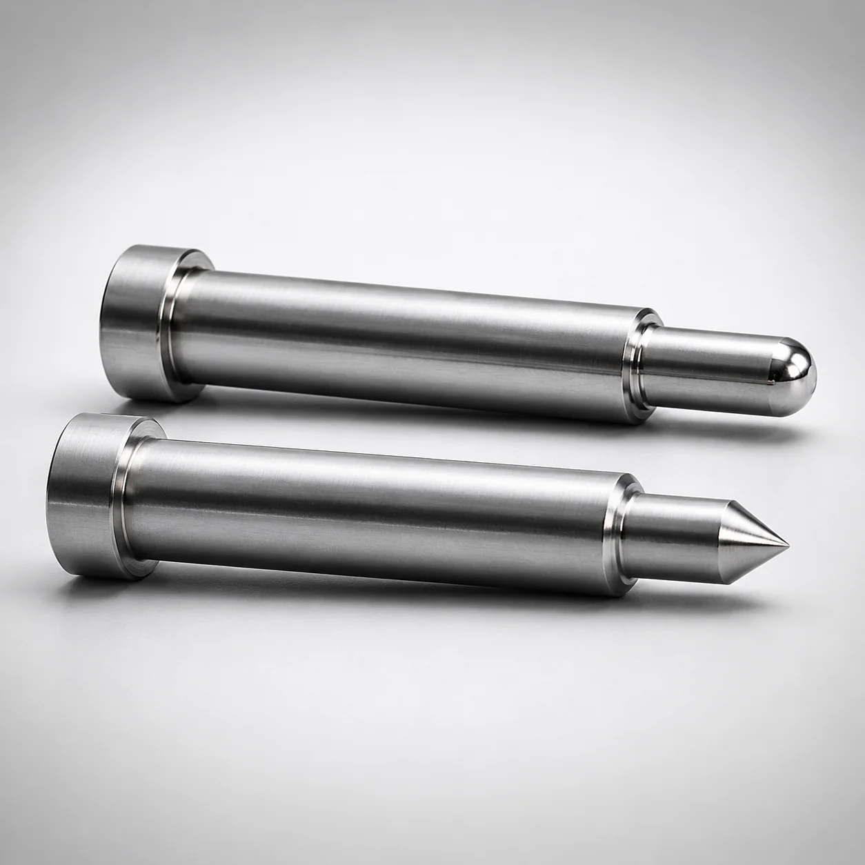
Precision Taperless One-Step Core Pins - Configurable Shaft Diameter
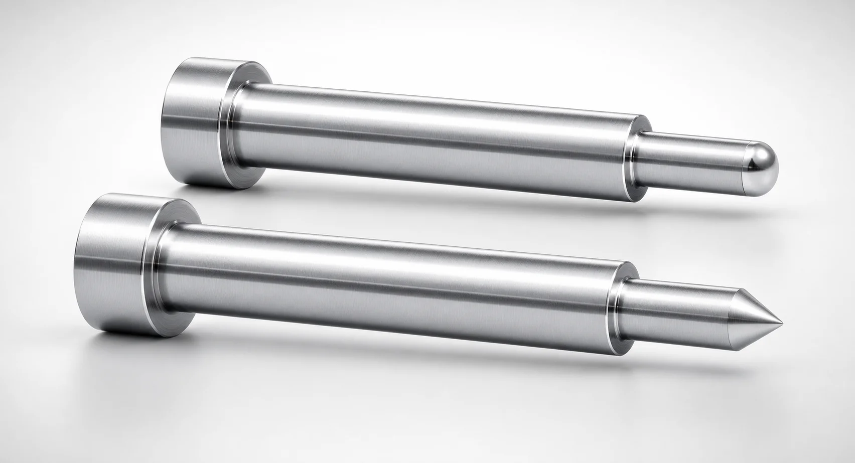
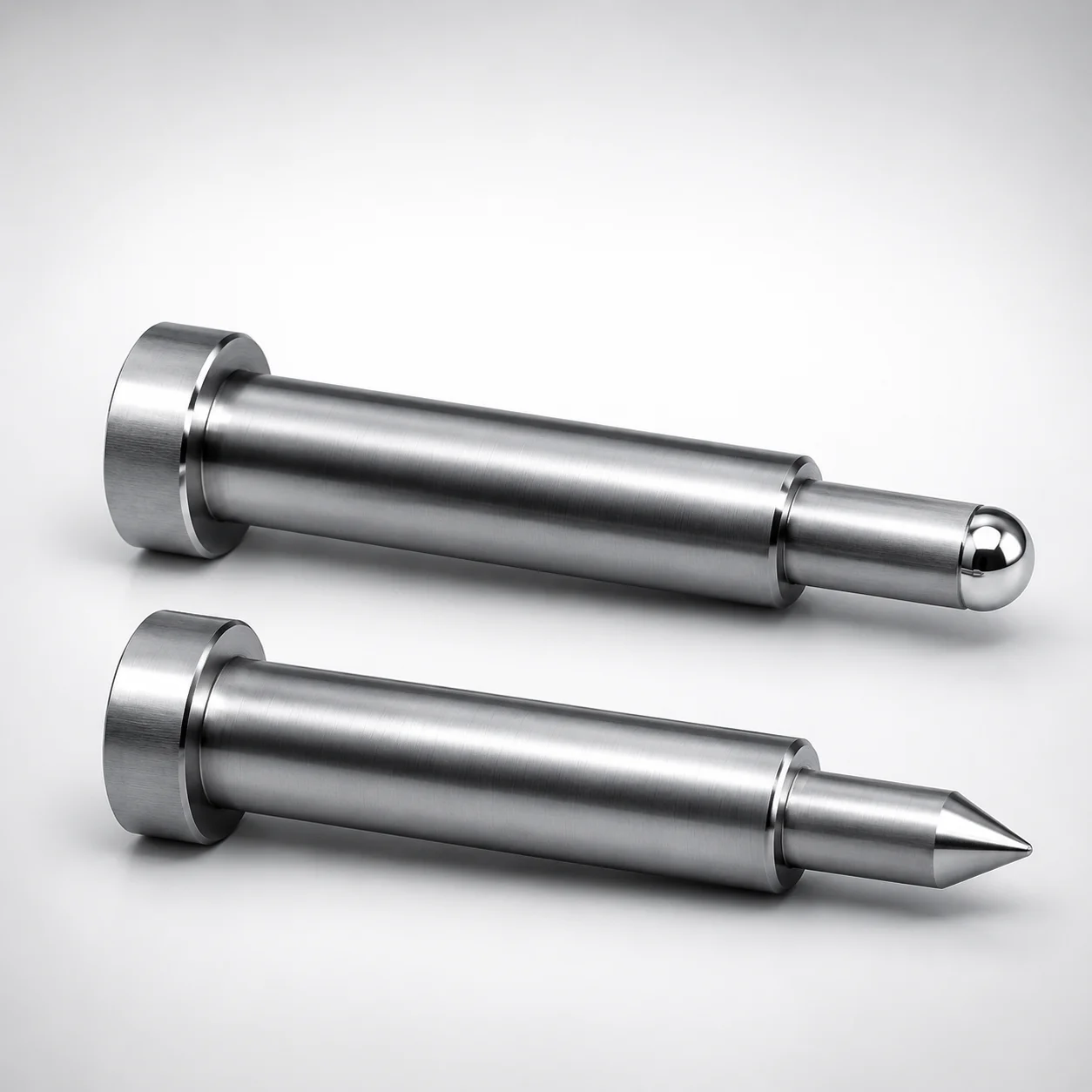
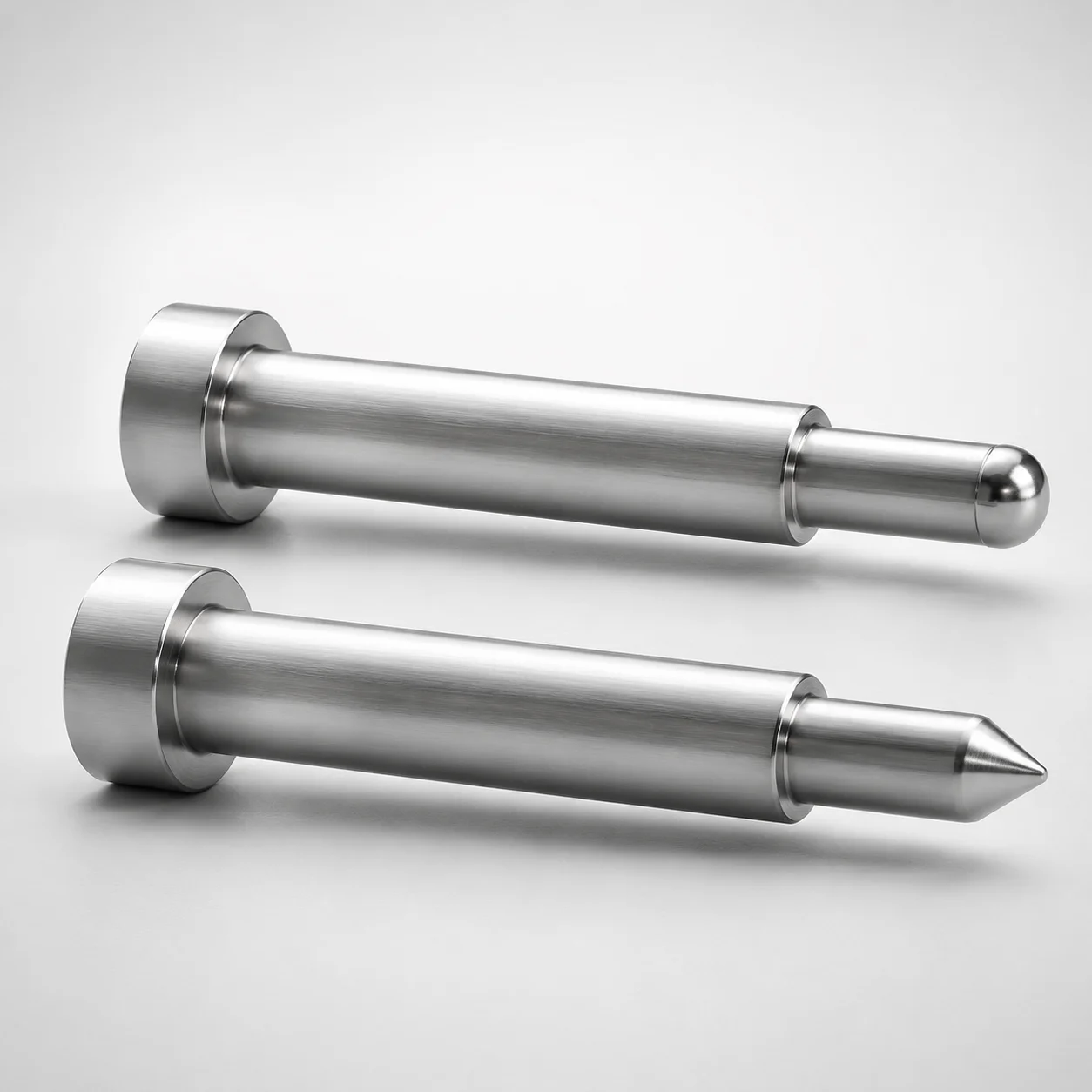
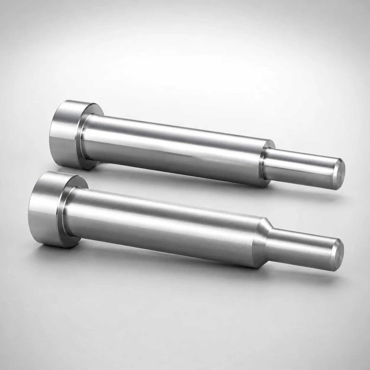
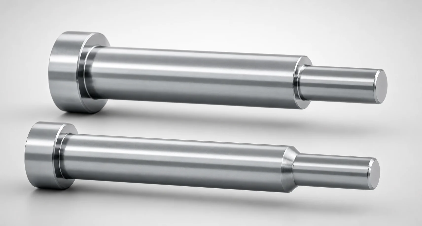
Precision taperless one-step core pins (configurable shaft diameter) are designed for accurate mold core locating using a compact one-step geometry. The taperless profile helps maintain consistent alignment during assembly and operation.
- One-step construction with no second step for predictable locating behavior
- Controlled tip geometry supports stable core alignment and repeatable fits
- Tight shaft and tip gradient tolerances for precise press-to-core positioning
- Built for toolmaking workflows using SKH51 or SKD61 hardened steel options
Specifications
4324 configurations available
| Material | L Dimension Tolerance | A/AAC (Tip Diameter) (mm) | D/P (Shaft Diameter) (mm) | First Step Shape | Tip Shape | No. (Nominal diameter) (mm) | C (Step type taper width) (mm) | CVC (C dimension can be designated at 0.01mm increments) (mm) | F (Bearing bore length) (mm) | FC (Makes F dimension shorter than F min) (mm) | G (Tip C chamfering width) (mm) | K (Tip angle) (°) | L (L dimension) (mm) | Q (Tip R chamfering) (mm) | R (Step type R) (mm) | S (Tip tapered width) (mm) | type |
|---|---|---|---|---|---|---|---|---|---|---|---|---|---|---|---|---|---|
| SKH51 | 0/-0.05 | 0.5 ~ 0.98 | 0.8 ~ 0.995 | B | B | 1 | - | - | 12 ~ 99.3 | - | - | - | 6.5 ~ 100 | - | - | - | - |
| SKH51 | 0/-0.05 | 0.4 ~ 0.49 | 0.8 ~ 0.995 | B | B | 1 | - | - | 12 ~ 99.3 | - | - | - | 6.5 ~ 100 | - | - | - | - |
| SKH51 | 0/-0.05 | 0.5 ~ 0.98 | 0.8 ~ 0.995 | B | B | 1 | - | - | - | 5 ~ 13.44 | - | - | 6.5 ~ 100 | - | - | - | - |
| SKH51 | 0/-0.05 | 0.4 ~ 0.49 | 0.8 ~ 0.995 | B | B | 1 | - | - | - | 5 ~ 13.44 | - | - | 6.5 ~ 100 | - | - | - | - |
| SKH51 | 0/-0.05 | 0.5 ~ 1.48 | 1 ~ 1.495 | B | B | 1.5 | - | - | 12 ~ 99.3 | - | - | - | 6.5 ~ 100 | - | - | - | - |
| SKH51 | 0/-0.05 | 0.4 ~ 0.49 | 1 ~ 1.495 | B | B | 1.5 | - | - | 12 ~ 99.3 | - | - | - | 6.5 ~ 100 | - | - | - | - |
| SKH51 | 0/-0.05 | 0.5 ~ 1.48 | 1 ~ 1.495 | B | B | 1.5 | - | - | - | 5 ~ 13.44 | - | - | 6.5 ~ 100 | - | - | - | - |
| SKH51 | 0/-0.05 | 0.4 ~ 0.49 | 1 ~ 1.495 | B | B | 1.5 | - | - | - | 5 ~ 13.44 | - | - | 6.5 ~ 100 | - | - | - | - |
| SKH51 | 0/-0.05 | 0.5 ~ 1.98 | 1.5 ~ 1.995 | B | B | 2 | - | - | 12 ~ 99.3 | - | - | - | 6.5 ~ 100 | - | - | - | - |
| SKH51 | 0/-0.05 | 0.5 ~ 0.69 | 1.5 ~ 1.995 | B | B | 2 | - | - | 12 ~ 99.3 | - | - | - | 6.5 ~ 100 | - | - | - | - |
| SKH51 | 0/-0.05 | 0.5 ~ 1.98 | 1.5 ~ 1.995 | B | B | 2 | - | - | - | 5 ~ 13.44 | - | - | 6.5 ~ 100 | - | - | - | - |
| SKH51 | 0/-0.05 | 0.5 ~ 0.69 | 1.5 ~ 1.995 | B | B | 2 | - | - | - | 5 ~ 13.44 | - | - | 6.5 ~ 100 | - | - | - | - |
| SKH51 | 0/-0.05 | 0.5 ~ 2.48 | 2 ~ 2.495 | B | B | 2.5 | - | - | 12 ~ 99.3 | - | - | - | 6.5 ~ 100 | - | - | - | - |
| SKH51 | 0/-0.05 | 0.5 ~ 0.69 | 2 ~ 2.495 | B | B | 2.5 | - | - | 12 ~ 99.3 | - | - | - | 6.5 ~ 100 | - | - | - | - |
| SKH51 | 0/-0.05 | 0.5 ~ 2.48 | 2 ~ 2.495 | B | B | 2.5 | - | - | - | 5 ~ 13.44 | - | - | 6.5 ~ 100 | - | - | - | - |
| SKH51 | 0/-0.05 | 0.5 ~ 0.69 | 2 ~ 2.495 | B | B | 2.5 | - | - | - | 5 ~ 13.44 | - | - | 6.5 ~ 100 | - | - | - | - |
| SKH51 | 0/-0.05 | 0.7 ~ 2.98 | 2.5 ~ 2.995 | B | B | 3 | - | - | 12 ~ 99.3 | - | - | - | 6.5 ~ 100 | - | - | - | - |
| SKH51 | 0/-0.05 | 0.7 ~ 0.99 | 2.5 ~ 2.995 | B | B | 3 | - | - | 12 ~ 99.3 | - | - | - | 6.5 ~ 100 | - | - | - | - |
| SKH51 | 0/-0.05 | 0.7 ~ 2.98 | 2.5 ~ 2.995 | B | B | 3 | - | - | - | 5 ~ 13.44 | - | - | 6.5 ~ 100 | - | - | - | - |
| SKH51 | 0/-0.05 | 0.7 ~ 0.99 | 2.5 ~ 2.995 | B | B | 3 | - | - | - | 5 ~ 13.44 | - | - | 6.5 ~ 100 | - | - | - | - |
| SKH51 | 0/-0.05 | 1 ~ 3.48 | 3 ~ 3.495 | B | B | 3.5 | - | - | 12 ~ 119.3 | - | - | - | 6.5 ~ 120 | - | - | - | - |
| SKH51 | 0/-0.05 | 0.7 ~ 0.99 | 3 ~ 3.495 | B | B | 3.5 | - | - | 12 ~ 119.3 | - | - | - | 6.5 ~ 120 | - | - | - | - |
| SKH51 | 0/-0.05 | 1 ~ 3.48 | 3 ~ 3.495 | B | B | 3.5 | - | - | - | 5 ~ 13.44 | - | - | 6.5 ~ 120 | - | - | - | - |
| SKH51 | 0/-0.05 | 0.7 ~ 0.99 | 3 ~ 3.495 | B | B | 3.5 | - | - | - | 5 ~ 13.44 | - | - | 6.5 ~ 120 | - | - | - | - |
| SKH51 | 0/-0.05 | 1 ~ 3.98 | 3.5 ~ 3.995 | B | B | 4 | - | - | 12 ~ 119.3 | - | - | - | 6.5 ~ 120 | - | - | - | - |
| SKH51 | 0/-0.05 | 0.7 ~ 0.99 | 3.5 ~ 3.995 | B | B | 4 | - | - | 12 ~ 119.3 | - | - | - | 6.5 ~ 120 | - | - | - | - |
| SKH51 | 0/-0.05 | 1 ~ 3.98 | 3.5 ~ 3.995 | B | B | 4 | - | - | - | 5 ~ 13.44 | - | - | 6.5 ~ 120 | - | - | - | - |
| SKH51 | 0/-0.05 | 0.7 ~ 0.99 | 3.5 ~ 3.995 | B | B | 4 | - | - | - | 5 ~ 13.44 | - | - | 6.5 ~ 120 | - | - | - | - |
| SKH51 | 0/-0.05 | 1 ~ 4.48 | 4 ~ 4.495 | B | B | 4.5 | - | - | 12 ~ 119.3 | - | - | - | 6.5 ~ 120 | - | - | - | - |
| SKH51 | 0/-0.05 | 1 ~ 1.49 | 4 ~ 4.495 | B | B | 4.5 | - | - | 12 ~ 119.3 | - | - | - | 6.5 ~ 120 | - | - | - | - |
| SKH51 | 0/-0.05 | 1 ~ 4.48 | 4 ~ 4.495 | B | B | 4.5 | - | - | - | 5 ~ 13.44 | - | - | 6.5 ~ 120 | - | - | - | - |
| SKH51 | 0/-0.05 | 1 ~ 1.49 | 4 ~ 4.495 | B | B | 4.5 | - | - | - | 5 ~ 13.44 | - | - | 6.5 ~ 120 | - | - | - | - |
| SKH51 | 0/-0.05 | 1 ~ 4.98 | 4.5 ~ 4.995 | B | B | 5 | - | - | 12 ~ 150 | - | - | - | 6.5 ~ 150 | - | - | - | - |
| SKH51 | 0/-0.05 | 1 ~ 1.49 | 4.5 ~ 4.995 | B | B | 5 | - | - | 12 ~ 150 | - | - | - | 6.5 ~ 150 | - | - | - | - |
| SKH51 | 0/-0.05 | 1 ~ 4.98 | 4.5 ~ 4.995 | B | B | 5 | - | - | - | 5 ~ 13.44 | - | - | 6.5 ~ 150 | - | - | - | - |
| SKH51 | 0/-0.05 | 1 ~ 1.49 | 4.5 ~ 4.995 | B | B | 5 | - | - | - | 5 ~ 13.44 | - | - | 6.5 ~ 150 | - | - | - | - |
| SKH51 | 0/-0.05 | 1.5 ~ 5.48 | 5 ~ 5.495 | B | B | 5.5 | - | - | 12 ~ 150 | - | - | - | 6.5 ~ 150 | - | - | - | - |
| SKH51 | 0/-0.05 | 1 ~ 1.49 | 5 ~ 5.495 | B | B | 5.5 | - | - | 12 ~ 150 | - | - | - | 6.5 ~ 150 | - | - | - | - |
| SKH51 | 0/-0.05 | 1.5 ~ 5.48 | 5 ~ 5.495 | B | B | 5.5 | - | - | - | 5 ~ 13.44 | - | - | 6.5 ~ 150 | - | - | - | - |
| SKH51 | 0/-0.05 | 1 ~ 1.49 | 5 ~ 5.495 | B | B | 5.5 | - | - | - | 5 ~ 13.44 | - | - | 6.5 ~ 150 | - | - | - | - |
| SKH51 | 0/-0.05 | 2 ~ 5.98 | 5.5 ~ 5.995 | B | B | 6 | - | - | 12 ~ 150 | - | - | - | 6.5 ~ 150 | - | - | - | - |
| SKH51 | 0/-0.05 | 1.5 ~ 1.99 | 5.5 ~ 5.995 | B | B | 6 | - | - | 12 ~ 150 | - | - | - | 6.5 ~ 150 | - | - | - | - |
| SKH51 | 0/-0.05 | 2 ~ 5.98 | 5.5 ~ 5.995 | B | B | 6 | - | - | - | 5 ~ 13.44 | - | - | 6.5 ~ 150 | - | - | - | - |
| SKH51 | 0/-0.05 | 1.5 ~ 1.99 | 5.5 ~ 5.995 | B | B | 6 | - | - | - | 5 ~ 13.44 | - | - | 6.5 ~ 150 | - | - | - | - |
| SKH51 | 0/-0.05 | 2 ~ 6.48 | 6 ~ 6.495 | B | B | 6.5 | - | - | 12 ~ 150 | - | - | - | 6.5 ~ 150 | - | - | - | - |
| SKH51 | 0/-0.05 | 1.5 ~ 1.99 | 6 ~ 6.495 | B | B | 6.5 | - | - | 12 ~ 150 | - | - | - | 6.5 ~ 150 | - | - | - | - |
| SKH51 | 0/-0.05 | 2 ~ 6.48 | 6 ~ 6.495 | B | B | 6.5 | - | - | - | 5 ~ 13.44 | - | - | 6.5 ~ 150 | - | - | - | - |
| SKH51 | 0/-0.05 | 1.5 ~ 1.99 | 6 ~ 6.495 | B | B | 6.5 | - | - | - | 5 ~ 13.44 | - | - | 6.5 ~ 150 | - | - | - | - |
| SKH51 | 0/-0.05 | 2 ~ 6.98 | 6.5 ~ 6.995 | B | B | 7 | - | - | 12 ~ 150 | - | - | - | 6.5 ~ 150 | - | - | - | - |
| SKH51 | 0/-0.05 | 1.5 ~ 1.99 | 6.5 ~ 6.995 | B | B | 7 | - | - | 12 ~ 150 | - | - | - | 6.5 ~ 150 | - | - | - | - |
Product Guide
Application Scenarios+
These precision taperless one-step core pins are used for mold core locating in injection molding toolsets where repeatable positioning is critical. The compact one-step geometry provides predictable engagement without relying on a second step, helping maintain stable alignment through assembly and operating cycles.
- Automotive connector and housing molds: Use the configurable shaft diameter range D/P = 0.8–16 mm to match specific core bore layouts, supporting tight press-to-core positioning and consistent part-to-cavity alignment.
- Medical device component tooling: The controlled tip diameter options A/AAC = 0.4–5 mm and stable locating behavior help reduce positional variation that can affect thin-wall features and assembly fit.
- General consumer and electrical enclosure molds: The shorter, one-step contact design is suited when space constraints limit multi-step locating features while still requiring reliable core centering.
Hardened steel variants (SKH51 or SKD61) support tool life under normal wear and repeated press-fit cycling.
Material & Process Details+
Material options are SKH51 and SKD61 hardened steels, selected to balance wear resistance and toughness for repeated locating contact. In practice, SKH51 is commonly chosen for higher wear resistance applications, while SKD61 is widely used where a stronger toughness-to-hardness balance is required for tool durability.
- SKH51: Typically treated as a high-speed steel grade (often referenced as an AISI M2–class equivalent) and supplied in a hardened state for good resistance to abrasion at the pin tip.
- SKD61: Commonly referenced as an H13-class equivalent, suitable for quenched-and-tempered performance where shock resistance during molding cycles is important.
Hardness is not specified in the provided data, so select the exact heat-treatment level offered by your supplier configuration to meet your wear vs. toughness requirements. For best results, verify hardness at the contact region (tip/step) because it strongly affects galling, rounding, and long-run positional repeatability.
Sizing & Selection Guide+
Select dimensions by matching the locating interface between the pin tip/step and the corresponding core bore or locating pocket in the tool. This series is designed for configurable shaft diameter, so start with the required shaft size and then confirm the tip geometry that performs the actual locating.
- Shaft diameter (D/P): Choose within 0.8–16 mm to fit the core bore without over-sizing. Confirm any bearing or guidance length requirements using F = 12–28 mm (and variant-dependent FC when F must be shortened).
- Tip diameter (A/AAC): Select from 0.4–5 mm to achieve stable core centering at the intended engagement depth.
- Length (L): Use the available ranges such as 6.5–100 mm, 6.5–120 mm, or up to 6.5–150 mm depending on the configuration; verify the L tolerance = 0/-0.05 mm, +0.01/0 for stack-up control.
Because the tip and step shapes are selectable (e.g., first step shape B/C/D/E; tip shapes B/C/G/R/S/T; step type taper width C ranges), ensure the chosen step/angle (e.g., K = 21–60° or 1–45° configurations) matches the mating pocket form for repeatable press fit and alignment.
Frequently Asked Questions
How do I choose the correct shaft diameter (D/P) for stable core locating?+
Use the provided D/P (shaft diameter) range of 0.8–16 mm to match the core locating bore size in your mold design. Confirm that the guidance length requirement is met by selecting an appropriate F (bearing bore length) of 12–28 mm or a shortened configuration via FC when needed. Finally, validate the length stack using the L tolerance (0/-0.05, +0.01/0) to maintain repeatable engagement.
What tip diameter range (A/AAC) should I use to control alignment at the core interface?+
Select the locating tip diameter from A/AAC = 0.4–5 mm. This directly affects the stabilizing contact at the one-step geometry interface, which is intended to maintain alignment during tool assembly and molding cycles. Pair the chosen tip size with a compatible tip shape (B/C/G/R/S/T) and matching step geometry to ensure predictable press-to-core positioning.
What does “taperless one-step” mean for fit consistency, and how does it differ from two-step designs?+
This series uses a compact one-step geometry with no second step, which reduces variability in how the pin locates after press-fit. By relying on a single primary engagement zone, the locating behavior is intended to be more predictable across assemblies. This helps minimize positional drift caused by differential contact at multiple step heights.
Which material should I select—SKH51 or SKD61—for locating pins under repeated wear?+
The product supports SKH51 and SKD61 steel variants. SKH51 is typically used when higher wear resistance is preferred (often referenced as an AISI M2–class equivalent), while SKD61 is commonly selected for a strong toughness-to-hardness balance (often referenced as an H13-class equivalent). Choose based on your mold cycle severity and whether wear at the tip or toughness during thermal/press cycles is the dominant risk.
How do I select length (L) and ensure it will meet the tolerance requirements for tool stack-up?+
Pick L within the available configuration ranges (for example 6.5–100, 6.5–120, or 6.5–150 mm). Use the specified L dimension tolerance of 0/-0.05 mm, +0.01/0 to check how the pin length will contribute to your tool stack-up. This is particularly important when multiple components share the same reference planes for core-to-cavity alignment.
Related Products
Need Custom Specifications?
Our engineering team can help with custom configurations, material selection, and volume pricing.