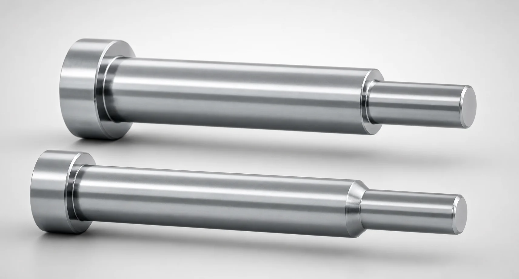
Taperless One-Step Core Pins
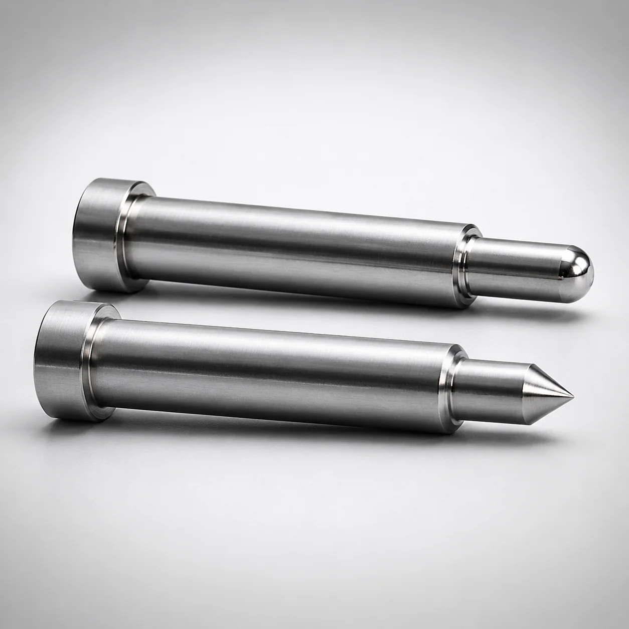
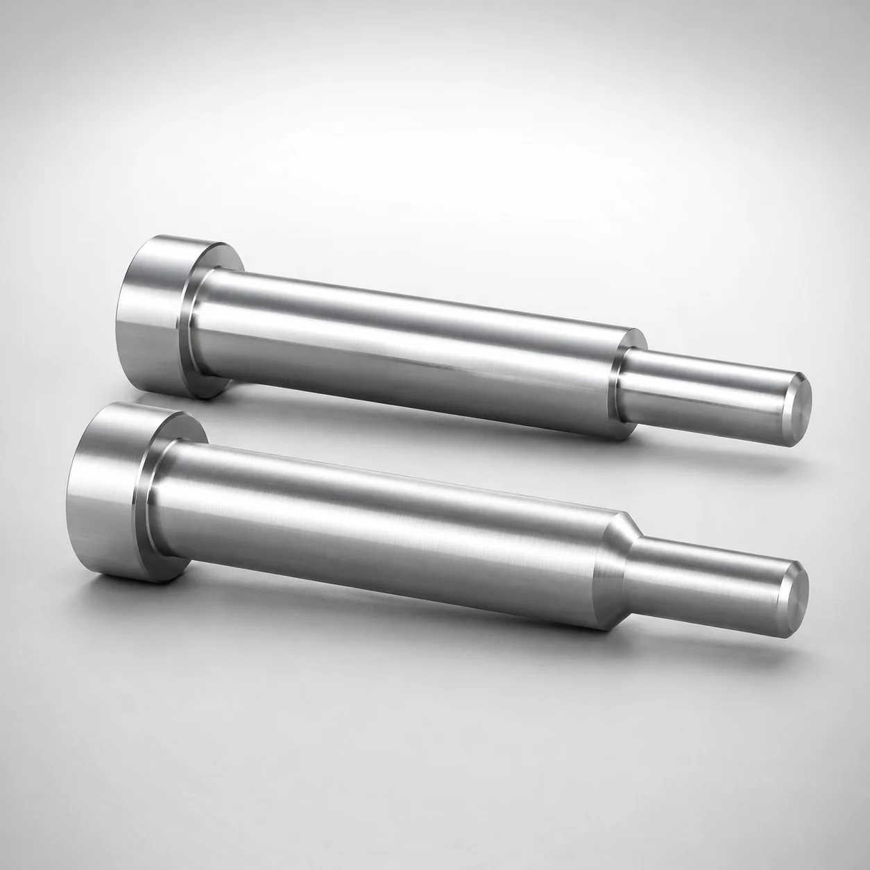
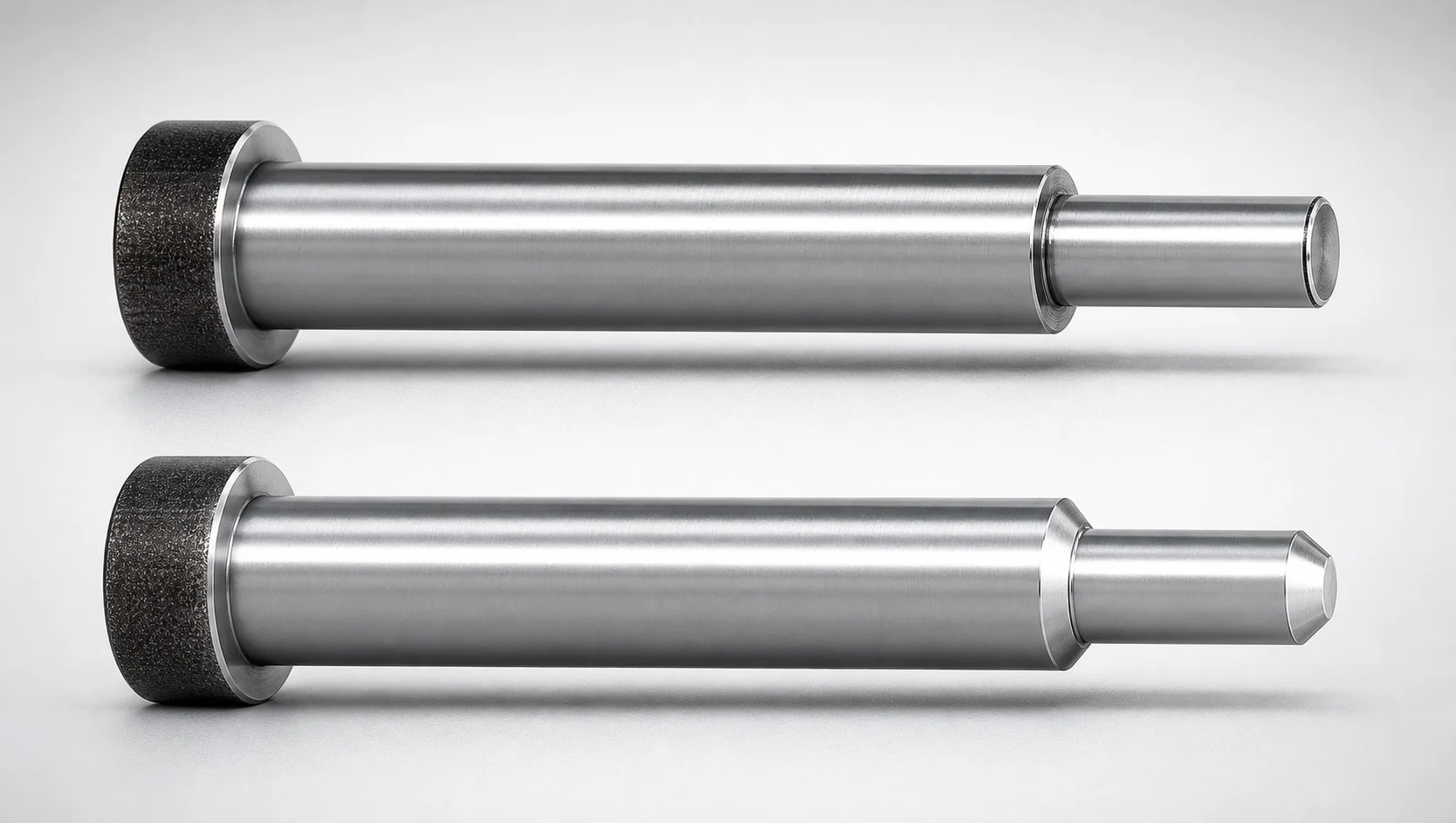
Taperless one-step core pins (configurable shaft diameter) are engineered for precise mold component placement using a one-step profile with no second step. The taperless geometry supports repeatable alignment during assembly and production.
- One-step core pin form with no second step for consistent seating and alignment
- Options of SKH51, SKD61, NAK80, or SUS440C for tailored wear and corrosion needs
- Supports tight machining performance with configurable shaft diameter tolerances (e.g., 0/-0.005)
- Ideal for precision injection molds and die sets requiring reliable core positioning
Specifications
4247 configurations available
| Material | L Dimension Tolerance | A/AAC (Tip Diameter) (mm) | D/P (Shaft Diameter) (mm) | First Step Shape | Tip Shape | No. (Nominal diameter) (mm) | RE (R shape alteration・enlargement) (mm) | C (Step type taper width) (mm) | CVC (C dimension can be designated at 0.01mm increments) (mm) | F (Bearing bore length) (mm) | G (Tip C chamfering width) (mm) | K (Tip angle) (°) | L (L dimension) (mm) | Q (Tip R chamfering) (mm) | R (Step type R) (mm) | S (Tip tapered width) (mm) | type |
|---|---|---|---|---|---|---|---|---|---|---|---|---|---|---|---|---|---|
| SKH51 | 0/-0.05 | 0.5 ~ 0.98 | 0.8 ~ 0.99 | B | B | 1 | - | - | - | 10 ~ 99.3 | - | - | 12 ~ 100 | - | - | - | - |
| SKH51 | 0/-0.05 | 0.4 ~ 0.49 | 0.8 ~ 0.99 | B | B | 1 | - | - | - | 10 ~ 99.3 | - | - | 12 ~ 100 | - | - | - | - |
| SKH51 | 0/-0.05 | 0.5 ~ 1.48 | 1 ~ 1.49 | B | B | 1.5 | - | - | - | 10 ~ 99.3 | - | - | 12 ~ 100 | - | - | - | - |
| SKH51 | 0/-0.05 | 0.4 ~ 0.49 | 1 ~ 1.49 | B | B | 1.5 | - | - | - | 10 ~ 99.3 | - | - | 12 ~ 100 | - | - | - | - |
| SKH51 | 0/-0.05 | 0.5 ~ 1.98 | 1.5 ~ 1.99 | B | B | 2 | - | - | - | 10 ~ 99.3 | - | - | 12 ~ 100 | - | - | - | - |
| SKH51 | 0/-0.05 | 0.5 ~ 2.48 | 2 ~ 2.49 | B | B | 2.5 | - | - | - | 10 ~ 99.3 | - | - | 12 ~ 100 | - | - | - | - |
| SKH51 | 0/-0.05 | 0.7 ~ 2.98 | 2.5 ~ 2.99 | B | B | 3 | - | - | - | 10 ~ 99.3 | - | - | 12 ~ 100 | - | - | - | - |
| SKH51 | 0/-0.05 | 1 ~ 3.48 | 3 ~ 3.49 | B | B | 3.5 | - | - | - | 10 ~ 119.3 | - | - | 12 ~ 120 | - | - | - | - |
| SKH51 | 0/-0.05 | 0.7 ~ 0.99 | 3 ~ 3.49 | B | B | 3.5 | - | - | - | 10 ~ 119.3 | - | - | 12 ~ 120 | - | - | - | - |
| SKH51 | 0/-0.05 | 1 ~ 3.98 | 3.5 ~ 3.99 | B | B | 4 | - | - | - | 10 ~ 119.3 | - | - | 12 ~ 120 | - | - | - | - |
| SKH51 | 0/-0.05 | 0.7 ~ 0.99 | 3.5 ~ 3.99 | B | B | 4 | - | - | - | 10 ~ 119.3 | - | - | 12 ~ 120 | - | - | - | - |
| SKH51 | 0/-0.05 | 1 ~ 4.48 | 4 ~ 4.49 | B | B | 4.5 | - | - | - | 10 ~ 119.3 | - | - | 12 ~ 120 | - | - | - | - |
| SKH51 | 0/-0.05 | 1 ~ 4.98 | 4.5 ~ 4.99 | B | B | 5 | - | - | - | 10 ~ 150 | - | - | 12 ~ 150 | - | - | - | - |
| SKH51 | 0/-0.05 | 1.5 ~ 5.48 | 5 ~ 5.49 | B | B | 5.5 | - | - | - | 10 ~ 150 | - | - | 12 ~ 150 | - | - | - | - |
| SKH51 | 0/-0.05 | 1 ~ 1.49 | 5 ~ 5.49 | B | B | 5.5 | - | - | - | 10 ~ 150 | - | - | 12 ~ 150 | - | - | - | - |
| SKH51 | 0/-0.05 | 2 ~ 5.98 | 5.5 ~ 5.99 | B | B | 6 | - | - | - | 10 ~ 150 | - | - | 12 ~ 150 | - | - | - | - |
| SKH51 | 0/-0.05 | 1.5 ~ 1.99 | 5.5 ~ 5.99 | B | B | 6 | - | - | - | 10 ~ 150 | - | - | 12 ~ 150 | - | - | - | - |
| SKH51 | 0/-0.05 | 2 ~ 6.48 | 6 ~ 6.49 | B | B | 6.5 | - | - | - | 10 ~ 150 | - | - | 12 ~ 150 | - | - | - | - |
| SKH51 | 0/-0.05 | 1.5 ~ 1.99 | 6 ~ 6.49 | B | B | 6.5 | - | - | - | 10 ~ 150 | - | - | 12 ~ 150 | - | - | - | - |
| SKH51 | 0/-0.05 | 2 ~ 6.98 | 6.5 ~ 6.99 | B | B | 7 | - | - | - | 10 ~ 150 | - | - | 12 ~ 150 | - | - | - | - |
| SKH51 | 0/-0.05 | 1.5 ~ 1.99 | 6.5 ~ 6.99 | B | B | 7 | - | - | - | 10 ~ 150 | - | - | 12 ~ 150 | - | - | - | - |
| SKH51 | 0/-0.05 | 2 ~ 7.98 | 7 ~ 7.99 | B | B | 8 | - | - | - | 10 ~ 150 | - | - | 12 ~ 150 | - | - | - | - |
| SKH51 | 0/-0.05 | 1.5 ~ 1.99 | 7 ~ 7.99 | B | B | 8 | - | - | - | 10 ~ 150 | - | - | 12 ~ 150 | - | - | - | - |
| SKH51 | 0/-0.05 | 2 ~ 9.98 | 8 ~ 9.99 | B | B | 10 | - | - | - | 10 ~ 150 | - | - | 12 ~ 150 | - | - | - | - |
| SKH51 | 0/-0.05 | 1.5 ~ 1.99 | 8 ~ 9.99 | B | B | 10 | - | - | - | 10 ~ 150 | - | - | 12 ~ 150 | - | - | - | - |
| SKH51 | 0/-0.05 | 2 ~ 12.99 | 10 ~ 12.99 | B | B | 13 | - | - | - | 10 ~ 150 | - | - | 12 ~ 150 | - | - | - | - |
| SKH51 | 0/-0.05 | 1.5 ~ 1.99 | 10 ~ 12.99 | B | B | 13 | - | - | - | 10 ~ 150 | - | - | 12 ~ 150 | - | - | - | - |
| SKH51 | 0/-0.05 | 2.5 ~ 15.98 | 13 ~ 15.99 | B | B | 16 | - | - | - | 10 ~ 150 | - | - | 12 ~ 150 | - | - | - | - |
| SKH51 | 0/-0.05 | 1.5 ~ 1.99 | 13 ~ 15.99 | B | B | 16 | - | - | - | 10 ~ 150 | - | - | 12 ~ 150 | - | - | - | - |
| SKH51 | 0/-0.05 | 5 ~ 19.99 | 16 ~ 19.99 | B | B | 20 | - | - | - | 28 ~ 150 | - | - | 30 ~ 150 | - | - | - | - |
| SKH51 | 0/-0.05 | 4 ~ 4.99 | 16 ~ 19.99 | B | B | 20 | - | - | - | 28 ~ 150 | - | - | 30 ~ 150 | - | - | - | - |
| SKH51 | +0.02/0 | 0.5 ~ 0.98 | 0.8 ~ 0.99 | B | C | 1 | - | - | - | 10 ~ 99.3 | 0.1 ~ 0.4 | - | 12 ~ 100 | - | - | - | - |
| SKH51 | +0.02/0 | 0.4 ~ 0.49 | 0.8 ~ 0.99 | B | C | 1 | - | - | - | 10 ~ 99.3 | 0.1 ~ 0.4 | - | 12 ~ 100 | - | - | - | - |
| SKH51 | +0.02/0 | 0.5 ~ 1.48 | 1 ~ 1.49 | B | C | 1.5 | - | - | - | 10 ~ 99.3 | 0.1 ~ 0.7 | - | 12 ~ 100 | - | - | - | - |
| SKH51 | +0.02/0 | 0.4 ~ 0.49 | 1 ~ 1.49 | B | C | 1.5 | - | - | - | 10 ~ 99.3 | 0.1 ~ 0.7 | - | 12 ~ 100 | - | - | - | - |
| SKH51 | +0.02/0 | 0.5 ~ 1.98 | 1.5 ~ 1.99 | B | C | 2 | - | - | - | 10 ~ 99.3 | 0.1 ~ 0.9 | - | 12 ~ 100 | - | - | - | - |
| SKH51 | +0.02/0 | 0.5 ~ 2.48 | 2 ~ 2.49 | B | C | 2.5 | - | - | - | 10 ~ 99.3 | 0.1 ~ 1.2 | - | 12 ~ 100 | - | - | - | - |
| SKH51 | +0.02/0 | 0.7 ~ 2.98 | 2.5 ~ 2.99 | B | C | 3 | - | - | - | 10 ~ 99.3 | 0.1 ~ 1.4 | - | 12 ~ 100 | - | - | - | - |
| SKH51 | +0.02/0 | 1 ~ 3.48 | 3 ~ 3.49 | B | C | 3.5 | - | - | - | 10 ~ 119.3 | 0.1 ~ 1.7 | - | 12 ~ 120 | - | - | - | - |
| SKH51 | +0.02/0 | 0.7 ~ 0.99 | 3 ~ 3.49 | B | C | 3.5 | - | - | - | 10 ~ 119.3 | 0.1 ~ 1.7 | - | 12 ~ 120 | - | - | - | - |
| SKH51 | +0.02/0 | 1 ~ 3.98 | 3.5 ~ 3.99 | B | C | 4 | - | - | - | 10 ~ 119.3 | 0.1 ~ 1.9 | - | 12 ~ 120 | - | - | - | - |
| SKH51 | +0.02/0 | 0.7 ~ 0.99 | 3.5 ~ 3.99 | B | C | 4 | - | - | - | 10 ~ 119.3 | 0.1 ~ 1.9 | - | 12 ~ 120 | - | - | - | - |
| SKH51 | +0.02/0 | 1 ~ 4.48 | 4 ~ 4.49 | B | C | 4.5 | - | - | - | 10 ~ 119.3 | 0.1 ~ 2.2 | - | 12 ~ 120 | - | - | - | - |
| SKH51 | +0.02/0 | 1 ~ 4.98 | 4.5 ~ 4.99 | B | C | 5 | - | - | - | 10 ~ 150 | 0.1 ~ 2.4 | - | 12 ~ 150 | - | - | - | - |
| SKH51 | +0.02/0 | 1.5 ~ 5.48 | 5 ~ 5.49 | B | C | 5.5 | - | - | - | 10 ~ 150 | 0.1 ~ 2.7 | - | 12 ~ 150 | - | - | - | - |
| SKH51 | +0.02/0 | 1 ~ 1.49 | 5 ~ 5.49 | B | C | 5.5 | - | - | - | 10 ~ 150 | 0.1 ~ 2.7 | - | 12 ~ 150 | - | - | - | - |
| SKH51 | +0.02/0 | 2 ~ 5.98 | 5.5 ~ 5.99 | B | C | 6 | - | - | - | 10 ~ 150 | 0.1 ~ 2.9 | - | 12 ~ 150 | - | - | - | - |
| SKH51 | +0.02/0 | 1.5 ~ 1.99 | 5.5 ~ 5.99 | B | C | 6 | - | - | - | 10 ~ 150 | 0.1 ~ 2.9 | - | 12 ~ 150 | - | - | - | - |
| SKH51 | +0.02/0 | 2 ~ 6.48 | 6 ~ 6.49 | B | C | 6.5 | - | - | - | 10 ~ 150 | 0.1 ~ 3.2 | - | 12 ~ 150 | - | - | - | - |
| SKH51 | +0.02/0 | 1.5 ~ 1.99 | 6 ~ 6.49 | B | C | 6.5 | - | - | - | 10 ~ 150 | 0.1 ~ 3.2 | - | 12 ~ 150 | - | - | - | - |
Product Guide
Application Scenarios+
This taperless, one-step core pin design is used in injection mold tooling where stable core-to-cavity alignment is critical and where a second seating step would add cycle variability. The one-step profile with no second step helps ensure consistent location and repeatable assembly, supporting tight fit between the guide/bearing area and the mold plate.
Automotive connector and sensor housings: For multi-cavity molds that repeat alignment thousands of times, the configured shaft diameter and fine fit tolerance (example given: 0/-0.005) supports reliable core positioning under thermal cycling.
Medical device and diagnostic housings: When corrosion resistance is required, selecting a corrosion-capable grade (e.g., SUS440C) and a precision one-step geometry supports stable mold operation and reduces misalignment risk during production runs.
Electronics enclosures: For fine-detail plastics requiring consistent part geometry, the one-step seating improves repeatability, while the available tip/step shapes help match specific cavity/core interfaces without adding an extra machining step.
Material & Process Details+
These core pins are offered in SKH51, SKD61, NAK80, and SUS440C, allowing engineers to tailor wear resistance and corrosion performance to the molding application.
- SKH51 (high-speed steel, typically similar to AISI M2-class): very high hardness for abrasion/adhesive wear resistance; excellent for long-run precision guidance, with the usual trade-off of reduced toughness compared with softer tool steels.
- SKD61 (H13 equivalent class): balanced toughness and heat checking resistance for thermal cycling; commonly used when strength under repeated heating/cooling matters.
- NAK80: corrosion resistance and smooth wear behavior suitable for plastic molding environments where surface stability is prioritized.
- SUS440C: stainless option chosen for corrosion resistance demands.
Heat treatment is typically selected to reach functional hardness for guide/contact surfaces (commonly quench & temper for tool steels such as SKD61/SKH51 and appropriate hardened conditions for stainless grades), then polished/finished to maintain the required fit and bearing geometry.
Sizing & Selection Guide+
Select the core pin dimensions by matching the shaft diameter D/P, the overall L length, and the tip geometry to your mold’s core bore and supporting guide features. This product supports a D/P range of 0.8 ~ 16 mm, and an L dimension range of 12 ~ 100/120/150 mm depending on the configured length set.
- Step/tip interface: Choose tip diameter A/AAC (0.4 ~ 5 mm) and select tip shape (B/C/G/R/S/T) plus first step shape (B/C/D/E) to match your cavity/core interface clearance and seating behavior.
- Fit control: Use the provided length tolerance examples such as 0/-0.05 (and the example shaft fit tolerance 0/-0.005) to ensure proper seating without over-insertion. Maintain the expected clearance on the mold bearing bore so the “one-step” seat reaches the designed stop.
- Bearing bore length: Verify F (10 ~ 28 mm) aligns with your bearing/support zone depth.
Configurable dimensions include material, D/P, L, A/AAC, and geometric features (tip/step shapes). Fixed elements include RE 0.5 ~ 2 mm and C 0.1 ~ 4 mm, which should be considered when planning the pocket/bearing machining.
Frequently Asked Questions
How do I choose the shaft diameter (D/P 0.8 ~ 16 mm) to achieve the intended one-step seating fit?+
When should I prefer SKH51 versus SKD61 for core pin guidance in repeat thermal cycling?+
What tolerance band applies to the L dimension (0/-0.05 and +0.02/0), and how does it affect core positioning?+
Which dimensions control the tip interface: A/AAC (0.4 ~ 5) and the tip/step shapes?+
What is the purpose of configuring CVC in 0.01 mm increments (0.1 ~ 1, 0.1 ~ 1)?+
Related Products
Need Custom Specifications?
Our engineering team can help with custom configurations, material selection, and volume pricing.