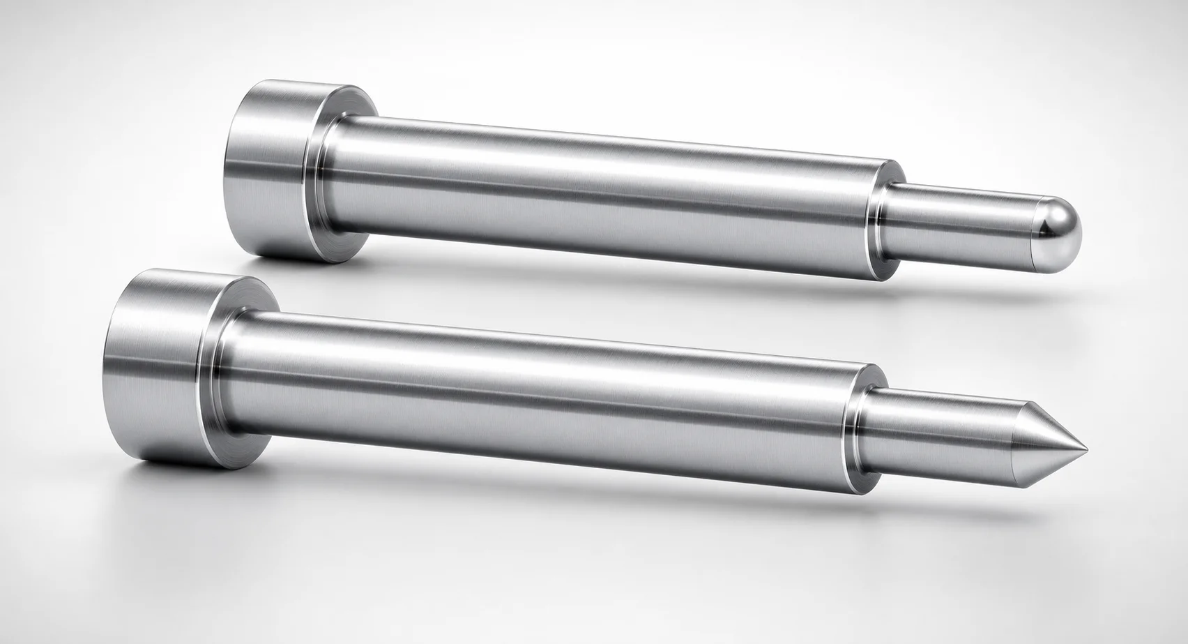
SKH51 Steel One-Step Core Pins
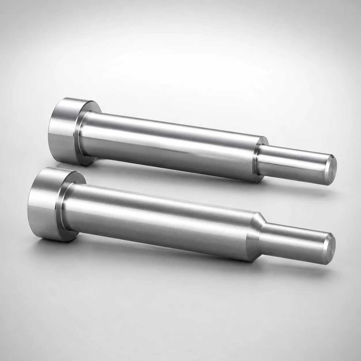
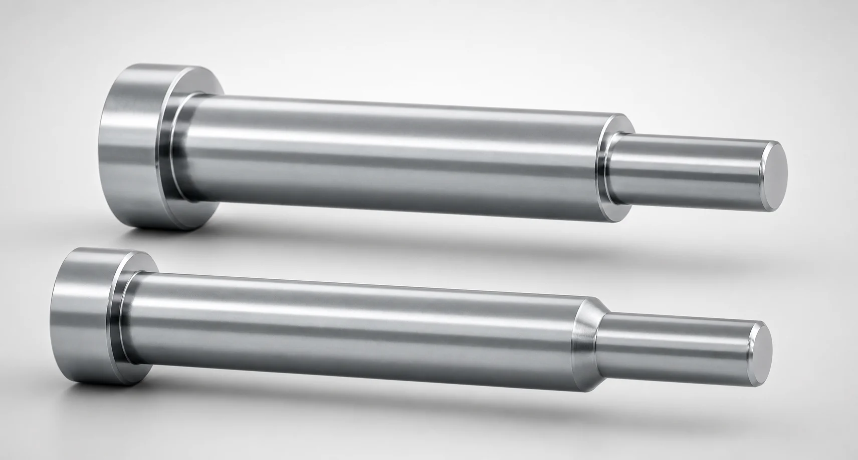
One-step core pins (SKH51 steel) are engineered for extra-precision mold alignment with selectable shaft diameter options. The one-step geometry simplifies core locating while supporting consistent ejection performance.
- One-step core pin design with no second step for straightforward locating in mold cavities
- SKH51 hardened steel construction delivers strong wear resistance for long production runs
- Extra-precision dimensional control to support repeatable assembly fit and stable core positioning
- Suitable for precision injection molds requiring reliable core pin engagement
Specifications
1918 configurations available
| L Dimension Tolerance | A/AAC (Tip Diameter) (mm) | D/P (Shaft Diameter) (mm) | First Step Shape | Tip Shape | C (Step type taper width) (mm) | CVC (C dimension can be designated at 0.01mm increments) (mm) | F (Bearing bore length) (mm) | FC (Makes F dimension shorter than F min) (mm) | G (Tip C chamfering width) (mm) | K (Tip angle) (°) | L (L dimension) (mm) | Q (Tip R chamfering) (mm) | R (Step type R) (mm) | S (Tip tapered width) (mm) | type |
|---|---|---|---|---|---|---|---|---|---|---|---|---|---|---|---|
| 0/-0.05 | 0.5 ~ 0.999 | 1 | B | B | - | - | 12 ~ 99.6 | - | - | - | 6.5 ~ 100 | - | - | - | - |
| 0/-0.05 | 0.4 ~ 0.49 | 1 | B | B | - | - | 12 ~ 99.6 | - | - | - | 6.5 ~ 100 | - | - | - | - |
| 0/-0.05 | 0.5 ~ 0.999 | 1 | B | B | - | - | - | 5 ~ 11.99 | - | - | 6.5 ~ 100 | - | - | - | - |
| 0/-0.05 | 0.4 ~ 0.49 | 1 | B | B | - | - | - | 5 ~ 11.99 | - | - | 6.5 ~ 100 | - | - | - | - |
| 0/-0.05 | 0.5 ~ 1.499 | 1.5 | B | B | - | - | 12 ~ 99.6 | - | - | - | 14 ~ 100 | - | - | - | - |
| 0/-0.05 | 0.4 ~ 0.49 | 1.5 | B | B | - | - | 12 ~ 99.6 | - | - | - | 14 ~ 100 | - | - | - | - |
| 0/-0.05 | 0.5 ~ 1.499 | 1.5 | B | B | - | - | - | 5 ~ 11.99 | - | - | 14 ~ 100 | - | - | - | - |
| 0/-0.05 | 0.4 ~ 0.49 | 1.5 | B | B | - | - | - | 5 ~ 11.99 | - | - | 14 ~ 100 | - | - | - | - |
| 0/-0.05 | 0.5 ~ 1.999 | 2 | B | B | - | - | 12 ~ 99.6 | - | - | - | 6.5 ~ 100 | - | - | - | - |
| 0/-0.05 | 0.5 ~ 0.69 | 2 | B | B | - | - | 12 ~ 99.6 | - | - | - | 6.5 ~ 100 | - | - | - | - |
| 0/-0.05 | 0.5 ~ 1.999 | 2 | B | B | - | - | - | 5 ~ 11.99 | - | - | 6.5 ~ 100 | - | - | - | - |
| 0/-0.05 | 0.5 ~ 0.69 | 2 | B | B | - | - | - | 5 ~ 11.99 | - | - | 6.5 ~ 100 | - | - | - | - |
| 0/-0.05 | 0.5 ~ 2.499 | 2.5 | B | B | - | - | 12 ~ 99.6 | - | - | - | 6.5 ~ 100 | - | - | - | - |
| 0/-0.05 | 0.5 ~ 0.69 | 2.5 | B | B | - | - | 12 ~ 99.6 | - | - | - | 6.5 ~ 100 | - | - | - | - |
| 0/-0.05 | 0.5 ~ 2.499 | 2.5 | B | B | - | - | - | 5 ~ 11.99 | - | - | 6.5 ~ 100 | - | - | - | - |
| 0/-0.05 | 0.5 ~ 0.69 | 2.5 | B | B | - | - | - | 5 ~ 11.99 | - | - | 6.5 ~ 100 | - | - | - | - |
| 0/-0.05 | 0.7 ~ 2.999 | 3 | B | B | - | - | 12 ~ 99.6 | - | - | - | 6.5 ~ 100 | - | - | - | - |
| 0/-0.05 | 0.7 ~ 0.99 | 3 | B | B | - | - | 12 ~ 99.6 | - | - | - | 6.5 ~ 100 | - | - | - | - |
| 0/-0.05 | 0.7 ~ 2.999 | 3 | B | B | - | - | - | 5 ~ 11.99 | - | - | 6.5 ~ 100 | - | - | - | - |
| 0/-0.05 | 0.7 ~ 0.99 | 3 | B | B | - | - | - | 5 ~ 11.99 | - | - | 6.5 ~ 100 | - | - | - | - |
| 0/-0.05 | 1 ~ 3.499 | 3.5 | B | B | - | - | 12 ~ 99.6 | - | - | - | 6.5 ~ 100 | - | - | - | - |
| 0/-0.05 | 0.7 ~ 0.99 | 3.5 | B | B | - | - | 12 ~ 99.6 | - | - | - | 6.5 ~ 100 | - | - | - | - |
| 0/-0.05 | 1 ~ 3.499 | 3.5 | B | B | - | - | - | 5 ~ 11.99 | - | - | 6.5 ~ 100 | - | - | - | - |
| 0/-0.05 | 0.7 ~ 0.99 | 3.5 | B | B | - | - | - | 5 ~ 11.99 | - | - | 6.5 ~ 100 | - | - | - | - |
| 0/-0.05 | 1 ~ 3.999 | 4 | B | B | - | - | 12 �� 99.6 | - | - | - | 6.5 ~ 100 | - | - | - | - |
| 0/-0.05 | 0.7 ~ 0.99 | 4 | B | B | - | - | 12 ~ 99.6 | - | - | - | 6.5 ~ 100 | - | - | - | - |
| 0/-0.05 | 1 ~ 3.999 | 4 | B | B | - | - | - | 5 ~ 11.99 | - | - | 6.5 ~ 100 | - | - | - | - |
| 0/-0.05 | 0.7 ~ 0.99 | 4 | B | B | - | - | - | 5 ~ 11.99 | - | - | 6.5 ~ 100 | - | - | - | - |
| 0/-0.05 | 1 ~ 4.499 | 4.5 | B | B | - | - | 12 ~ 99.6 | - | - | - | 6.5 ~ 100 | - | - | - | - |
| 0/-0.05 | 1 ~ 1.49 | 4.5 | B | B | - | - | 12 ~ 99.6 | - | - | - | 6.5 ~ 100 | - | - | - | - |
| 0/-0.05 | 1 ~ 4.499 | 4.5 | B | B | - | - | - | 5 ~ 11.99 | - | - | 6.5 ~ 100 | - | - | - | - |
| 0/-0.05 | 1 ~ 1.49 | 4.5 | B | B | - | - | - | 5 ~ 11.99 | - | - | 6.5 ~ 100 | - | - | - | - |
| 0/-0.05 | 1 ~ 4.999 | 5 | B | B | - | - | 12 ~ 99.6 | - | - | - | 6.5 ~ 100 | - | - | - | - |
| 0/-0.05 | 1 ~ 1.49 | 5 | B | B | - | - | 12 ~ 99.6 | - | - | - | 6.5 ~ 100 | - | - | - | - |
| 0/-0.05 | 1 ~ 4.999 | 5 | B | B | - | - | - | 5 ~ 11.99 | - | - | 6.5 ~ 100 | - | - | - | - |
| 0/-0.05 | 1 ~ 1.49 | 5 | B | B | - | - | - | 5 ~ 11.99 | - | - | 6.5 ~ 100 | - | - | - | - |
| 0/-0.05 | 1.5 ~ 5.499 | 5.5 | B | B | - | - | 12 ~ 99.6 | - | - | - | 6.5 ~ 100 | - | - | - | - |
| 0/-0.05 | 1 ~ 1.49 | 5.5 | B | B | - | - | 12 ~ 99.6 | - | - | - | 6.5 ~ 100 | - | - | - | - |
| 0/-0.05 | 1.5 ~ 5.499 | 5.5 | B | B | - | - | - | 5 ~ 11.99 | - | - | 6.5 ~ 100 | - | - | - | - |
| 0/-0.05 | 1 ~ 1.49 | 5.5 | B | B | - | - | - | 5 ~ 11.99 | - | - | 6.5 ~ 100 | - | - | - | - |
| 0/-0.05 | 2 ~ 5.999 | 6 | B | B | - | - | 12 ~ 99.6 | - | - | - | 6.5 ~ 100 | - | - | - | - |
| 0/-0.05 | 1.5 ~ 1.99 | 6 | B | B | - | - | 12 ~ 99.6 | - | - | - | 6.5 ~ 100 | - | - | - | - |
| 0/-0.05 | 2 ~ 5.999 | 6 | B | B | - | - | - | 5 ~ 11.99 | - | - | 6.5 ~ 100 | - | - | - | - |
| 0/-0.05 | 1.5 ~ 1.99 | 6 | B | B | - | - | - | 5 ~ 11.99 | - | - | 6.5 ~ 100 | - | - | - | - |
| 0/-0.05 | 2 ~ 6.499 | 6.5 | B | B | - | - | 12 ~ 99.6 | - | - | - | 6.5 ~ 100 | - | - | - | - |
| 0/-0.05 | 1.5 ~ 1.99 | 6.5 | B | B | - | - | 12 ~ 99.6 | - | - | - | 6.5 ~ 100 | - | - | - | - |
| 0/-0.05 | 2 ~ 6.499 | 6.5 | B | B | - | - | - | 5 ~ 11.99 | - | - | 6.5 ~ 100 | - | - | - | - |
| 0/-0.05 | 1.5 ~ 1.99 | 6.5 | B | B | - | - | - | 5 ~ 11.99 | - | - | 6.5 ~ 100 | - | - | - | - |
| 0/-0.05 | 2 ~ 6.999 | 7 | B | B | - | - | 12 ~ 99.6 | - | - | - | 6.5 ~ 100 | - | - | - | - |
| 0/-0.05 | 1.5 ~ 1.99 | 7 | B | B | - | - | 12 ~ 99.6 | - | - | - | 6.5 ~ 100 | - | - | - | - |
Product Guide
Application Scenarios+
This one-step core pin is used to achieve extra-precision alignment between mold halves in injection mold tooling, where stable positioning directly improves part-to-part repeatability.
- Automotive connector & terminal molds: The selectable shaft diameter (1–13 mm) helps match the core engagement area for consistent core pin contact under high cycle loads, supporting reliable ejection and reduced dimensional drift over long runs.
- Electronics housings and fine-feature plastics: The one-step geometry (no second step) simplifies cavity/core locating and can streamline assembly, while the hardened SKH51 steel construction improves wear resistance at the tip and bearing bore interfaces.
- Medical device component housings: Extra-precision dimensional control supports stable core positioning, helping minimize misalignment that can affect thin ribs, sealing features, or cosmetic surfaces.
The hardened SKH51 variant is especially suited for these applications because it balances wear resistance for continuous production with enough toughness for stable core pin engagement.
Material & Process Details+
SKH51 steel is a hardened tool steel grade used for precision mold components requiring high surface durability. In industrial practice, SKH51 is commonly aligned with the AISI M2 high-speed steel family, providing strong wear resistance under sliding contact.
- Hardness: Core pins in hardened SKH51 are intended for stable hardness after heat treatment; typical tool-steel performance targets are in the ~60 HRC class range (confirm exact lot hardness if you have a receiving spec).
- Heat treatment: Generally supplied as quenched & tempered or equivalent hardening condition for dimensional stability prior to grinding.
- Performance trade-off: Higher hardness improves wear resistance at the tip and bearing bore, but can reduce toughness if overhardened—precise heat treatment and controlled finishing help maintain core pin robustness.
Compared with softer structural steels, hardened SKH51 offers better wear life for long production cycles; compared with lower-alloy hardened grades, it typically provides superior abrasion resistance for precision locating interfaces.
Sizing & Selection Guide+
Select the core pin dimensions by matching the pin’s engagement geometry to the mold’s cavity/core locating requirements and the mating bore/feature size.
- Shaft (D/P) diameter: Choose from 1–13 mm. This diameter should match the mold’s supporting bore size for stable guidance without excessive clearance.
- Tip/ending geometry: Use the A/AAC tip diameter (0.4–2 mm) with the specified tip shape (B, C, G, R, S, T) and K tip angle (21–60° or 1–45° depending on option) to ensure correct contact behavior.
- Length (L): For 6.5–100 mm (or 14–100 mm depending on configuration), pick a length that provides sufficient engagement through the mating core/cavity while avoiding interference.
- Tolerance & fit: The L dimension tolerance is 0/-0.05, +0.01/0, so verify assembly stack-up when you are optimizing for minimal play.
Where applicable, confirm whether optional increments (e.g., CVC in 0.01 mm steps with ranges 0.1–1) are needed for your mold’s target clearance and alignment strategy.
Frequently Asked Questions
Which shaft diameter range (D/P) can I select for stable one-step core pin positioning?+
How do I choose the correct length (L) given the tolerance requirements for assembly stack-up?+
What tip geometry parameters control contact behavior at the core locating interface?+
Why does the one-step design (no second step) matter for mold assembly and ejection performance?+
What heat-treatment state should I expect for SKH51 core pins, and how does it affect wear vs. toughness?+
Related Products
Need Custom Specifications?
Our engineering team can help with custom configurations, material selection, and volume pricing.