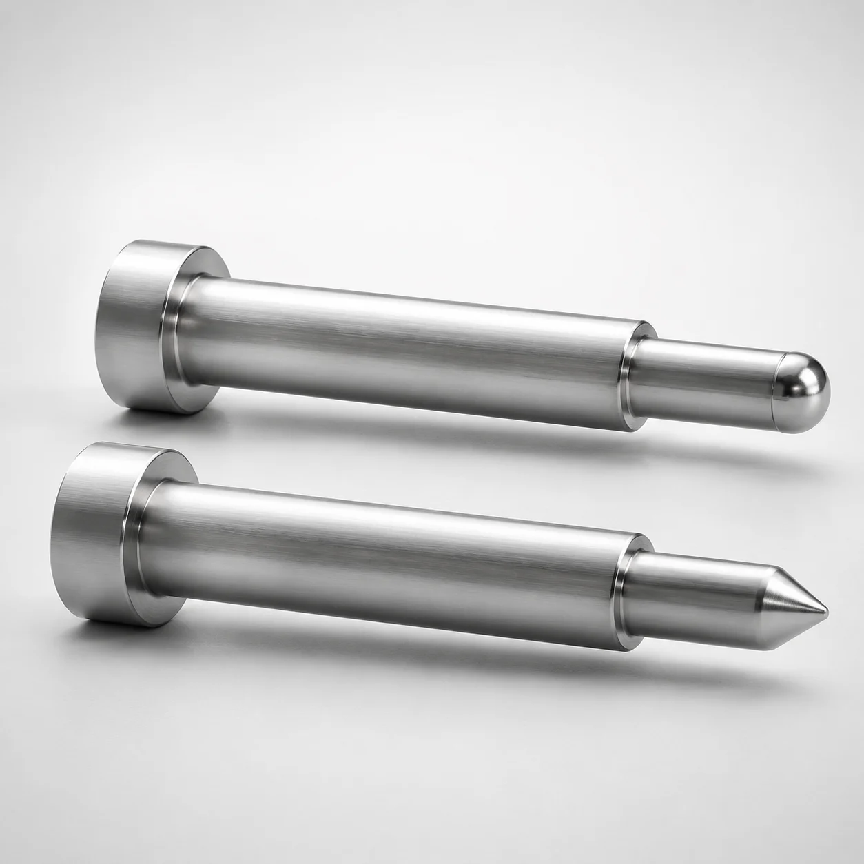
One-Step Core Pins No Second Step
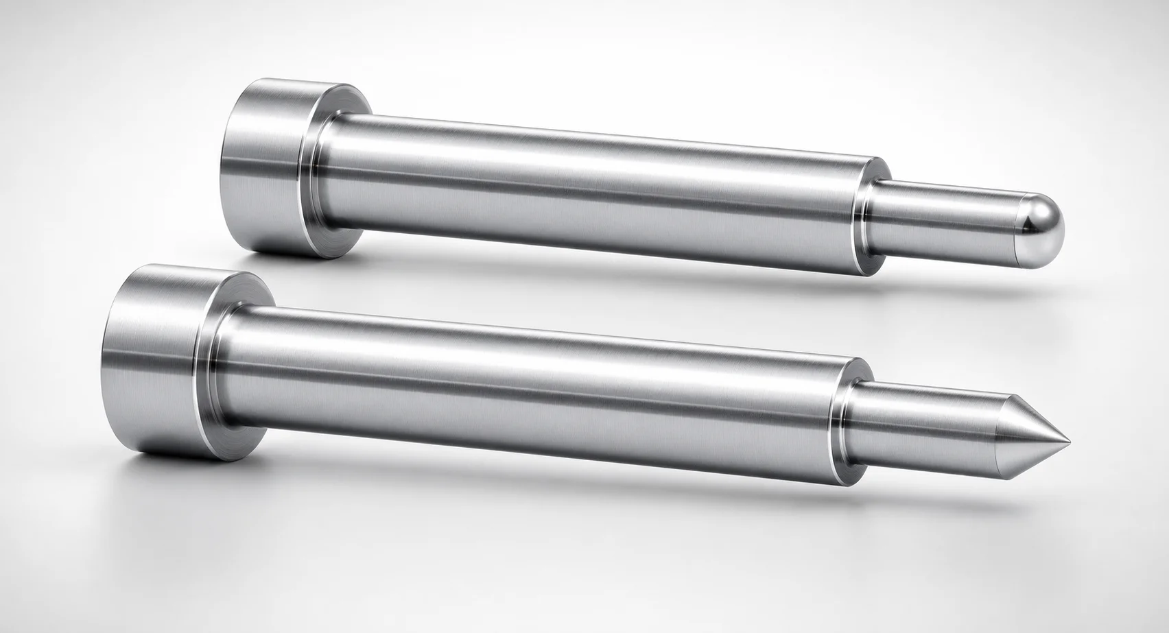
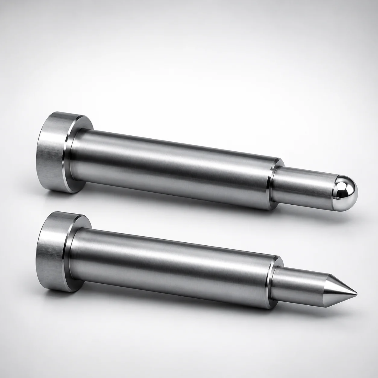
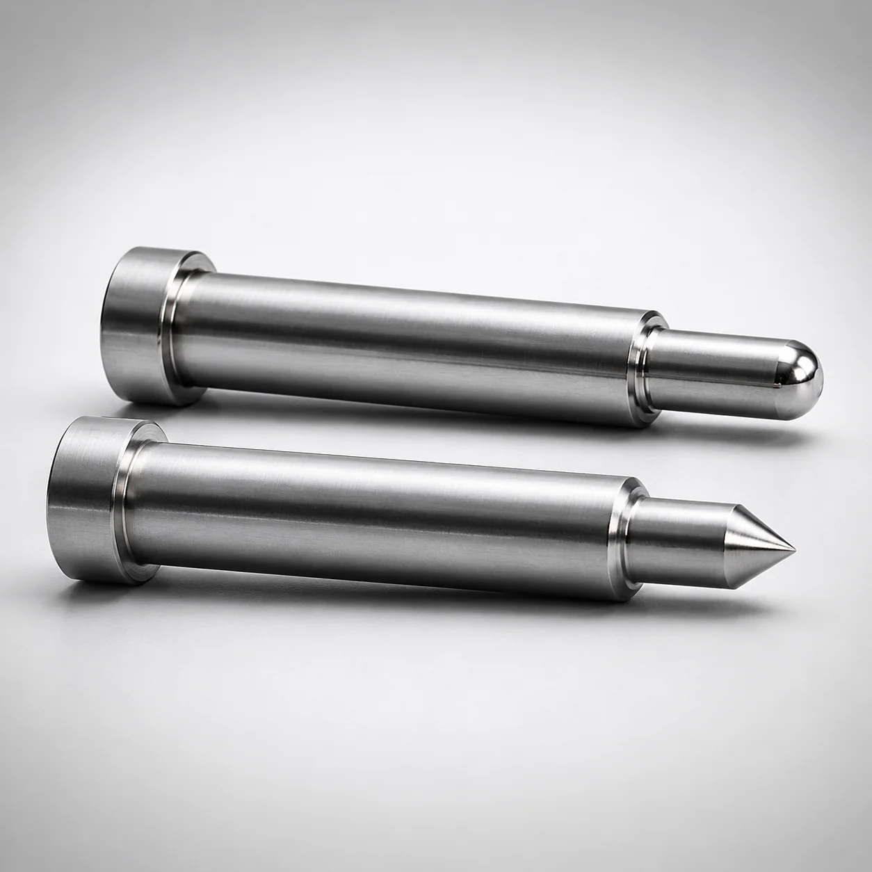
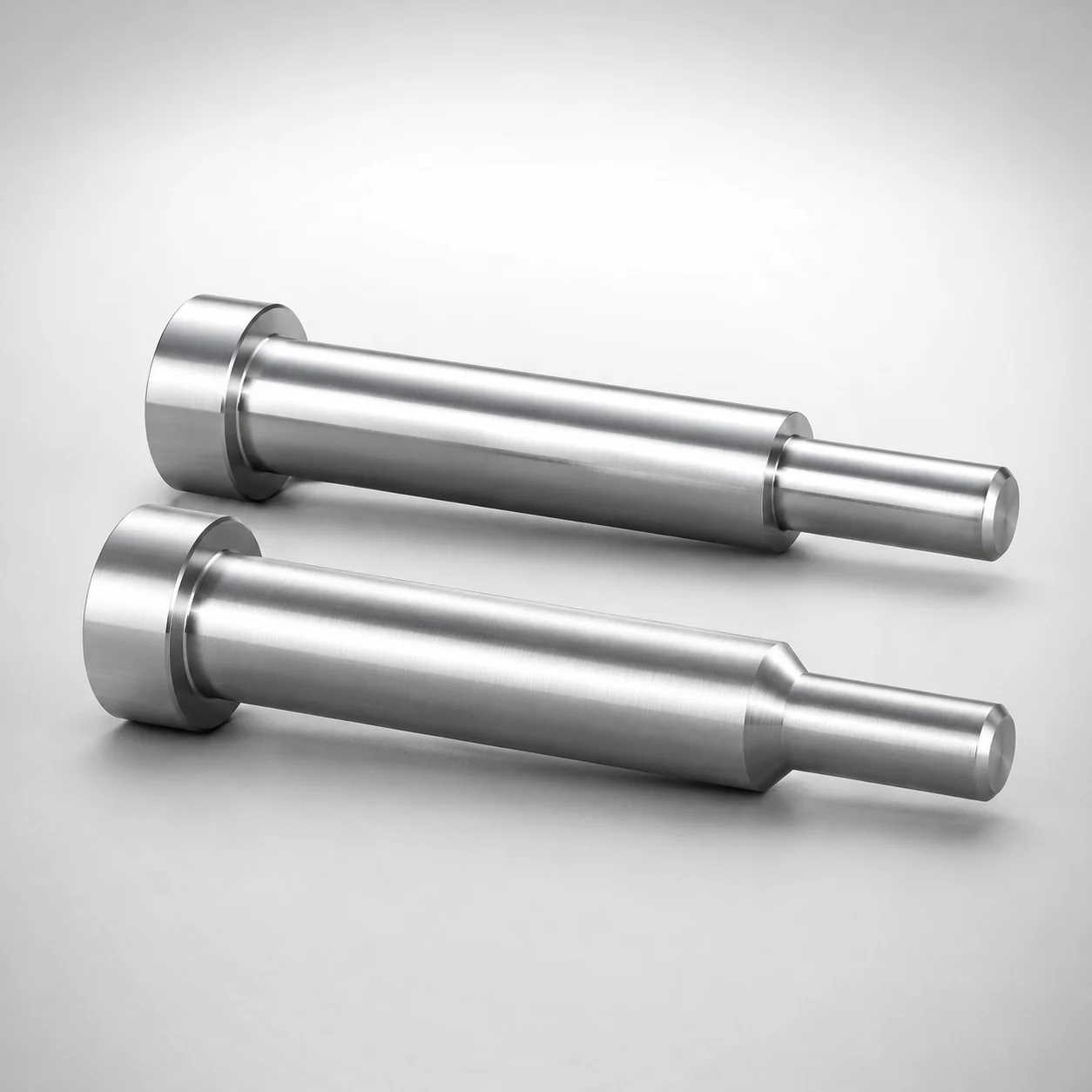
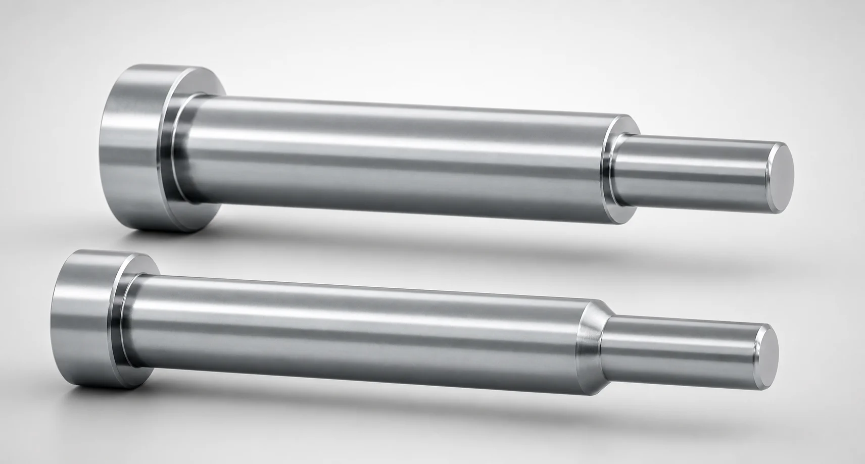
One-step core pins (SKH51/DK61 steel) are precision taperless locating components designed for one-stage positioning in the mold. The one-step geometry with no second step supports consistent seating for reliable ejection and repeatable alignment.
- One-stage one-step core design with no second step for stable mold alignment
- Made from hardened steel alloys to improve wear resistance in production cycles
- Built for tight shaft and tip tolerance requirements to maintain assembly accuracy
- Suitable for precision mold core and cavity applications requiring taperless locating
Specifications
4320 configurations available
| Material | L Dimension Tolerance | A/AAC (Tip Diameter) (mm) | D/P (Shaft Diameter) (mm) | First Step Shape | Tip Shape | C (Step type taper width) (mm) | CVC (C dimension can be designated at 0.01mm increments) (mm) | F (Bearing bore length) (mm) | FC (Makes F dimension shorter than F min) (mm) | G (Tip C chamfering width) (mm) | K (Tip angle) (°) | L (L dimension) (mm) | Q (Tip R chamfering) (mm) | R (Step type R) (mm) | S (Tip tapered width) (mm) | type |
|---|---|---|---|---|---|---|---|---|---|---|---|---|---|---|---|---|
| SKH51 | 0/-0.05 | 0.5 ~ 0.99 | 1 | B | B | - | - | 12 ~ 99.4 | - | - | - | 6.5 ~ 100 | - | - | - | - |
| SKH51 | 0/-0.05 | 0.4 ~ 0.49 | 1 | B | B | - | - | 12 ~ 99.4 | - | - | - | 6.5 ~ 100 | - | - | - | - |
| SKH51 | 0/-0.05 | 0.5 ~ 0.99 | 1 | B | B | - | - | - | 5 ~ 13.39 | - | - | 6.5 ~ 100 | - | - | - | - |
| SKH51 | 0/-0.05 | 0.4 ~ 0.49 | 1 | B | B | - | - | - | 5 ~ 13.39 | - | - | 6.5 ~ 100 | - | - | - | - |
| SKH51 | 0/-0.05 | 0.5 ~ 1.49 | 1.5 | B | B | - | - | 12 ~ 99.4 | - | - | - | 6.5 ~ 100 | - | - | - | - |
| SKH51 | 0/-0.05 | 0.4 ~ 0.49 | 1.5 | B | B | - | - | 12 ~ 99.4 | - | - | - | 6.5 ~ 100 | - | - | - | - |
| SKH51 | 0/-0.05 | 0.5 ~ 1.49 | 1.5 | B | B | - | - | - | 5 ~ 13.39 | - | - | 6.5 ~ 100 | - | - | - | - |
| SKH51 | 0/-0.05 | 0.4 ~ 0.49 | 1.5 | B | B | - | - | - | 5 ~ 13.39 | - | - | 6.5 ~ 100 | - | - | - | - |
| SKH51 | 0/-0.05 | 0.5 ~ 1.99 | 2 | B | B | - | - | 12 ~ 99.4 | - | - | - | 6.5 ~ 100 | - | - | - | - |
| SKH51 | 0/-0.05 | 0.5 ~ 0.69 | 2 | B | B | - | - | 12 ~ 99.4 | - | - | - | 6.5 ~ 100 | - | - | - | - |
| SKH51 | 0/-0.05 | 0.5 ~ 1.99 | 2 | B | B | - | - | - | 5 ~ 13.39 | - | - | 6.5 ~ 100 | - | - | - | - |
| SKH51 | 0/-0.05 | 0.5 ~ 0.69 | 2 | B | B | - | - | - | 5 ~ 13.39 | - | - | 6.5 ~ 100 | - | - | - | - |
| SKH51 | 0/-0.05 | 0.5 ~ 2.49 | 2.5 | B | B | - | - | 12 ~ 99.4 | - | - | - | 6.5 ~ 100 | - | - | - | - |
| SKH51 | 0/-0.05 | 0.5 ~ 0.69 | 2.5 | B | B | - | - | 12 ~ 99.4 | - | - | - | 6.5 ~ 100 | - | - | - | - |
| SKH51 | 0/-0.05 | 0.5 ~ 2.49 | 2.5 | B | B | - | - | - | 5 ~ 13.39 | - | - | 6.5 ~ 100 | - | - | - | - |
| SKH51 | 0/-0.05 | 0.5 ~ 0.69 | 2.5 | B | B | - | - | - | 5 ~ 13.39 | - | - | 6.5 ~ 100 | - | - | - | - |
| SKH51 | 0/-0.05 | 0.7 ~ 2.99 | 3 | B | B | - | - | 12 ~ 99.4 | - | - | - | 6.5 ~ 100 | - | - | - | - |
| SKH51 | 0/-0.05 | 0.7 ~ 0.99 | 3 | B | B | - | - | 12 ~ 99.4 | - | - | - | 6.5 ~ 100 | - | - | - | - |
| SKH51 | 0/-0.05 | 0.7 ~ 2.99 | 3 | B | B | - | - | - | 5 ~ 13.39 | - | - | 6.5 ~ 100 | - | - | - | - |
| SKH51 | 0/-0.05 | 0.7 ~ 0.99 | 3 | B | B | - | - | - | 5 ~ 13.39 | - | - | 6.5 ~ 100 | - | - | - | - |
| SKH51 | 0/-0.05 | 1 ~ 3.49 | 3.5 | B | B | - | - | 12 ~ 119.4 | - | - | - | 6.5 ~ 120 | - | - | - | - |
| SKH51 | 0/-0.05 | 0.7 ~ 0.99 | 3.5 | B | B | - | - | 12 ~ 119.4 | - | - | - | 6.5 ~ 120 | - | - | - | - |
| SKH51 | 0/-0.05 | 1 ~ 3.49 | 3.5 | B | B | - | - | - | 5 ~ 13.39 | - | - | 6.5 ~ 120 | - | - | - | - |
| SKH51 | 0/-0.05 | 0.7 ~ 0.99 | 3.5 | B | B | - | - | - | 5 ~ 13.39 | - | - | 6.5 ~ 120 | - | - | - | - |
| SKH51 | 0/-0.05 | 1 ~ 3.99 | 4 | B | B | - | - | 12 ~ 119.4 | - | - | - | 6.5 ~ 120 | - | - | - | - |
| SKH51 | 0/-0.05 | 0.7 ~ 0.99 | 4 | B | B | - | - | 12 ~ 119.4 | - | - | - | 6.5 ~ 120 | - | - | - | - |
| SKH51 | 0/-0.05 | 1 ~ 3.99 | 4 | B | B | - | - | - | 5 ~ 13.39 | - | - | 6.5 ~ 120 | - | - | - | - |
| SKH51 | 0/-0.05 | 0.7 ~ 0.99 | 4 | B | B | - | - | - | 5 ~ 13.39 | - | - | 6.5 ~ 120 | - | - | - | - |
| SKH51 | 0/-0.05 | 1 ~ 4.49 | 4.5 | B | B | - | - | 12 ~ 119.4 | - | - | - | 6.5 ~ 120 | - | - | - | - |
| SKH51 | 0/-0.05 | 1 ~ 1.49 | 4.5 | B | B | - | - | 12 ~ 119.4 | - | - | - | 6.5 ~ 120 | - | - | - | - |
| SKH51 | 0/-0.05 | 1 ~ 4.49 | 4.5 | B | B | - | - | - | 5 ~ 13.39 | - | - | 6.5 ~ 120 | - | - | - | - |
| SKH51 | 0/-0.05 | 1 ~ 1.49 | 4.5 | B | B | - | - | - | 5 ~ 13.39 | - | - | 6.5 ~ 120 | - | - | - | - |
| SKH51 | 0/-0.05 | 1 ~ 4.99 | 5 | B | B | - | - | 12 ~ 150 | - | - | - | 6.5 ~ 150 | - | - | - | - |
| SKH51 | 0/-0.05 | 1 ~ 1.49 | 5 | B | B | - | - | 12 ~ 150 | - | - | - | 6.5 ~ 150 | - | - | - | - |
| SKH51 | 0/-0.05 | 1 ~ 4.99 | 5 | B | B | - | - | - | 5 ~ 13.39 | - | - | 6.5 ~ 150 | - | - | - | - |
| SKH51 | 0/-0.05 | 1 ~ 1.49 | 5 | B | B | - | - | - | 5 ~ 13.39 | - | - | 6.5 ~ 150 | - | - | - | - |
| SKH51 | 0/-0.05 | 1.5 ~ 5.49 | 5.5 | B | B | - | - | 12 ~ 150 | - | - | - | 6.5 ~ 150 | - | - | - | - |
| SKH51 | 0/-0.05 | 1 ~ 1.49 | 5.5 | B | B | - | - | 12 ~ 150 | - | - | - | 6.5 ~ 150 | - | - | - | - |
| SKH51 | 0/-0.05 | 1.5 ~ 5.49 | 5.5 | B | B | - | - | - | 5 ~ 13.39 | - | - | 6.5 ~ 150 | - | - | - | - |
| SKH51 | 0/-0.05 | 1 ~ 1.49 | 5.5 | B | B | - | - | - | 5 ~ 13.39 | - | - | 6.5 ~ 150 | - | - | - | - |
| SKH51 | 0/-0.05 | 2 ~ 5.99 | 6 | B | B | - | - | 12 ~ 150 | - | - | - | 6.5 ~ 150 | - | - | - | - |
| SKH51 | 0/-0.05 | 1.5 ~ 1.99 | 6 | B | B | - | - | 12 ~ 150 | - | - | - | 6.5 ~ 150 | - | - | - | - |
| SKH51 | 0/-0.05 | 2 ~ 5.99 | 6 | B | B | - | - | - | 5 ~ 13.39 | - | - | 6.5 ~ 150 | - | - | - | - |
| SKH51 | 0/-0.05 | 1.5 ~ 1.99 | 6 | B | B | - | - | - | 5 ~ 13.39 | - | - | 6.5 ~ 150 | - | - | - | - |
| SKH51 | 0/-0.05 | 2 ~ 6.49 | 6.5 | B | B | - | - | 12 ~ 150 | - | - | - | 6.5 ~ 150 | - | - | - | - |
| SKH51 | 0/-0.05 | 1.5 ~ 1.99 | 6.5 | B | B | - | - | 12 ~ 150 | - | - | - | 6.5 ~ 150 | - | - | - | - |
| SKH51 | 0/-0.05 | 2 ~ 6.49 | 6.5 | B | B | - | - | - | 5 ~ 13.39 | - | - | 6.5 ~ 150 | - | - | - | - |
| SKH51 | 0/-0.05 | 1.5 ~ 1.99 | 6.5 | B | B | - | - | - | 5 ~ 13.39 | - | - | 6.5 ~ 150 | - | - | - | - |
| SKH51 | 0/-0.05 | 2 ~ 6.99 | 7 | B | B | - | - | 12 ~ 150 | - | - | - | 6.5 ~ 150 | - | - | - | - |
| SKH51 | 0/-0.05 | 1.5 ~ 1.99 | 7 | B | B | - | - | 12 ~ 150 | - | - | - | 6.5 ~ 150 | - | - | - | - |
Product Guide
Application Scenarios+
One-step, taperless core pins are used in injection mold tooling when the core needs to be located in a single, controlled seating event. Their no second step geometry supports consistent contact and positioning, helping maintain repeatable core alignment through repeated molding cycles.
- Automotive connector housings: In multi-cavity molds, taperless one-stage locating reduces misalignment during core movement, supporting stable part geometry and ejection repeatability.
- Medical device housings and small precision parts: For tight assembly accuracy requirements, the one-stage configuration helps ensure predictable core positioning, reducing downstream variation in wall thickness and feature locations.
- Electronics and optical component molds: When fine tip/bearing dimensions are required for controlled guidance, hardened steel variants help resist wear that can otherwise degrade locating accuracy over production.
These applications benefit from the availability of hardened SKH51/DK61 steel options and the product’s taperless, one-step design for stable alignment without a secondary seating phase.
Material & Process Details+
This product is available in SKH51 and SKD61 hardened steel variants, both selected to maintain dimensional stability and wear resistance in core/cavity locating service.
- SKH51 (HSS-based, commonly AISI M2-equivalent): Typically used where higher hot hardness and wear resistance are prioritized. The trade-off is that toughness and machinability can be more challenging than lower-alloy tool steels if the pin sees high impact loads.
- SKD61 (H13-equivalent): Often selected for a strong balance of toughness and thermal fatigue resistance for general hot-work tooling. Wear resistance is excellent, though the exact durability depends on surface finish and operating temperature.
In both cases, the pins are supplied in a hardened steel state to improve wear life. Because the load path is localization/contact-based, maintaining hardness supports consistent seating and reduces the drift of tip/bearing dimensions during production.
Sizing & Selection Guide+
Select the core pin dimensions by matching the pin’s shaft diameter (D/P = 1–20 mm) and tip diameter (A/AAC = 0.4–5 mm) to the mating bore and guiding features in the mold core or cavity.
- Length (L): Choose from the provided ranges such as 6.5–100 mm, 6.5–120 mm, 6.5–150 mm, or 14–150 mm depending on your mold thickness/stack-up. Ensure the pin bearing length (F) falls within the specified options (e.g., 12–99.4, 12–119.4, up to 28–150).
- Tip and step geometry: Use the available tip/shape combinations (First Step Shapes: B, C, D, E; Tip Shapes: B, C, G, R, S, T) to align with your taperless seating pocket.
- Tolerance fit: For L dimension tolerance, use the two stated bands: 0/-0.05 or +0.01/0. This affects preload/contact timing; verify clearance/fit for the bearing bore length (F) to prevent premature bottoming.
Most dimensions are configuration-based within the listed ranges; lock the shaft and tip diameters first, then finalize L/F to achieve controlled one-stage seating with no second step.
Frequently Asked Questions
How do SKH51 vs. SKD61 affect wear life for one-step taperless core pin locating?+
What shaft and tip diameter ranges are supported for this one-step core pin?+
Which L length range should I use when designing for a given mold stack-up?+
What tolerance options are available for the L dimension, and why does it matter?+
Can the tip/step geometry be customized for different taperless seating pocket shapes?+
Related Products
Need Custom Specifications?
Our engineering team can help with custom configurations, material selection, and volume pricing.