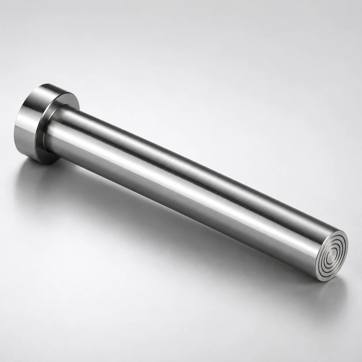
M2 Steel Gas Release Core Pins with Vent Filter
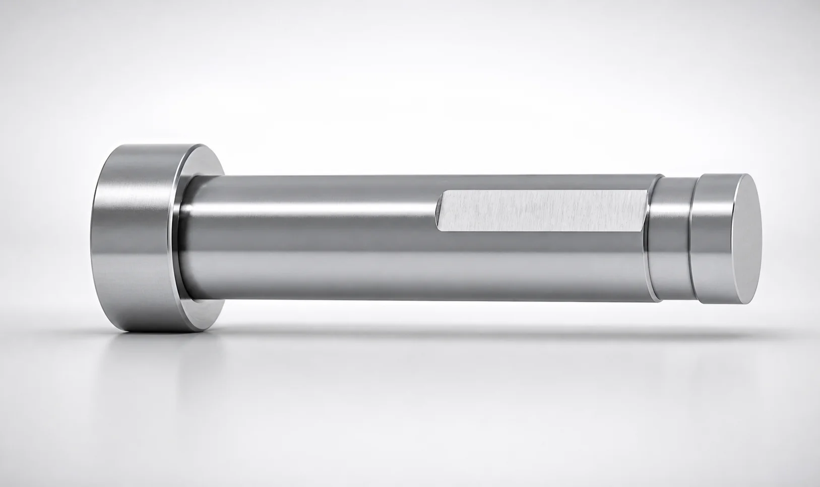
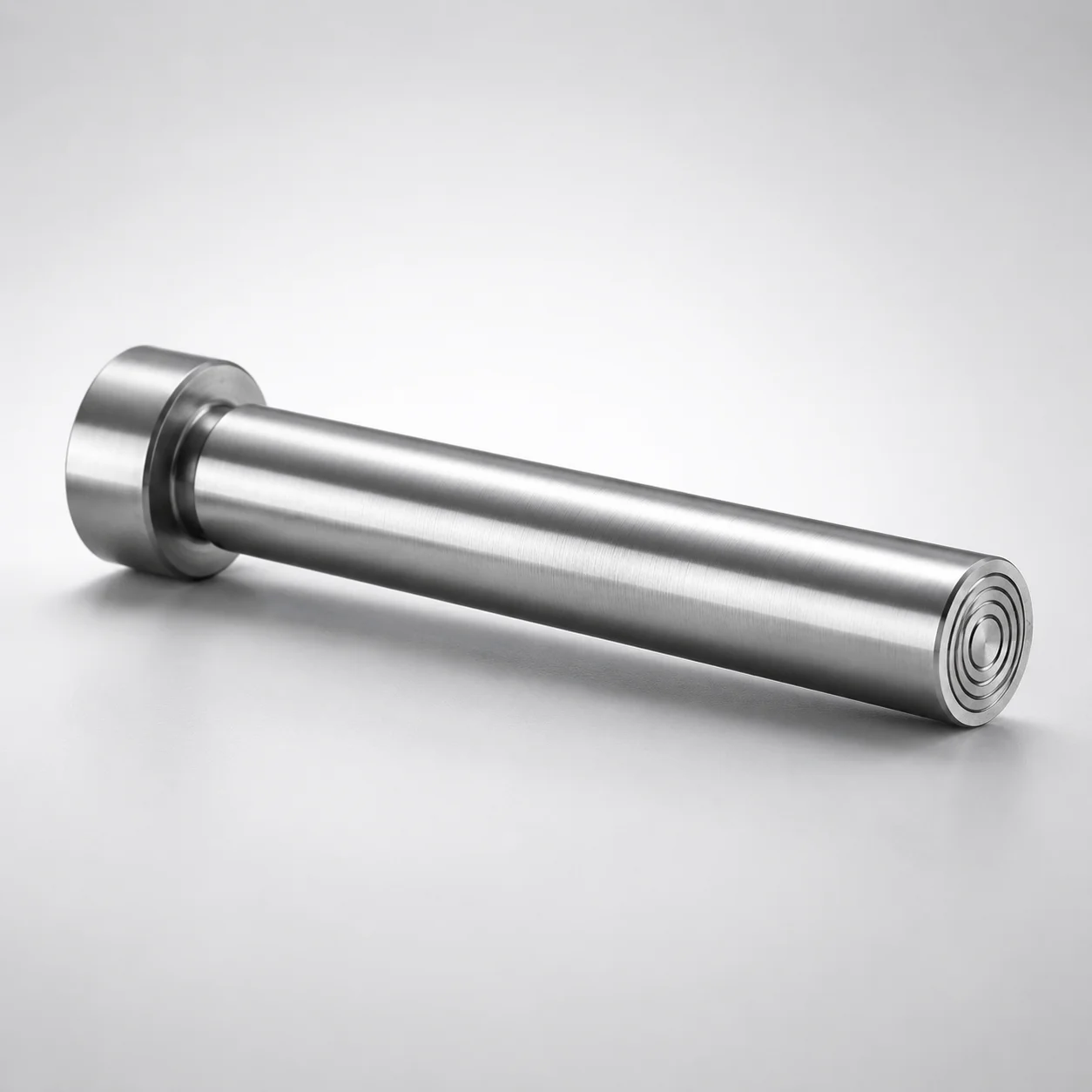
Gas release core pins with vent filter (M2 steel) use a pressed vent filter at the pin tip to route mold air out through built-in ventilation grooves. Concentric groove geometry supports consistent exhaust performance and helps reduce defects caused by installation orientation.
- Pressed vent filter at the pin tip creates an efficient gas vent path during molding
- Concentrically arranged ventilation grooves allow gas escape from any direction
- M2 steel construction with quenched hardening steel design supports wear resistance in die use
- Designed for core pin applications where stable venting improves repeatable mold filling
Specifications
8 configurations available
| D/P (Shaft diameter) (mm) | L (L dimension) (mm) | type |
|---|---|---|
| 3 | 15 ~ 100 | - |
| 4 | 15 ~ 100 | - |
| 5 | 15 ~ 100 | - |
| 6 | 15 ~ 100 | - |
| 3 | 15 ~ 100 | - |
| 4 | 15 ~ 100 | - |
| 5 | 15 ~ 100 | - |
| 6 | 15 ~ 100 | - |
Product Guide
Application Scenarios+
Used in straight core pin assemblies for plastic injection molds, this gas-release variant integrates a pressed vent filter at the pin tip to route trapped air out through built-in ventilation grooves. The concentric groove geometry helps exhaust gas uniformly regardless of installation orientation, supporting stable cavity pressure during filling.
- Automotive connector and housing molds: improves venting consistency in dense part geometries where knit lines, burn marks, or short shots can be triggered by trapped air near core surfaces.
- Appliance and enclosure components: supports repeatable mold filling for deeper ribs/feature cores by maintaining controlled air evacuation along the core pin region.
- General core-based venting inserts: suited when you need a compact gas path at the core interface without relocating external venting to the parting line.
The M2-steel, quenched hardened construction is appropriate for core pin duty where abrasion and long-term wear at the pin tip/vent interface affect vent performance.
Material & Process Details+
This core pin uses M2 tool steel in the quenched hardened condition for core wear resistance under repeated sliding/press-fit assembly and high-contact mold operation. M2 is widely associated with AISI M2 (high-speed steel family) chemistry, providing strong hot hardness and improved durability at the pin tip compared with lower alloy steels.
- Heat treatment: supplied in a quenched hardening steel state (hardness oriented for tool steels used in die and insert applications).
- Hardness & wear vs. toughness trade-off: quenched hard structures typically deliver higher wear resistance but require attention to shock loading; excessive impact can reduce toughness.
- Manufacturing: machined straight core pin blanks with tip grooving, followed by heat treatment, then functional finishing so the press-fit vent filter seats reliably at the pin end.
If you compare alternatives, lower-alloy core pin steels may be tougher but generally offer less wear resistance at the vent/filter interface, which can impact repeat vent consistency over cycles.
Sizing & Selection Guide+
Select the shaft diameter (D/P) to match the intended drilled bore size in the mold block and the core pin retention design. Available diameters are 3, 4, 5, and 6 mm, so choose the closest match to your core support hole and guide layout.
- Step 1 — Choose D/P: use D/P = 3–6 mm based on your core pin seat diameter and press-fit guidance. Verify that the bore and seating design are compatible with a press-fit at the pin tip where the vent filter is integrated.
- Step 2 — Choose L: set the overall length to your stack-up needs using L = 15 to 100 mm. Ensure the vent/filter region lands in the airflow path zone near the cavity interface.
- Step 3 — Fit and tolerance: press-fit interfaces require attention to manufacturing tolerances for concentricity and seating depth. If you must maintain a specific vent-to-cavity clearance, confirm that the selected L does not shift the vent grooves relative to the intended exhaust location.
D/P and L are fixed by the specification range; select among available sizes to achieve the required placement.
Frequently Asked Questions
What is the venting mechanism—does this core pin rely on external vents or an internal path at the tip?+
This variant uses a pressed vent filter at the pin tip to form the gas escape route during molding. The built-in ventilation grooves guide exhaust through the core pin region rather than requiring external venting on the parting line.
How does the concentric groove design affect exhaust uniformity and installation orientation?+
The ventilation grooves are arranged concentrically, enabling gas to escape from any direction relative to the core pin orientation. This helps maintain consistent venting performance even if the pin is installed without a specific rotational alignment.
Which shaft diameter (D/P) options are available, and how do I match them to my mold bore?+
Available D/P (shaft diameter) values are 3, 4, 5, and 6 mm. Select the diameter that matches your mold block bore and retention scheme for a press-fit style core pin assembly.
What length range (L) should be used to place the vent filter in the correct cavity area?+
The available L (overall length) range is 15 to 100 mm. Choose the length so the tip vent/filter zone sits at the intended exhaust location near the cavity/core interface, maintaining the required clearance and stack-up position.
Why is M2 steel selected for gas-release core pins compared with softer core pin materials?+
The product description specifies M2 steel and a quenched hardened steel design aimed at wear resistance in die/core use, particularly at the pin tip and vent/filter interface. Compared with lower-wear core steels, the higher durability supports more consistent vent performance over repeated cycles.
Related Products
Need Custom Specifications?
Our engineering team can help with custom configurations, material selection, and volume pricing.