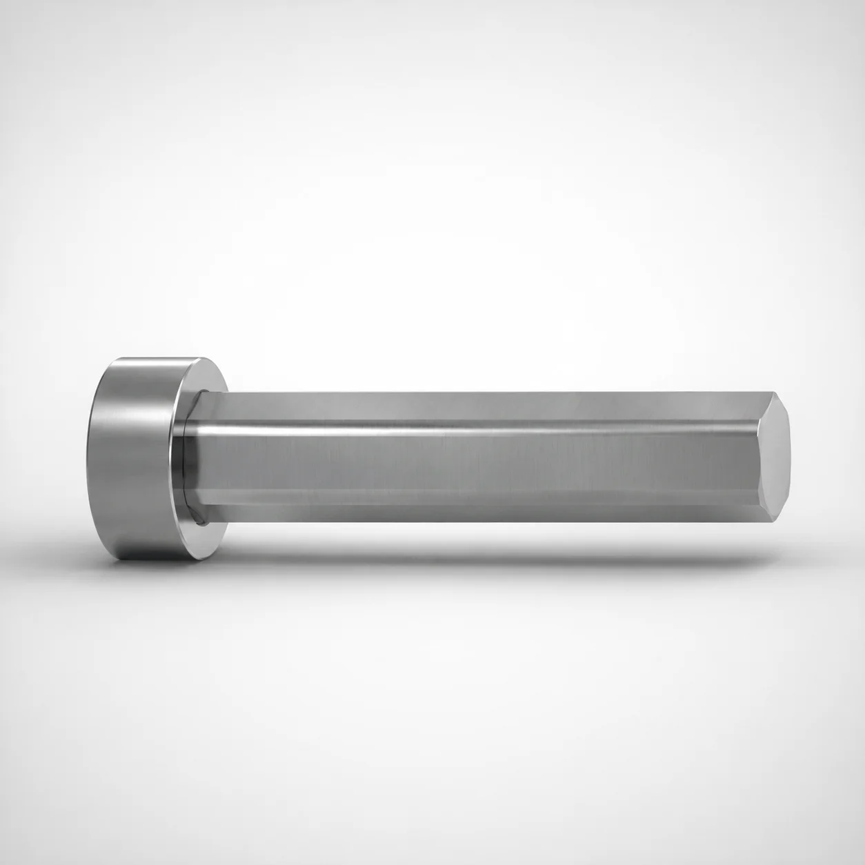
DIN Standard M2 Steel Gas Release Straight Core Pins Flat-Sided
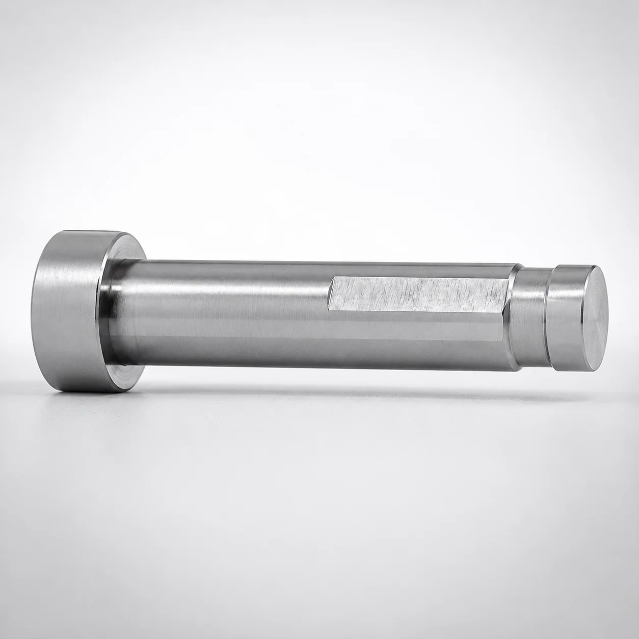
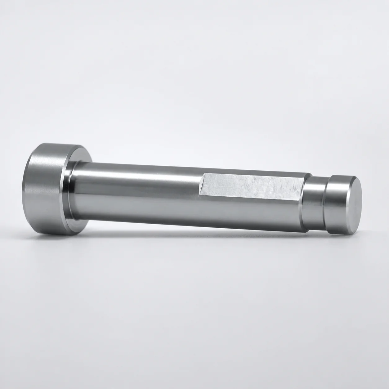
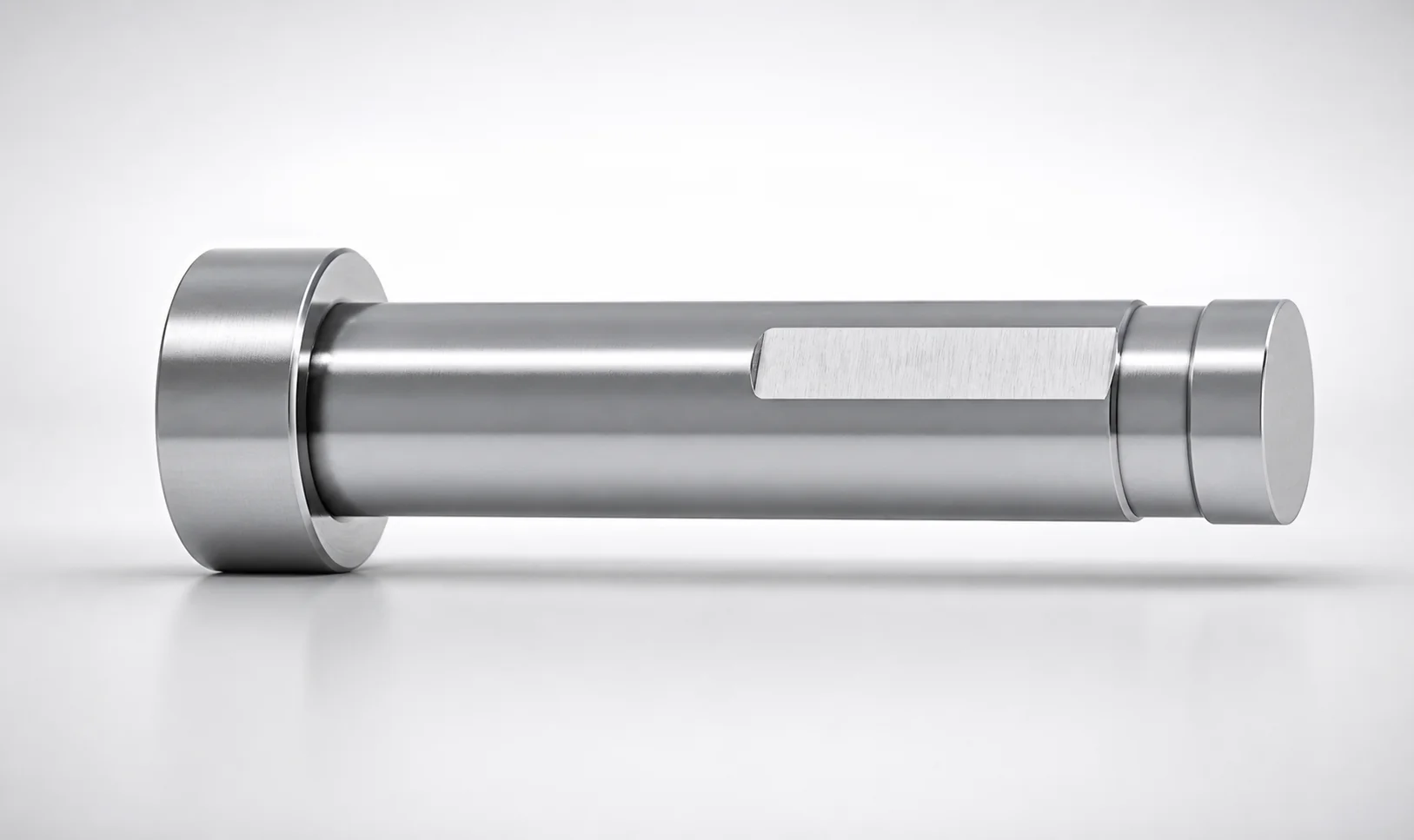
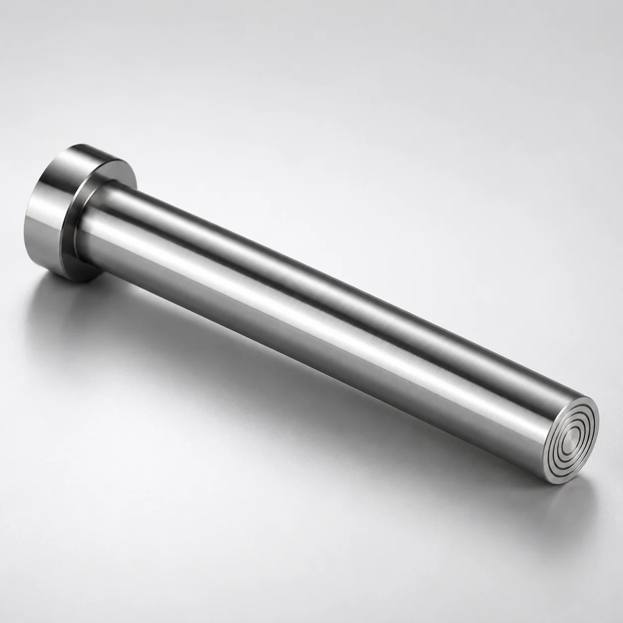
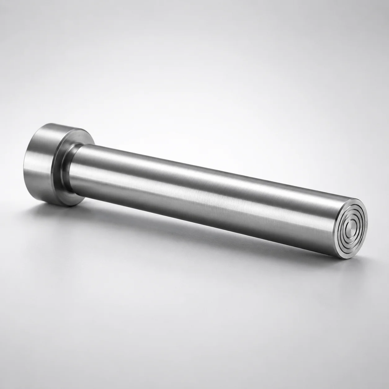
Gas Release Straight Core Pins (M2 steel) use a flat-sided anti-rotation head and a gas-release profile to support reliable mold venting and consistent positioning during production. The hardened steel construction is built for repeatable core pin performance under load.
- Gas-release design with flat-sided head for stable anti-rotation positioning
- Quenched hardening steel (M2) enhances wear resistance in core operations
- Supports tight L dimension tolerances (+0.01/0 or +0.02/0) for precise fit
- Used in precision injection molds requiring controlled venting through core pins
Specifications
189 configurations available
| Shaft diameter tolerance | L dimension tolerance | D/P (Shaft diameter) (mm) | Gas release shape | No. (Nominal diameter) (mm) | L (L dimension) (mm) | E (Facet cutting depth) (mm) | type |
|---|---|---|---|---|---|---|---|
| 0/-0.005 | +0.02/0 | 0.5 | Single flat cutting | - | 15 ~ 60 | 0.02 ~ 0.05 | - |
| 0/-0.005 | +0.02/0 | 0.6 | Single flat cutting | - | 15 ~ 100 | 0.02 ~ 0.05 | - |
| 0/-0.005 | +0.02/0 | 0.7 | Single flat cutting | - | 15 ~ 100 | 0.02 ~ 0.05 | - |
| 0/-0.005 | +0.02/0 | 0.8 | Single flat cutting | - | 15 ~ 100 | 0.02 ~ 0.05 | - |
| 0/-0.005 | +0.02/0 | 0.9 | Single flat cutting | - | 15 ~ 100 | 0.02 ~ 0.05 | - |
| 0/-0.005 | +0.02/0 | 1 | Single flat cutting | - | 15 ~ 100 | 0.02 ~ 0.05 | - |
| 0/-0.005 | +0.02/0 | 1.2 | Single flat cutting | - | 15 ~ 100 | 0.02 ~ 0.05 | - |
| 0/-0.005 | +0.02/0 | 1.5 | Single flat cutting | - | 15 ~ 100 | 0.02 ~ 0.05 | - |
| 0/-0.005 | +0.02/0 | 2 | Single flat cutting | - | 15 ~ 100 | 0.02 ~ 0.05 | - |
| 0/-0.005 | +0.02/0 | 2.5 | Single flat cutting | - | 15 ~ 100 | 0.02 ~ 0.05 | - |
| 0/-0.005 | +0.02/0 | 3 | Single flat cutting | - | 15 ~ 100 | 0.02 ~ 0.05 | - |
| 0/-0.005 | +0.02/0 | 3.5 | Single flat cutting | - | 15 ~ 120 | 0.02 ~ 0.05 | - |
| 0/-0.005 | +0.02/0 | 4 | Single flat cutting | - | 15 ~ 120 | 0.02 ~ 0.05 | - |
| 0/-0.005 | +0.02/0 | 4.5 | Single flat cutting | - | 15 ~ 120 | 0.02 ~ 0.05 | - |
| 0/-0.005 | +0.02/0 | 5 | Single flat cutting | - | 15 ~ 120 | 0.02 ~ 0.05 | - |
| 0/-0.005 | +0.02/0 | 6 | Single flat cutting | - | 15 ~ 120 | 0.02 ~ 0.05 | - |
| 0/-0.005 | +0.02/0 | 7 | Single flat cutting | - | 15 ~ 120 | 0.02 ~ 0.05 | - |
| 0/-0.005 | +0.02/0 | 8 | Single flat cutting | - | 15 ~ 120 | 0.02 ~ 0.05 | - |
| 0/-0.005 | +0.02/0 | 10 | Single flat cutting | - | 15 ~ 120 | 0.02 ~ 0.05 | - |
| 0/-0.005 | +0.02/0 | 13 | Single flat cutting | - | 15 ~ 120 | 0.02 ~ 0.05 | - |
| 0/-0.005 | +0.02/0 | 0.5 ~ 0.59 | Single flat cutting | 0.6 | 15 ~ 100 | 0.02 ~ 0.05 | - |
| 0/-0.005 | +0.02/0 | 0.6 ~ 0.99 | Single flat cutting | 1 | 15 ~ 100 | 0.02 ~ 0.05 | - |
| 0/-0.005 | +0.02/0 | 1 ~ 1.49 | Single flat cutting | 1.5 | 15 ~ 100 | 0.02 ~ 0.05 | - |
| 0/-0.005 | +0.02/0 | 1.5 ~ 1.99 | Single flat cutting | 2 | 15 ~ 100 | 0.02 ~ 0.05 | - |
| 0/-0.005 | +0.02/0 | 2 ~ 2.49 | Single flat cutting | 2.5 | 15 ~ 100 | 0.02 ~ 0.05 | - |
| 0/-0.005 | +0.02/0 | 2.5 ~ 2.99 | Single flat cutting | 3 | 15 ~ 100 | 0.02 ~ 0.05 | - |
| 0/-0.005 | +0.02/0 | 3 ~ 3.49 | Single flat cutting | 3.5 | 15 ~ 120 | 0.02 ~ 0.05 | - |
| 0/-0.005 | +0.02/0 | 3.5 ~ 3.99 | Single flat cutting | 4 | 15 ~ 120 | 0.02 ~ 0.05 | - |
| 0/-0.005 | +0.02/0 | 4 ~ 4.49 | Single flat cutting | 4.5 | 15 ~ 120 | 0.02 ~ 0.05 | - |
| 0/-0.005 | +0.02/0 | 4.5 ~ 4.99 | Single flat cutting | 5 | 15 ~ 120 | 0.02 ~ 0.05 | - |
| 0/-0.005 | +0.02/0 | 5.5 ~ 5.99 | Single flat cutting | 6 | 15 ~ 120 | 0.02 ~ 0.05 | - |
| 0/-0.005 | +0.02/0 | 6.5 ~ 6.99 | Single flat cutting | 7 | 15 ~ 120 | 0.02 ~ 0.05 | - |
| 0/-0.005 | +0.02/0 | 7 ~ 7.99 | Single flat cutting | 8 | 15 ~ 120 | 0.02 ~ 0.05 | - |
| 0/-0.005 | +0.02/0 | 8 ~ 9.99 | Single flat cutting | 10 | 15 ~ 120 | 0.02 ~ 0.05 | - |
| 0/-0.005 | +0.02/0 | 10 ~ 12.99 | Single flat cutting | 13 | 15 ~ 120 | 0.02 ~ 0.05 | - |
| 0/-0.005 | +0.01/0 | 0.5 | Single flat cutting | - | 15 ~ 60 | 0.02 ~ 0.05 | - |
| 0/-0.005 | +0.01/0 | 0.6 | Single flat cutting | - | 15 ~ 100 | 0.02 ~ 0.05 | - |
| 0/-0.005 | +0.01/0 | 0.7 | Single flat cutting | - | 15 ~ 100 | 0.02 ~ 0.05 | - |
| 0/-0.005 | +0.01/0 | 0.8 | Single flat cutting | - | 15 ~ 100 | 0.02 ~ 0.05 | - |
| 0/-0.005 | +0.01/0 | 0.9 | Single flat cutting | - | 15 ~ 100 | 0.02 ~ 0.05 | - |
| 0/-0.005 | +0.01/0 | 1 | Single flat cutting | - | 15 ~ 100 | 0.02 ~ 0.05 | - |
| 0/-0.005 | +0.01/0 | 1.2 | Single flat cutting | - | 15 ~ 100 | 0.02 ~ 0.05 | - |
| 0/-0.005 | +0.01/0 | 1.5 | Single flat cutting | - | 15 ~ 100 | 0.02 ~ 0.05 | - |
| 0/-0.005 | +0.01/0 | 2 | Single flat cutting | - | 15 ~ 100 | 0.02 ~ 0.05 | - |
| 0/-0.005 | +0.01/0 | 2.5 | Single flat cutting | - | 15 ~ 100 | 0.02 ~ 0.05 | - |
| 0/-0.005 | +0.01/0 | 3 | Single flat cutting | - | 15 ~ 100 | 0.02 ~ 0.05 | - |
| 0/-0.005 | +0.01/0 | 3.5 | Single flat cutting | - | 15 ~ 120 | 0.02 ~ 0.05 | - |
| 0/-0.005 | +0.01/0 | 4 | Single flat cutting | - | 15 ~ 120 | 0.02 ~ 0.05 | - |
| 0/-0.005 | +0.01/0 | 4.5 | Single flat cutting | - | 15 ~ 120 | 0.02 ~ 0.05 | - |
| 0/-0.005 | +0.01/0 | 5 | Single flat cutting | - | 15 ~ 120 | 0.02 ~ 0.05 | - |
Product Guide
Application Scenarios+
These flat-sided gas release core pins are used in injection mold tooling where controlled venting is needed through the core pin itself while maintaining exact core alignment. The flat-sided anti-rotation head helps prevent unwanted pin rotation during repeated closure cycles, supporting consistent vent path performance.
Common scenarios include automotive connector and housing molds, where trapped air behind thin ribs can cause splay or burn marks. The gas-release profile (single flat cutting or four flats cutting) improves venting effectiveness while the quenched M2 hardening steel improves dimensional stability under core-pin load.
They are also suitable for consumer and appliance components with fine surface features, where vent consistency affects surface finish. For multi-cavity molds that require predictable part-to-part alignment, the specified L dimension tolerances (+0.02/0 or +0.01/0) support accurate engagement and repeatable core seating.
- Flat-sided head for stable anti-rotation positioning
- Gas-release cutting geometry for reliable venting
- Quenched hardening steel durability for long production runs
Material & Process Details+
The core pins are specified in M2 steel, a quenched hardening steel commonly selected for mold core components requiring strong wear resistance. After machining, they are manufactured with a quench-hardening heat treatment to achieve a hard, wear-resistant surface suitable for sliding and contact conditions around the core pin.
In service, the quenched condition improves wear resistance for repeated venting and loading, but it typically reduces impact toughness versus lower-alloy or softer conditions. Proper design of pin diameter and vent geometry helps manage stress concentrations at the cutting edges.
- Heat treatment state: quenched hardening steel (M2)
- Hardness: hardness target is not provided in the input data (select heat-treatment to meet your wear/toughness requirement)
- Wear vs. toughness trade-off: higher hardness for wear, with careful consideration for brittle-edge risk
If comparing options, you would generally select M2 for higher abrasive/adhesive wear resistance, while alternative steels with different tempering strategies may be chosen when maximum toughness is prioritized; however, only M2 is specified here.
Sizing & Selection Guide+
Selection is driven by matching the pin’s shaft diameter (D/P) and length (L) to the mold’s core support, bushings, and the required vent reach. Choose D/P (Shaft diameter) in the 0.5 ~ 13 mm range and confirm that the corresponding nominal diameter 0.6 ~ 13 mm aligns with your core pin hole specification.
Verify length first: available L dimensions are 15 ~ 60 mm, 15 ~ 100 mm, and 15 ~ 120 mm. The L tolerance is specified as +0.02/0 or +0.01/0, meaning the pin length may be slightly above nominal but not below; therefore, check your stack-up so that the slightly positive tolerance does not interfere with seating depth.
- Shaft diameter tolerance: 0/-0.005 or -0.01/-0.02 (select the fit for your bushing/core-pin bore)
- Facet cutting depth (E): fixed at 0.02 ~ 0.05 mm for the vent geometry
- Gas release shape: choose single flat cutting or four flats cutting based on venting demand
Finally, ensure the flat-sided anti-rotation head matches your anti-rotation feature geometry so positioning remains stable over the full production cycle.
Frequently Asked Questions
Which shaft diameter range (D/P) and tolerance should I use for these M2 gas release core pins?+
How do I choose the correct L dimension when the pin length tolerance is only positive (+0.01/0 or +0.02/0)?+
What gas release geometry options are available, and how might they affect venting performance?+
Does the flat-sided anti-rotation feature change how I design the pin seating or anti-rotation pocket?+
What heat treatment and material basis does the DIN M2 steel variant provide?+
Related Products
Need Custom Specifications?
Our engineering team can help with custom configurations, material selection, and volume pricing.