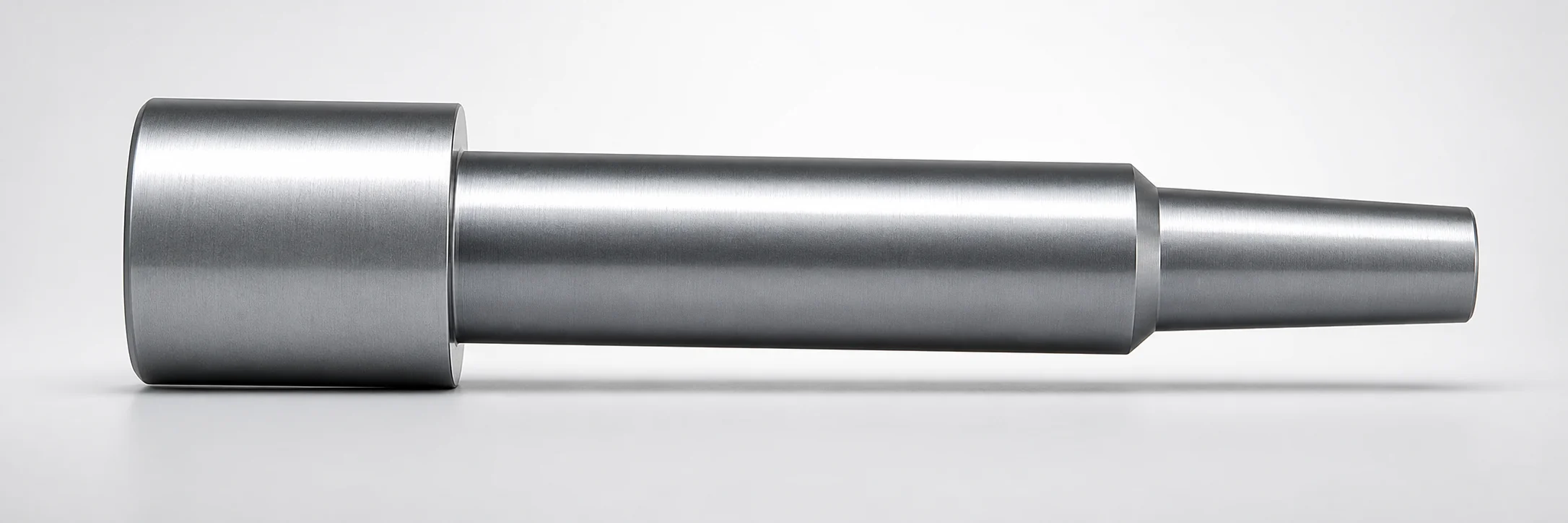
JIS Standard Steel One-Step Core Pins
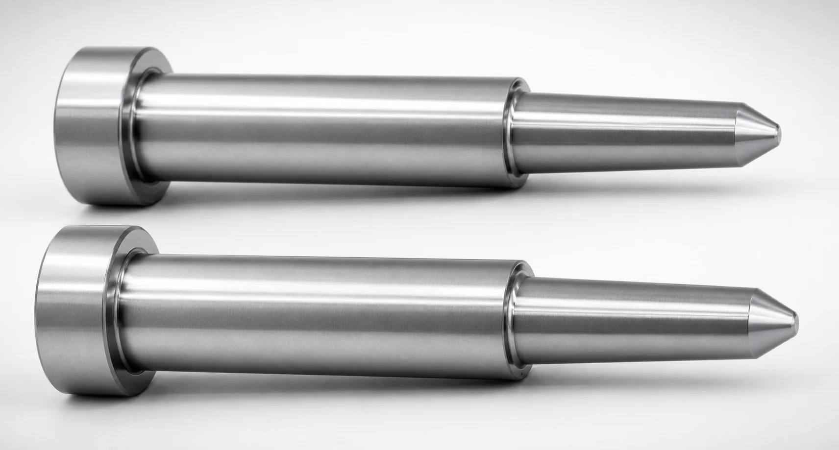
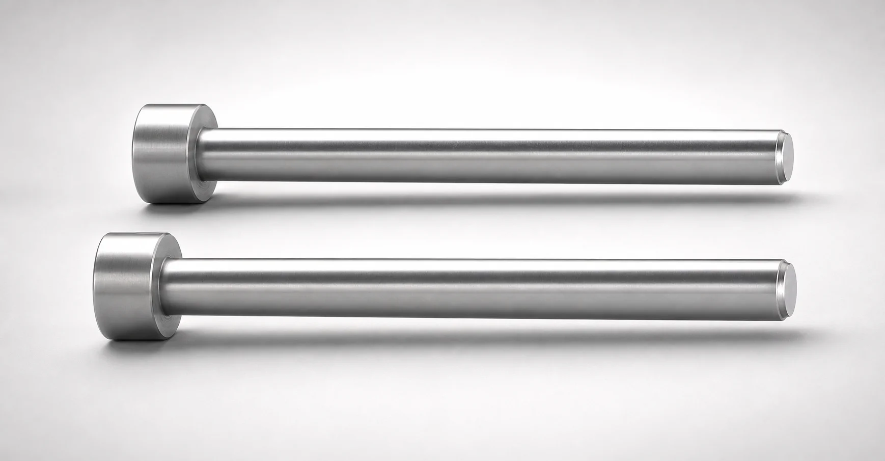
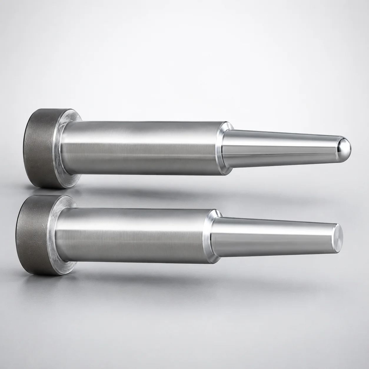
One-step core pins (hardened steel) use a one-step shape for direct locating and ejection support in precision molds, with an optional TiCN coating to improve surface durability. The simplified head and tip design supports consistent assembly performance under production loads.
- One-step geometry with no second step for straightforward positioning and mold alignment
- Hardened SKH51/SKD61 steel construction with optional TiCN coating for wear resistance
- Supports controlled L dimension tolerances (+0.02/0) for repeatable core pin engagement
- Configured for typical die-and-mold core applications where compact locating pins are required
Specifications
1222 configurations available
| Material | Shaft Diameter Tolerance | L Dimension Tolerance | Tip Gradient Tolerance | Surface Treatment | D/P (Shaft Diameter) (mm) | First Step Shape | Tip Shape | No. (Nominal diameter) (mm) | RE (R shape alteration・enlargement) (mm) | A (Step shape diameter) (mm) | C (Step type taper width) (mm) | F (Bearing bore length) (mm) | G (Tip C chamfering width) (mm) | K (Tip angle) (°) | L (L dimension) (mm) | Q (Tip R chamfering) (mm) | R (Step type R) (mm) | S (Tip tapered width) (mm) | T (Head thickness) (mm) | V (Tip diameter) (mm) | type |
|---|---|---|---|---|---|---|---|---|---|---|---|---|---|---|---|---|---|---|---|---|---|
| SKD61 | -0.01/-0.02 | +0.02/0 | ±0.015 | No | 1 ~ 1.5 | 1A | No processing | 3 | - | - | - | 12 ~ 119.5 | - | - | 20 ~ 120 | - | - | - | 1.5 ~ 20 | 0.5 ~ 1.49 | - |
| SKD61 | -0.01/-0.02 | +0.02/0 | ±0.015 | No | 1 ~ 2 | 1A | No processing | 4 | - | - | - | 12 ~ 119.5 | - | - | 20 ~ 120 | - | - | - | 1.5 ~ 20 | 0.7 ~ 1.99 | - |
| SKD61 | -0.01/-0.02 | +0.02/0 | ±0.015 | No | 1.5 ~ 2.5 | 1A | No processing | 5 | - | - | - | 12 ~ 119.5 | - | - | 20 ~ 120 | - | - | - | 1.5 ~ 20 | 0.7 ~ 2.49 | - |
| SKD61 | -0.01/-0.02 | +0.02/0 | ±0.015 | No | 2 ~ 3 | 1A | No processing | 6 | - | - | - | 12 ~ 119.5 | - | - | 20 ~ 120 | - | - | - | 1.5 ~ 20 | 1 ~ 2.99 | - |
| SKD61 | -0.01/-0.02 | +0.02/0 | ±0.015 | No | 2.5 ~ 3.5 | 1A | No processing | 7 | - | - | - | 12 ~ 119.5 | - | - | 20 ~ 120 | - | - | - | 1.5 ~ 20 | 1 ~ 3.49 | - |
| SKD61 | -0.01/-0.02 | +0.02/0 | ±0.015 | No | 3.5 ~ 5 | 1A | No processing | 8 | - | - | - | 12 ~ 119.5 | - | - | 20 ~ 120 | - | - | - | 1.5 ~ 20 | 1.5 ~ 4.99 | - |
| SKD61 | -0.01/-0.02 | +0.02/0 | ±0.015 | No | 4.5 ~ 6 | 1A | No processing | 9 | - | - | - | 12 ~ 119.5 | - | - | 20 ~ 120 | - | - | - | 1.5 ~ 20 | 1.5 ~ 5.99 | - |
| SKD61 | -0.01/-0.02 | +0.02/0 | ±0.015 | No | 5.5 ~ 7 | 1A | No processing | 10 | - | - | - | 12 ~ 119.5 | - | - | 20 ~ 120 | - | - | - | 1.5 ~ 20 | 1.5 ~ 6.99 | - |
| SKD61 | -0.01/-0.02 | +0.02/0 | ±0.015 | No | 6.5 ~ 8 | 1A | No processing | 11 | - | - | - | 12 ~ 119.5 | - | - | 20 ~ 120 | - | - | - | 1.5 ~ 20 | 1.5 ~ 7.99 | - |
| SKD61 | -0.01/-0.02 | +0.02/0 | ±0.015 | No | 7.5 ~ 10 | 1A | No processing | 15 | - | - | - | 12 ~ 119.5 | - | - | 20 ~ 120 | - | - | - | 1.5 ~ 20 | 1.5 ~ 9.99 | - |
| SKD61 | -0.01/-0.02 | +0.02/0 | ±0.015 | No | 9.5 ~ 13 | 1A | No processing | 18 | - | - | - | 12 ~ 119.5 | - | - | 20 ~ 120 | - | - | - | 1.5 ~ 20 | 2.5 ~ 12.99 | - |
| SKD61 | -0.01/-0.02 | +0.02/0 | ±0.015 | No | 12.5 ~ 16 | 1A | No processing | 21 | - | - | - | 12 ~ 119.5 | - | - | 20 ~ 120 | - | - | - | 1.5 ~ 20 | 2.5 ~ 15.99 | - |
| SKD61 | -0.01/-0.02 | +0.02/0 | ±0.015 | No | 16.5 ~ 20 | 1A | No processing | 25 | - | - | - | 25.5 ~ 119.5 | - | - | 30 ~ 120 | - | - | - | 1.5 ~ 20 | 5 ~ 19.99 | - |
| SKD61 | -0.01/-0.02 | 0/-0.1 | ±0.015 | No | 1 ~ 1.5 | 1A | B | 3 | - | - | - | 12 ~ 119.25 | - | - | 20 ~ 120 | - | - | - | 1.5 ~ 20 | 0.5 ~ 1.49 | - |
| SKD61 | -0.01/-0.02 | 0/-0.1 | ±0.015 | No | 1 ~ 2 | 1A | B | 4 | - | - | - | 12 ~ 119.15 | - | - | 20 ~ 120 | - | - | - | 1.5 ~ 20 | 0.7 ~ 1.99 | - |
| SKD61 | -0.01/-0.02 | 0/-0.1 | ±0.015 | No | 1.5 ~ 2.5 | 1A | B | 5 | - | - | - | 12 ~ 119.15 | - | - | 20 ~ 120 | - | - | - | 1.5 ~ 20 | 0.7 ~ 2.49 | - |
| SKD61 | -0.01/-0.02 | 0/-0.1 | ±0.015 | No | 2 ~ 3 | 1A | B | 6 | - | - | - | 12 ~ 119 | - | - | 20 ~ 120 | - | - | - | 1.5 ~ 20 | 1 ~ 2.99 | - |
| SKD61 | -0.01/-0.02 | 0/-0.1 | ±0.015 | No | 2.5 ~ 3.5 | 1A | B | 7 | - | - | - | 12 ~ 119 | - | - | 20 ~ 120 | - | - | - | 1.5 ~ 20 | 1 ~ 3.49 | - |
| SKD61 | -0.01/-0.02 | 0/-0.1 | ±0.015 | No | 3.5 ~ 5 | 1A | B | 8 | - | - | - | 12 ~ 118.75 | - | - | 20 ~ 120 | - | - | - | 1.5 ~ 20 | 1.5 ~ 4.99 | - |
| SKD61 | -0.01/-0.02 | 0/-0.1 | ±0.015 | No | 4.5 ~ 6 | 1A | B | 9 | - | - | - | 12 ~ 118.75 | - | - | 20 ~ 120 | - | - | - | 1.5 ~ 20 | 1.5 ~ 5.99 | - |
| SKD61 | -0.01/-0.02 | 0/-0.1 | ±0.015 | No | 5.5 ~ 7 | 1A | B | 10 | - | - | - | 12 ~ 118.75 | - | - | 20 ~ 120 | - | - | - | 1.5 ~ 20 | 1.5 ~ 6.99 | - |
| SKD61 | -0.01/-0.02 | 0/-0.1 | ±0.015 | No | 6.5 ~ 8 | 1A | B | 11 | - | - | - | 12 ~ 118.75 | - | - | 20 ~ 120 | - | - | - | 1.5 ~ 20 | 1.5 ~ 7.99 | - |
| SKD61 | -0.01/-0.02 | 0/-0.1 | ±0.015 | No | 7.5 ~ 10 | 1A | B | 15 | - | - | - | 12 ~ 118.75 | - | - | 20 ~ 120 | - | - | - | 1.5 ~ 20 | 1.5 ~ 9.99 | - |
| SKD61 | -0.01/-0.02 | 0/-0.1 | ±0.015 | No | 9.5 ~ 13 | 1A | B | 18 | - | - | - | 12 ~ 118.25 | - | - | 20 ~ 120 | - | - | - | 1.5 ~ 20 | 2.5 ~ 12.99 | - |
| SKD61 | -0.01/-0.02 | 0/-0.1 | ±0.015 | No | 12.5 ~ 16 | 1A | B | 21 | - | - | - | 12 ~ 118.25 | - | - | 20 ~ 120 | - | - | - | 1.5 ~ 20 | 2.5 ~ 15.99 | - |
| SKD61 | -0.01/-0.02 | 0/-0.1 | ±0.015 | No | 16.5 ~ 20 | 1A | B | 25 | - | - | - | 25.5 ~ 119.5 | - | - | 20 ~ 120 | - | - | - | 1.5 ~ 20 | 5 ~ 19.99 | - |
| SKD61 | -0.01/-0.02 | +0.02/0 | ±0.015 | No | 1 ~ 1.5 | 1A | C | 3 | - | - | - | 12 ~ 119 | 0.5 ~ 0.7 | - | 20 ~ 120 | - | - | - | 1.5 ~ 20 | 0.5 ~ 1.49 | - |
| SKD61 | -0.01/-0.02 | +0.02/0 | ±0.015 | No | 1 ~ 2 | 1A | C | 4 | - | - | - | 12 ~ 119 | 0.5 ~ 0.9 | - | 20 ~ 120 | - | - | - | 1.5 ~ 20 | 0.7 ~ 1.99 | - |
| SKD61 | -0.01/-0.02 | +0.02/0 | ±0.015 | No | 1.5 ~ 2.5 | 1A | C | 5 | - | - | - | 12 ~ 119 | 0.5 ~ 1.2 | - | 20 ~ 120 | - | - | - | 1.5 ~ 20 | 0.7 ~ 2.49 | - |
| SKD61 | -0.01/-0.02 | +0.02/0 | ±0.015 | No | 2 ~ 3 | 1A | C | 6 | - | - | - | 12 ~ 119 | 0.5 ~ 1.4 | - | 20 ~ 120 | - | - | - | 1.5 ~ 20 | 1 ~ 2.99 | - |
| SKD61 | -0.01/-0.02 | +0.02/0 | ±0.015 | No | 2.5 ~ 3.5 | 1A | C | 7 | - | - | - | 12 ~ 119 | 0.5 ~ 1.7 | - | 20 ~ 120 | - | - | - | 1.5 ~ 20 | 1 ~ 3.49 | - |
| SKD61 | -0.01/-0.02 | +0.02/0 | ±0.015 | No | 3.5 ~ 5 | 1A | C | 8 | - | - | - | 12 ~ 119 | 0.5 ~ 2.4 | - | 20 ~ 120 | - | - | - | 1.5 ~ 20 | 1.5 ~ 4.99 | - |
| SKD61 | -0.01/-0.02 | +0.02/0 | ±0.015 | No | 4.5 ~ 6 | 1A | C | 9 | - | - | - | 12 ~ 119 | 0.5 ~ 2.9 | - | 20 ~ 120 | - | - | - | 1.5 ~ 20 | 1.5 ~ 5.99 | - |
| SKD61 | -0.01/-0.02 | +0.02/0 | ±0.015 | No | 5.5 ~ 7 | 1A | C | 10 | - | - | - | 12 ~ 119 | 0.5 ~ 3.4 | - | 20 ~ 120 | - | - | - | 1.5 ~ 20 | 1.5 ~ 6.99 | - |
| SKD61 | -0.01/-0.02 | +0.02/0 | ±0.015 | No | 6.5 ~ 8 | 1A | C | 11 | - | - | - | 12 ~ 119 | 0.5 ~ 3.9 | - | 20 ~ 120 | - | - | - | 1.5 ~ 20 | 1.5 ~ 7.99 | - |
| SKD61 | -0.01/-0.02 | +0.02/0 | ±0.015 | No | 7.5 ~ 10 | 1A | C | 15 | - | - | - | 12 ~ 119 | 0.5 ~ 4.9 | - | 20 ~ 120 | - | - | - | 1.5 ~ 20 | 1.5 ~ 9.99 | - |
| SKD61 | -0.01/-0.02 | +0.02/0 | ±0.015 | No | 9.5 ~ 13 | 1A | C | 18 | - | - | - | 12 ~ 119 | 0.5 ~ 6.4 | - | 20 ~ 120 | - | - | - | 1.5 ~ 20 | 2.5 ~ 12.99 | - |
| SKD61 | -0.01/-0.02 | +0.02/0 | ±0.015 | No | 12.5 ~ 16 | 1A | C | 21 | - | - | - | 12 ~ 119 | 0.5 ~ 7.9 | - | 20 ~ 120 | - | - | - | 1.5 ~ 20 | 2.5 ~ 15.99 | - |
| SKD61 | -0.01/-0.02 | +0.02/0 | ±0.015 | No | 16.5 ~ 20 | 1A | C | 25 | - | - | - | 25.5 ~ 119.5 | 0.5 ~ 7.9 | - | 20 ~ 120 | - | - | - | 1.5 ~ 20 | 5 ~ 19.99 | - |
| SKD61 | -0.01/-0.02 | 0/-0.1 | ±0.015 | No | 1 ~ 1.5 | 1A | G | 3 | - | - | - | 12 ~ 119 | - | 21 ~ 60 | 20 ~ 120 | - | - | - | 1.5 ~ 20 | 0.5 ~ 1.49 | - |
| SKD61 | -0.01/-0.02 | 0/-0.1 | ±0.015 | No | 1 ~ 2 | 1A | G | 4 | - | - | - | 12 ~ 119 | - | 21 ~ 60 | 20 ~ 120 | - | - | - | 1.5 ~ 20 | 0.7 ~ 1.99 | - |
| SKD61 | -0.01/-0.02 | 0/-0.1 | ±0.015 | No | 1.5 ~ 2.5 | 1A | G | 5 | - | - | - | 12 ~ 119 | - | 21 ~ 60 | 20 ~ 120 | - | - | - | 1.5 ~ 20 | 0.7 ~ 2.49 | - |
| SKD61 | -0.01/-0.02 | 0/-0.1 | ±0.015 | No | 2 ~ 3 | 1A | G | 6 | - | - | - | 12 ~ 119 | - | 21 ~ 60 | 20 ~ 120 | - | - | - | 1.5 ~ 20 | 1 ~ 2.99 | - |
| SKD61 | -0.01/-0.02 | 0/-0.1 | ±0.015 | No | 2.5 ~ 3.5 | 1A | G | 7 | - | - | - | 12 ~ 119 | - | 21 ~ 60 | 20 ~ 120 | - | - | - | 1.5 ~ 20 | 1 ~ 3.49 | - |
| SKD61 | -0.01/-0.02 | 0/-0.1 | ±0.015 | No | 3.5 ~ 5 | 1A | G | 8 | - | - | - | 12 ~ 119 | - | 21 ~ 60 | 20 ~ 120 | - | - | - | 1.5 ~ 20 | 1.5 ~ 4.99 | - |
| SKD61 | -0.01/-0.02 | 0/-0.1 | ±0.015 | No | 4.5 ~ 6 | 1A | G | 9 | - | - | - | 12 ~ 119 | - | 21 ~ 60 | 20 ~ 120 | - | - | - | 1.5 ~ 20 | 1.5 ~ 5.99 | - |
| SKD61 | -0.01/-0.02 | 0/-0.1 | ±0.015 | No | 5.5 ~ 7 | 1A | G | 10 | - | - | - | 12 ~ 119 | - | 21 ~ 60 | 20 ~ 120 | - | - | - | 1.5 ~ 20 | 1.5 ~ 6.99 | - |
| SKD61 | -0.01/-0.02 | 0/-0.1 | ±0.015 | No | 6.5 ~ 8 | 1A | G | 11 | - | - | - | 12 ~ 119 | - | 21 ~ 60 | 20 ~ 120 | - | - | - | 1.5 ~ 20 | 1.5 ~ 7.99 | - |
| SKD61 | -0.01/-0.02 | 0/-0.1 | ±0.015 | No | 7.5 ~ 10 | 1A | G | 15 | - | - | - | 12 ~ 119 | - | 21 ~ 60 | 20 ~ 120 | - | - | - | 1.5 ~ 20 | 1.5 ~ 9.99 | - |
| SKD61 | -0.01/-0.02 | 0/-0.1 | ±0.015 | No | 9.5 ~ 13 | 1A | G | 18 | - | - | - | 12 ~ 119 | - | 21 ~ 60 | 20 ~ 120 | - | - | - | 1.5 ~ 20 | 2.5 ~ 12.99 | - |
Product Guide
Application Scenarios+
One-step core pins are used in precision injection mold tooling where the core must be located and supported through a single, direct engagement feature—without a second locating step. This makes the pin effective for compact core systems that require repeatable alignment during closing, ejection support, and long production runs.
- Automotive connector and insert molding: Use in multi-cavity tooling to stabilize core positioning while the hardened steel resists wear at the contact surface. The optional TiCN coating improves surface durability under frequent cycles.
- Consumer electronics housings: Suitable for stepped round cores that need consistent ejection support and reduced assembly variance. The selectable shaft diameter tolerances (e.g., 1–16.5 mm D/P) help match tighter fit requirements.
- Medical device component cores: Helps maintain dimensional stability in molds with smaller, high-precision locating areas. Use the pin variant with controlled L dimension tolerance (+0.02/0) when core engagement length is critical.
Material & Process Details+
These one-step core pins are made from SKD61 or SKH51 hardened steel, selected to balance wear resistance and toughness for mold core locating applications. SKD61 is commonly specified for hot-work die steels (often treated to achieve high hardness), while SKH51 is a high-speed steel variant (often used when abrasion resistance at the contact zone is critical).
- Surface treatment: Available as No treatment or with TiCN coating, which increases surface hardness and improves wear resistance under repetitive contact.
- Hardness & trade-offs: Higher hardness improves wear life, but can reduce toughness if not properly heat treated; selecting SKD61 vs. SKH51 supports the required performance balance for the core’s duty cycle.
- Heat treatment state: Pins are provided as hardened steel, intended for stable fit after machining and assembly.
Note: Specific HRC values are not provided in the supplied data.
Sizing & Selection Guide+
To select the correct stepped one-step core pin, match both the shaft diameter and the engagement length (L) to your core/core-cavity locating geometry. The available D/P (shaft diameter) range is 1 ~ 16.5 mm (and nominal diameter 3 ~ 25 mm, depending on configuration), so choose the diameter that fits the mating bore in your mold.
- Engagement length: Select the L dimension from 20 ~ 120 mm (or 30 ~ 120 mm in certain ranges). Use the tolerance option +0.02/0 when you need precise core pin engagement without clearance growth.
- Fit and tolerance: Shaft diameter tolerances are available as -0.01/-0.02 or 0/-0.005. Use the tighter negative tolerance when you require consistent clearance, and the near-zero option when you need close fit stability.
- Geometry compatibility: Choose the first step shape (1A~1E) and the tip shape (No processing, B, C, G, R, T) that match your core lead-in and ejection support requirements.
Confirm the fixed RE (0.5 ~ 2 mm) and K (21 ~ 60°) values align with the stepped profile in your mold drawing.
Frequently Asked Questions
Which D/P (shaft diameter) tolerance option should I use for stable core pin fit?+
How do I choose the L dimension and its tolerance (+0.02/0) for core engagement?+
Is TiCN coating required for wear resistance, or is uncoated hardened steel sufficient?+
What tip geometries are available and how do they affect alignment and insertion?+
How do I select the step shape (1A–1E) and step dimensions (A, RE) for a one-step core design?+
Related Products
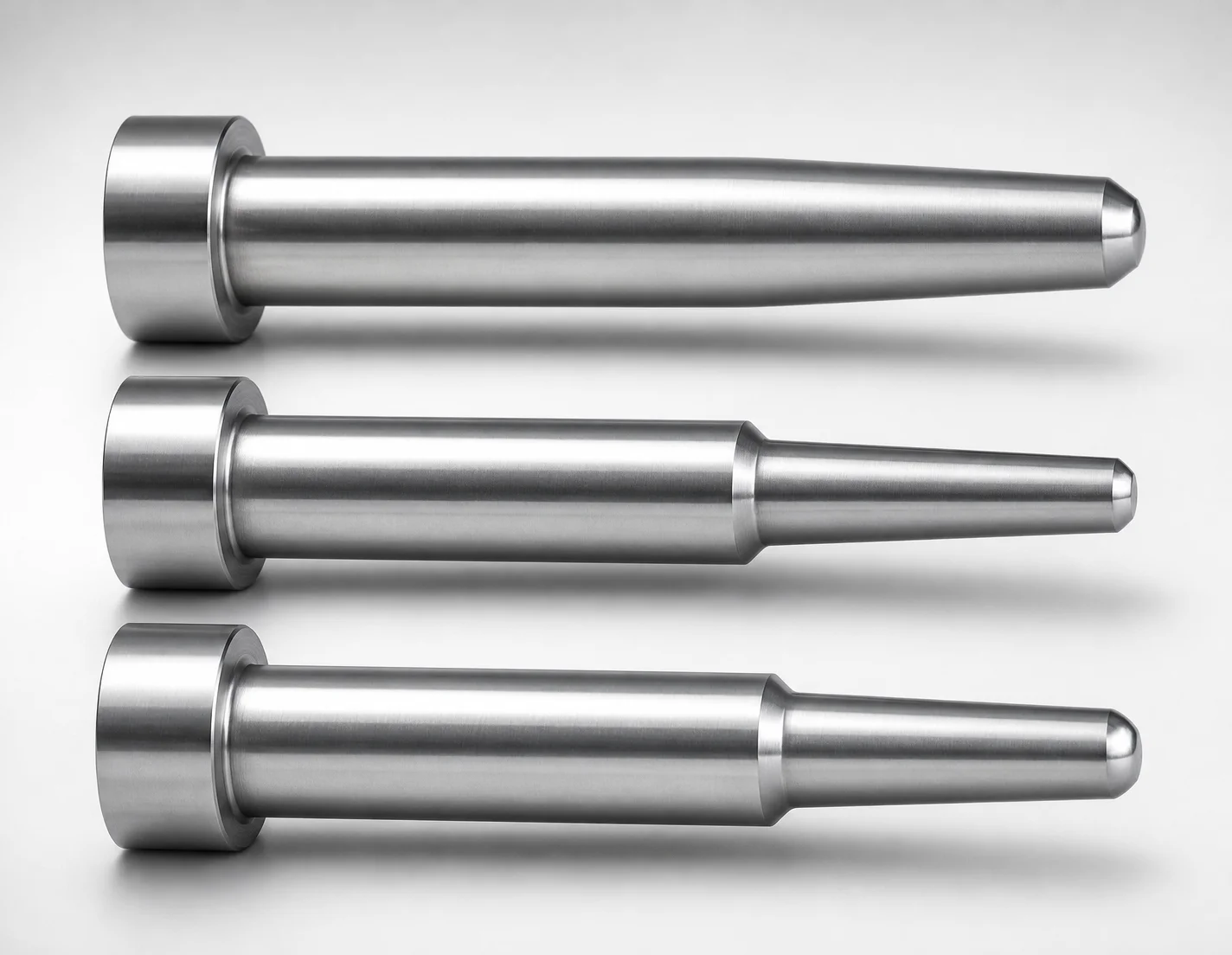
JIS Standard SKH51 Steel One-Step Core Pins - No Second Step
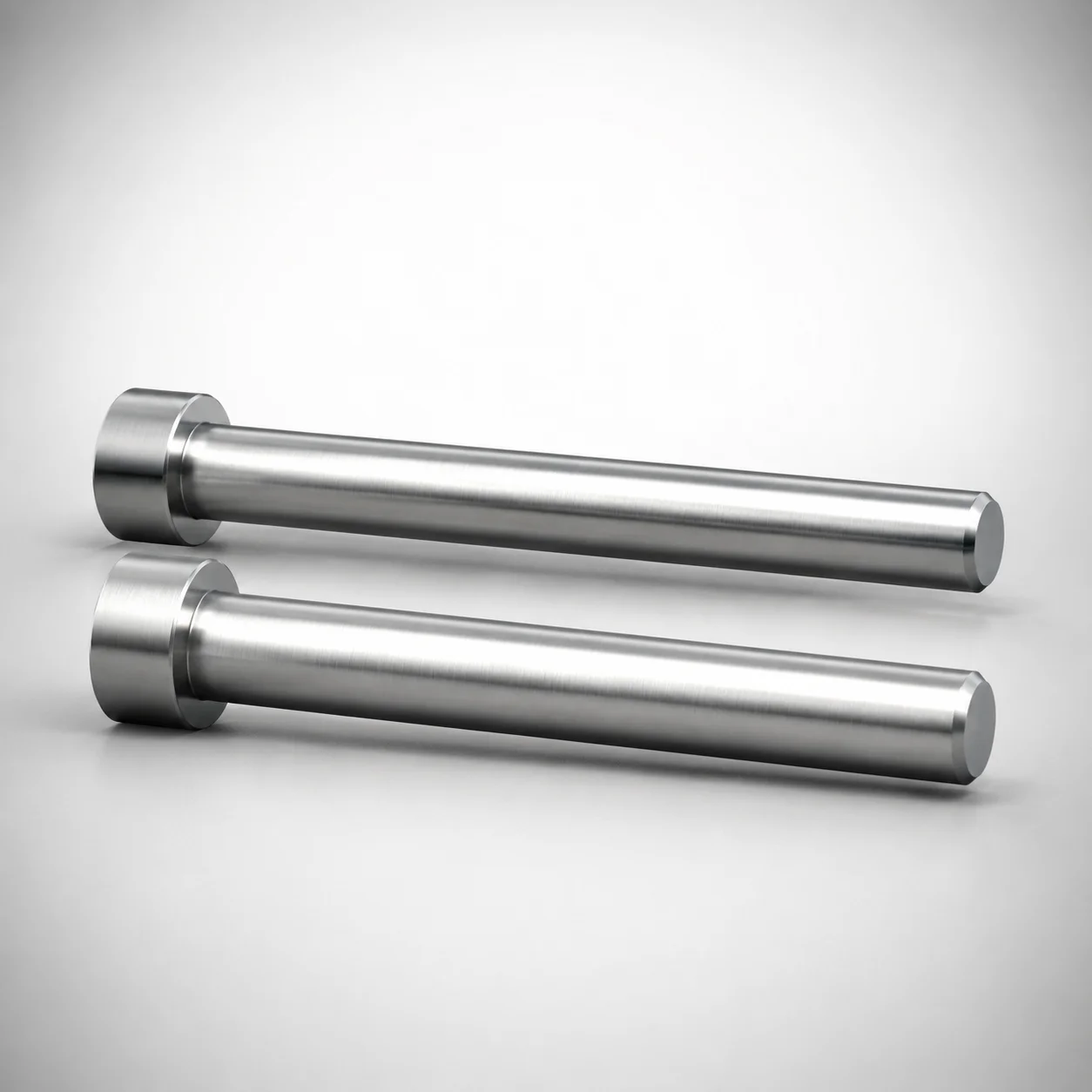
SKH51 Steel Precision Tip Short One-Step Core Pins
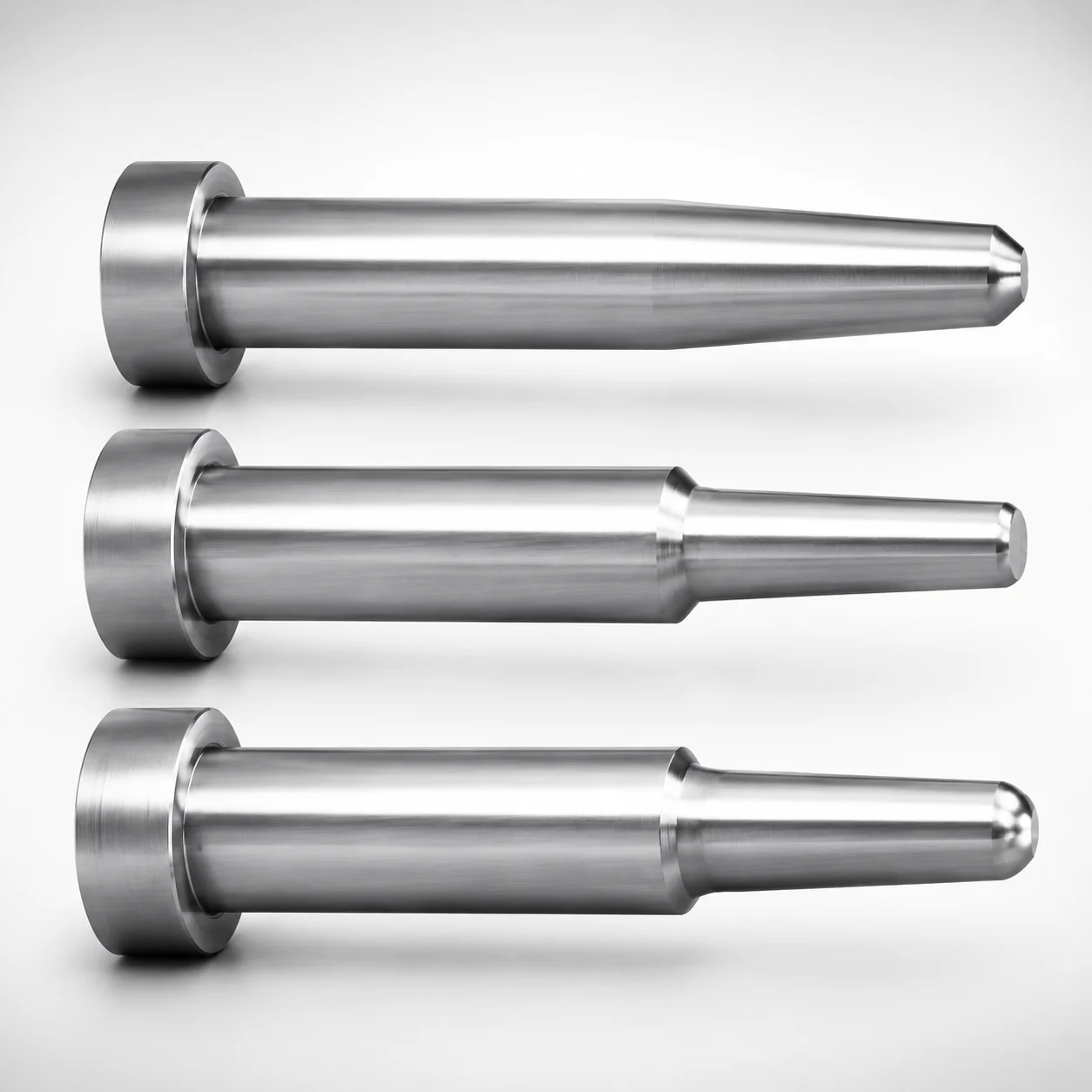
JIS Standard Precision One-Step Core Pins T4 Head
JIS Standard Precision One-Step Core Pins No Second Step
JIS Standard Precision Tip Short One-Step Core Pins
JIS Standard Steel One-Step Core Pins - Tip Lapped
Need Custom Specifications?
Our engineering team can help with custom configurations, material selection, and volume pricing.