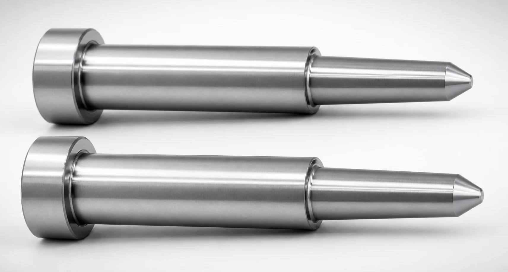
JIS Standard Precision One-Step Core Pins No Second Step
Precision One-Step core pins (SKH51 or SKD61 steel) use a one-step geometry with no second step, helping maintain consistent alignment in core and cavity support assemblies. The precision ground profile supports reliable press-fit and repeatable positioning.
- One-step geometry with no second step for stable core support alignment
- SKH51/SKD61 hardened steel construction for wear-resistant long service life
- Controls shaft fit with 0/-0.005 shaft diameter tolerance and tight tip finish
- Suitable for precision tooling applications where repeatable ejection guidance matters
Specifications
5128 configurations available
| Material | L Dimension Tolerance | D/P (Shaft Diameter) (mm) | First Step Shape | Tip Shape | No. (Nominal diameter) (mm) | A (Step shape diameter) (mm) | C (Step type taper width) (mm) | CVC (Designation of C dimension in increments of 0.01mm) (mm) | F (Bearing bore length) (mm) | FC (Makes F dimension shorter than F min) (mm) | G (Tip C chamfering width) (mm) | K (Tip angle) (°) | L (L dimension) (mm) | Q (Tip R chamfering) (mm) | R (Step type R) (mm) | S (Tip tapered width) (mm) | V (Tip diameter) (mm) | VC (V dimension alteration, smaller than V min) (mm) | type |
|---|---|---|---|---|---|---|---|---|---|---|---|---|---|---|---|---|---|---|---|
| SKH51 | +0.01/0 | 0.8 ~ 0.99 | 1A | No processing | 1 | - | - | - | 10 ~ 99.5 | - | - | - | 6.5 ~ 100 | - | - | - | 0.5 ~ 0.98 | - | - |
| SKH51 | +0.01/0 | 0.8 ~ 0.99 | 1A | No processing | 1 | - | - | - | 10 ~ 99.5 | - | - | - | 6.5 ~ 100 | - | - | - | - | 0.4 ~ 0.49 | - |
| SKH51 | +0.01/0 | 0.8 ~ 0.99 | 1A | No processing | 1 | - | - | - | - | 5 ~ 11.99 | - | - | 6.5 ~ 100 | - | - | - | 0.5 ~ 0.98 | - | - |
| SKH51 | +0.01/0 | 0.8 ~ 0.99 | 1A | No processing | 1 | - | - | - | - | 5 ~ 11.99 | - | - | 6.5 ~ 100 | - | - | - | - | 0.4 ~ 0.49 | - |
| SKH51 | +0.01/0 | 1 ~ 1.495 | 1A | No processing | 1.5 | - | - | - | 12 ~ 119.5 | - | - | - | 6.5 ~ 100 | - | - | - | 0.5 ~ 1.48 | - | - |
| SKH51 | +0.01/0 | 1 ~ 1.495 | 1A | No processing | 1.5 | - | - | - | 12 ~ 119.5 | - | - | - | 6.5 ~ 100 | - | - | - | - | 0.4 ~ 0.49 | - |
| SKH51 | +0.01/0 | 1 ~ 1.495 | 1A | No processing | 1.5 | - | - | - | - | 5 ~ 11.99 | - | - | 6.5 ~ 100 | - | - | - | 0.5 ~ 1.48 | - | - |
| SKH51 | +0.01/0 | 1 ~ 1.495 | 1A | No processing | 1.5 | - | - | - | - | 5 ~ 11.99 | - | - | 6.5 ~ 100 | - | - | - | - | 0.4 ~ 0.49 | - |
| SKH51 | +0.01/0 | 1.5 ~ 1.99 | 1A | No processing | 2 | - | - | - | 12 ~ 99.5 | - | - | - | 6.5 ~ 100 | - | - | - | 0.5 ~ 1.99 | - | - |
| SKH51 | +0.01/0 | 1.5 ~ 1.99 | 1A | No processing | 2 | - | - | - | 12 ~ 99.5 | - | - | - | 6.5 ~ 100 | - | - | - | - | 0.5 ~ 0.69 | - |
| SKH51 | +0.01/0 | 1.5 ~ 1.99 | 1A | No processing | 2 | - | - | - | - | 5 ~ 11.99 | - | - | 6.5 ~ 100 | - | - | - | 0.5 ~ 1.99 | - | - |
| SKH51 | +0.01/0 | 1.5 ~ 1.99 | 1A | No processing | 2 | - | - | - | - | 5 ~ 11.99 | - | - | 6.5 ~ 100 | - | - | - | - | 0.5 ~ 0.69 | - |
| SKH51 | +0.01/0 | 2 ~ 2.495 | 1A | No processing | 2.5 | - | - | - | 12 ~ 99.5 | - | - | - | 6.5 ~ 100 | - | - | - | 0.5 ~ 2.49 | - | - |
| SKH51 | +0.01/0 | 2 ~ 2.495 | 1A | No processing | 2.5 | - | - | - | 12 ~ 99.5 | - | - | - | 6.5 ~ 100 | - | - | - | - | 0.5 ~ 0.69 | - |
| SKH51 | +0.01/0 | 2 ~ 2.495 | 1A | No processing | 2.5 | - | - | - | - | 5 ~ 11.99 | - | - | 6.5 ~ 100 | - | - | - | 0.5 ~ 2.49 | - | - |
| SKH51 | +0.01/0 | 2 ~ 2.495 | 1A | No processing | 2.5 | - | - | - | - | 5 ~ 11.99 | - | - | 6.5 ~ 100 | - | - | - | - | 0.5 ~ 0.69 | - |
| SKH51 | +0.01/0 | 2.5 ~ 2.995 | 1A | No processing | 3 | - | - | - | 12 ~ 99.5 | - | - | - | 6.5 ~ 100 | - | - | - | 0.7 ~ 2.99 | - | - |
| SKH51 | +0.01/0 | 2.5 ~ 2.995 | 1A | No processing | 3 | - | - | - | 12 ~ 99.5 | - | - | - | 6.5 ~ 100 | - | - | - | - | 0.7 ~ 0.99 | - |
| SKH51 | +0.01/0 | 2.5 ~ 2.995 | 1A | No processing | 3 | - | - | - | - | 5 ~ 11.99 | - | - | 6.5 ~ 100 | - | - | - | 0.7 ~ 2.99 | - | - |
| SKH51 | +0.01/0 | 2.5 ~ 2.995 | 1A | No processing | 3 | - | - | - | - | 5 ~ 11.99 | - | - | 6.5 ~ 100 | - | - | - | - | 0.7 ~ 0.99 | - |
| SKH51 | +0.01/0 | 3 ~ 3.49 | 1A | No processing | 3.5 | - | - | - | 12 ~ 119.5 | - | - | - | 6.5 ~ 120 | - | - | - | 1 ~ 3.49 | - | - |
| SKH51 | +0.01/0 | 3 ~ 3.49 | 1A | No processing | 3.5 | - | - | - | 12 ~ 119.5 | - | - | - | 6.5 ~ 120 | - | - | - | - | 0.7 ~ 0.99 | - |
| SKH51 | +0.01/0 | 3 ~ 3.49 | 1A | No processing | 3.5 | - | - | - | - | 5 ~ 11.99 | - | - | 6.5 ~ 120 | - | - | - | 1 ~ 3.49 | - | - |
| SKH51 | +0.01/0 | 3 ~ 3.49 | 1A | No processing | 3.5 | - | - | - | - | 5 ~ 11.99 | - | - | 6.5 ~ 120 | - | - | - | - | 0.7 ~ 0.99 | - |
| SKH51 | +0.01/0 | 3.5 ~ 3.99 | 1A | No processing | 4 | - | - | - | 12 ~ 119.5 | - | - | - | 6.5 ~ 120 | - | - | - | 1 ~ 3.99 | - | - |
| SKH51 | +0.01/0 | 3.5 ~ 3.99 | 1A | No processing | 4 | - | - | - | 12 ~ 119.5 | - | - | - | 6.5 ~ 120 | - | - | - | - | 0.7 ~ 0.99 | - |
| SKH51 | +0.01/0 | 3.5 ~ 3.99 | 1A | No processing | 4 | - | - | - | - | 5 ~ 11.99 | - | - | 6.5 ~ 120 | - | - | - | 1 ~ 3.99 | - | - |
| SKH51 | +0.01/0 | 3.5 ~ 3.99 | 1A | No processing | 4 | - | - | - | - | 5 ~ 11.99 | - | - | 6.5 ~ 120 | - | - | - | - | 0.7 ~ 0.99 | - |
| SKH51 | +0.01/0 | 4 ~ 4.495 | 1A | No processing | 4.5 | - | - | - | 12 ~ 119.5 | - | - | - | 6.5 ~ 120 | - | - | - | 1 ~ 4.99 | - | - |
| SKH51 | +0.01/0 | 4 ~ 4.495 | 1A | No processing | 4.5 | - | - | - | 12 ~ 119.5 | - | - | - | 6.5 ~ 120 | - | - | - | - | 1 ~ 1.49 | - |
| SKH51 | +0.01/0 | 4 ~ 4.495 | 1A | No processing | 4.5 | - | - | - | - | 5 ~ 11.99 | - | - | 6.5 ~ 120 | - | - | - | 1 ~ 4.99 | - | - |
| SKH51 | +0.01/0 | 4 ~ 4.495 | 1A | No processing | 4.5 | - | - | - | - | 5 ~ 11.99 | - | - | 6.5 ~ 120 | - | - | - | - | 1 ~ 1.49 | - |
| SKH51 | +0.01/0 | 4.5 ~ 4.995 | 1A | No processing | 5 | - | - | - | 12 ~ 149.99 | - | - | - | 6.5 ~ 150 | - | - | - | 1 ~ 4.99 | - | - |
| SKH51 | +0.01/0 | 4.5 ~ 4.995 | 1A | No processing | 5 | - | - | - | 12 ~ 149.99 | - | - | - | 6.5 ~ 150 | - | - | - | - | 1 ~ 1.49 | - |
| SKH51 | +0.01/0 | 4.5 ~ 4.995 | 1A | No processing | 5 | - | - | - | - | 5 ~ 11.99 | - | - | 6.5 ~ 150 | - | - | - | 1 ~ 4.99 | - | - |
| SKH51 | +0.01/0 | 4.5 ~ 4.995 | 1A | No processing | 5 | - | - | - | - | 5 ~ 11.99 | - | - | 6.5 ~ 150 | - | - | - | - | 1 ~ 1.49 | - |
| SKH51 | +0.01/0 | 5 ~ 5.49 | 1A | No processing | 5.5 | - | - | - | 12 ~ 149.99 | - | - | - | 6.5 ~ 150 | - | - | - | 1.5 ~ 5.49 | - | - |
| SKH51 | +0.01/0 | 5 ~ 5.49 | 1A | No processing | 5.5 | - | - | - | 12 ~ 149.99 | - | - | - | 6.5 ~ 150 | - | - | - | - | 1 ~ 1.49 | - |
| SKH51 | +0.01/0 | 5 ~ 5.49 | 1A | No processing | 5.5 | - | - | - | - | 5 ~ 11.99 | - | - | 6.5 ~ 150 | - | - | - | 1.5 ~ 5.49 | - | - |
| SKH51 | +0.01/0 | 5 ~ 5.49 | 1A | No processing | 5.5 | - | - | - | - | 5 ~ 11.99 | - | - | 6.5 ~ 150 | - | - | - | - | 1 ~ 1.49 | - |
| SKH51 | +0.01/0 | 5.5 ~ 5.99 | 1A | No processing | 6 | - | - | - | 12 ~ 149.99 | - | - | - | 6.5 ~ 150 | - | - | - | 2 ~ 5.99 | - | - |
| SKH51 | +0.01/0 | 5.5 ~ 5.99 | 1A | No processing | 6 | - | - | - | 12 ~ 149.99 | - | - | - | 6.5 ~ 150 | - | - | - | - | 1.5 ~ 1.99 | - |
| SKH51 | +0.01/0 | 5.5 ~ 5.99 | 1A | No processing | 6 | - | - | - | - | 5 ~ 11.99 | - | - | 6.5 ~ 150 | - | - | - | 2 ~ 5.99 | - | - |
| SKH51 | +0.01/0 | 5.5 ~ 5.99 | 1A | No processing | 6 | - | - | - | - | 5 ~ 11.99 | - | - | 6.5 ~ 150 | - | - | - | - | 1.5 ~ 1.99 | - |
| SKH51 | +0.01/0 | 6 ~ 6.495 | 1A | No processing | 6.5 | - | - | - | 12 ~ 149.99 | - | - | - | 6.5 ~ 150 | - | - | - | 2 ~ 6.49 | - | - |
| SKH51 | +0.01/0 | 6 ~ 6.495 | 1A | No processing | 6.5 | - | - | - | 12 ~ 149.99 | - | - | - | 6.5 ~ 150 | - | - | - | - | 1.5 ~ 1.99 | - |
| SKH51 | +0.01/0 | 6 ~ 6.495 | 1A | No processing | 6.5 | - | - | - | - | 5 ~ 11.99 | - | - | 6.5 ~ 150 | - | - | - | 2 ~ 6.49 | - | - |
| SKH51 | +0.01/0 | 6 ~ 6.495 | 1A | No processing | 6.5 | - | - | - | - | 5 ~ 11.99 | - | - | 6.5 ~ 150 | - | - | - | - | 1.5 ~ 1.99 | - |
| SKH51 | +0.01/0 | 6.5 ~ 6.995 | 1A | No processing | 7 | - | - | - | 12 ~ 149.99 | - | - | - | 6.5 ~ 150 | - | - | - | 2 ~ 6.99 | - | - |
| SKH51 | +0.01/0 | 6.5 ~ 6.995 | 1A | No processing | 7 | - | - | - | 12 ~ 149.99 | - | - | - | 6.5 ~ 150 | - | - | - | - | 1.5 ~ 1.99 | - |
Product Guide
Application Scenarios+
One-step core pins are used inside injection mold core support systems where precise alignment directly impacts product quality. This variant’s no second step geometry helps keep the core support interface consistent, reducing the risk of alignment drift during repeated press cycles and thermal cycling.
Common scenarios include precision automotive connector molds, where stable core-to-cavity positioning and controlled ejection guidance are required for thin-wall features and tight dimensional targets. The controlled shaft finish and press-fit-oriented profile help maintain reliable seating in the support plate.
It’s also suited for medical device housings and other high-accuracy parts that require repeatable core location to minimize flash and improve surface consistency. The stepped-round, one-piece alignment simplifies core support stack-up and improves repeatability in tooling assemblies.
- Core support systems: maintains consistent positioning with no second step
- Ejection guidance: precision ground profile supports stable press-fit alignment
- Repeatable thermal performance: hardened steel construction for long service life
Material & Process Details+
These precision core pins are offered in SKH51 or SKD61 steels, both used for wear resistance in mold components. SKH51 is a high-speed steel grade (often treated as comparable to AISI M2), providing excellent hardness retention for sliding and contact areas. SKD61 is a hot-work tool steel (often treated as comparable to AISI H13), balancing toughness for cyclic heating and cooling.
- SKH51 option: optimized for wear resistance; typically selected when abrasion at the pin tip and bearing region is critical.
- SKD61 option: commonly selected where toughness and thermal fatigue resistance are more important in core support environments.
The specific heat-treatment state is not listed in the provided data, but the product description indicates hardened steel construction suitable for long service life. In selection, engineers usually trade off maximum wear resistance (SKH51) versus balanced toughness under repeated mold temperature cycling (SKD61).
Sizing & Selection Guide+
Selection starts with matching the shaft diameter (D/P) to the core support or guide bore nominal size. This series supports D/P = 0.8 to 16 mm, and the nominal diameter range is 1 to 20 mm, so choose the pin that best fits the required press-fit feature in your tooling stack.
Next, set the overall L (length) to the support requirements. Available L ranges include 6.5 to 100 mm, 6.5 to 120 mm, and 6.5 to 150 mm (with an additional note of “6.5 ± 100” in the input). The provided L dimension tolerance is +0.01/0 or 0/-0.1, so plan your stack-up to avoid unintended preload or excessive clearance.
- Match D/P to your bearing bore requirement (guidance: D/P 0.8–16 mm)
- Match L to the required pin reach (6.5–100/120/150 mm)
- Check FC when reduced F is needed: FC spans 5–11.99, 5–27.99, 5–13.99, or 5–29.99 depending on configuration
Geometry options such as First Step Shape (1A–1E) and Tip Shape (No processing, B, C, G, R, T) should be selected to match the mating guide and tip chamfering strategy.
Frequently Asked Questions
Which material should I choose between SKH51 and SKD61 for core pins in core support systems?+
How do I select the correct shaft diameter (D/P) for press-fit alignment?+
What tolerance should I account for when matching the pin length (L) to the mold stack-up?+
How does the “no second step” design affect compatibility with core support assemblies?+
Which tip geometry options are available and when should I use them?+
Related Products
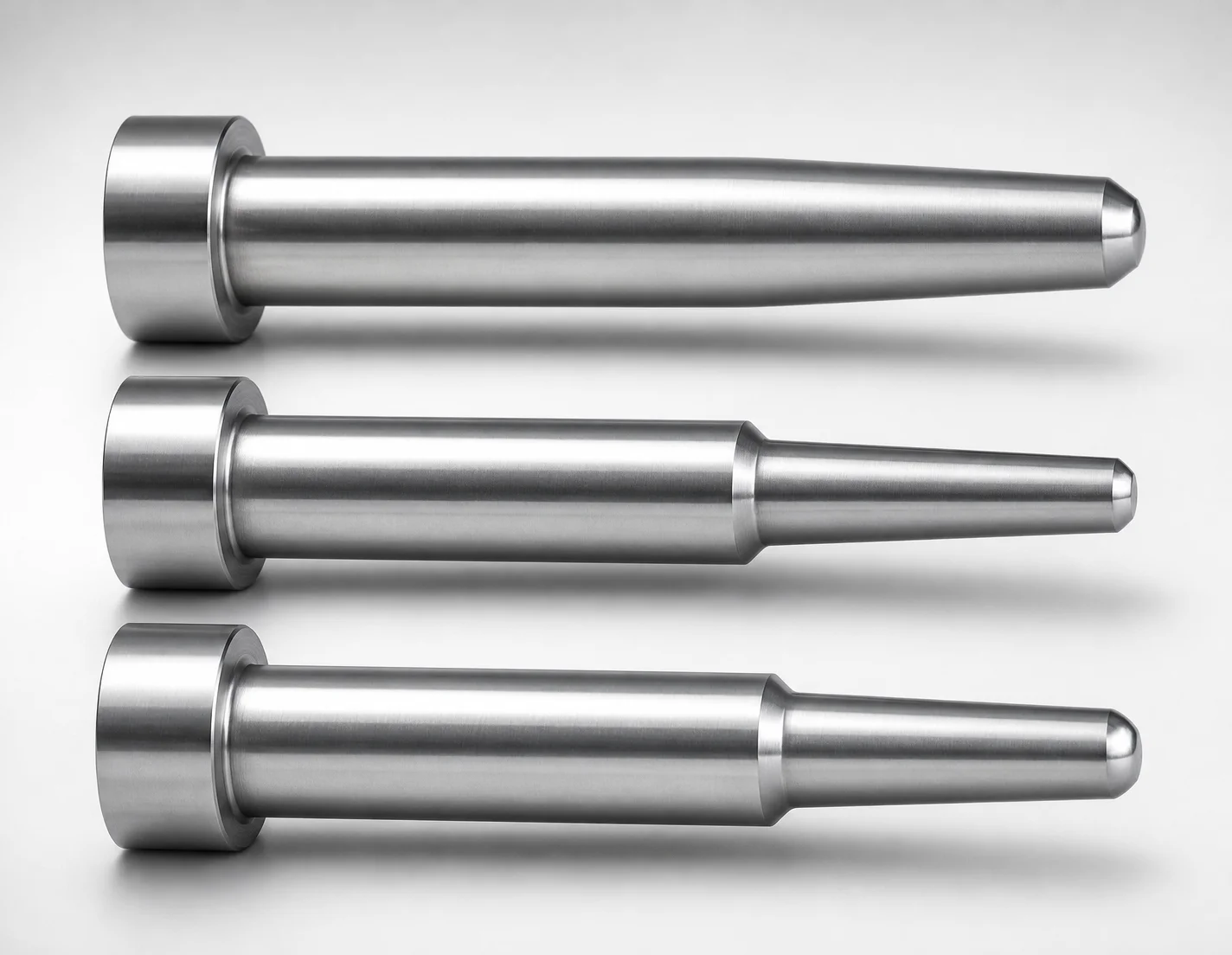
JIS Standard SKH51 Steel One-Step Core Pins - No Second Step
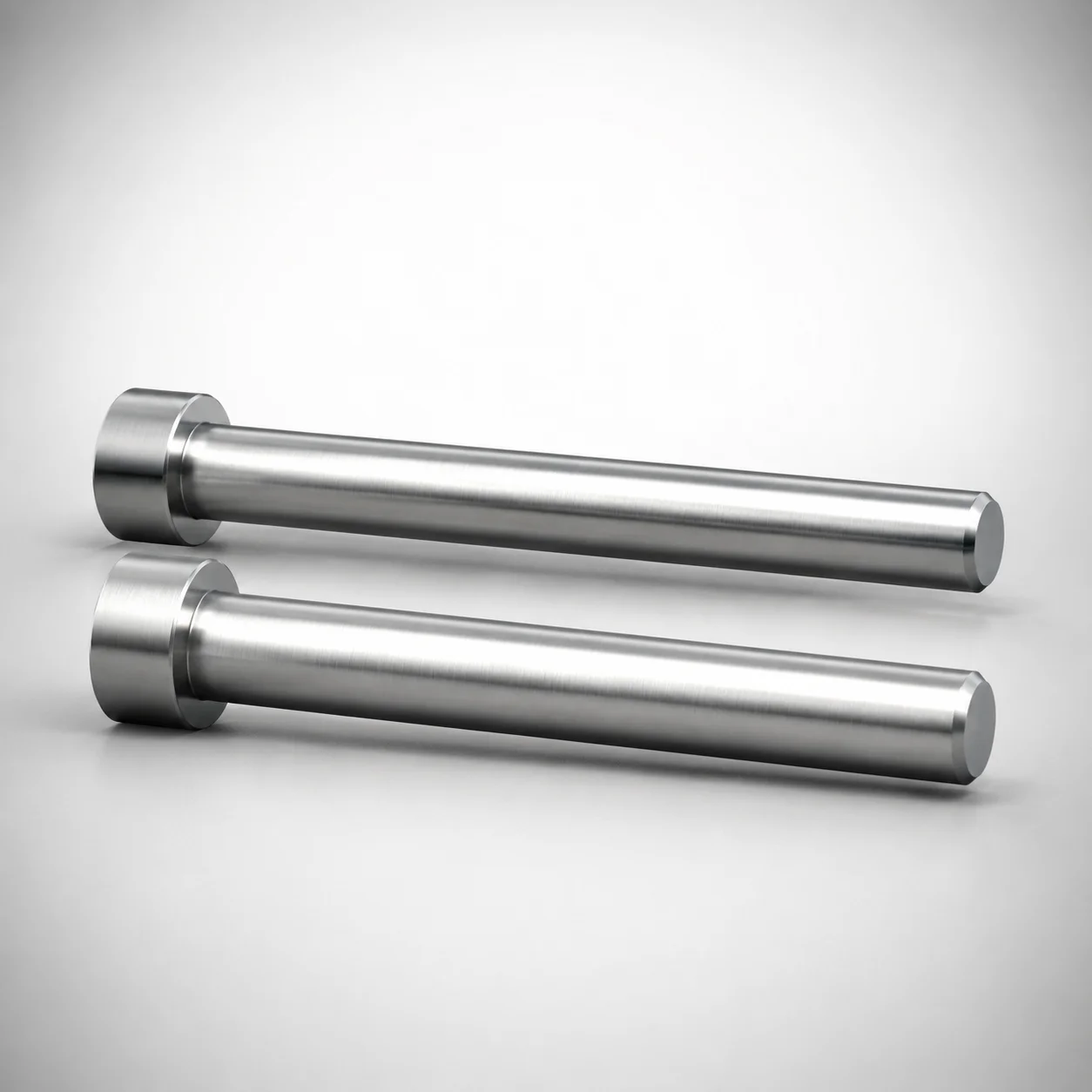
SKH51 Steel Precision Tip Short One-Step Core Pins
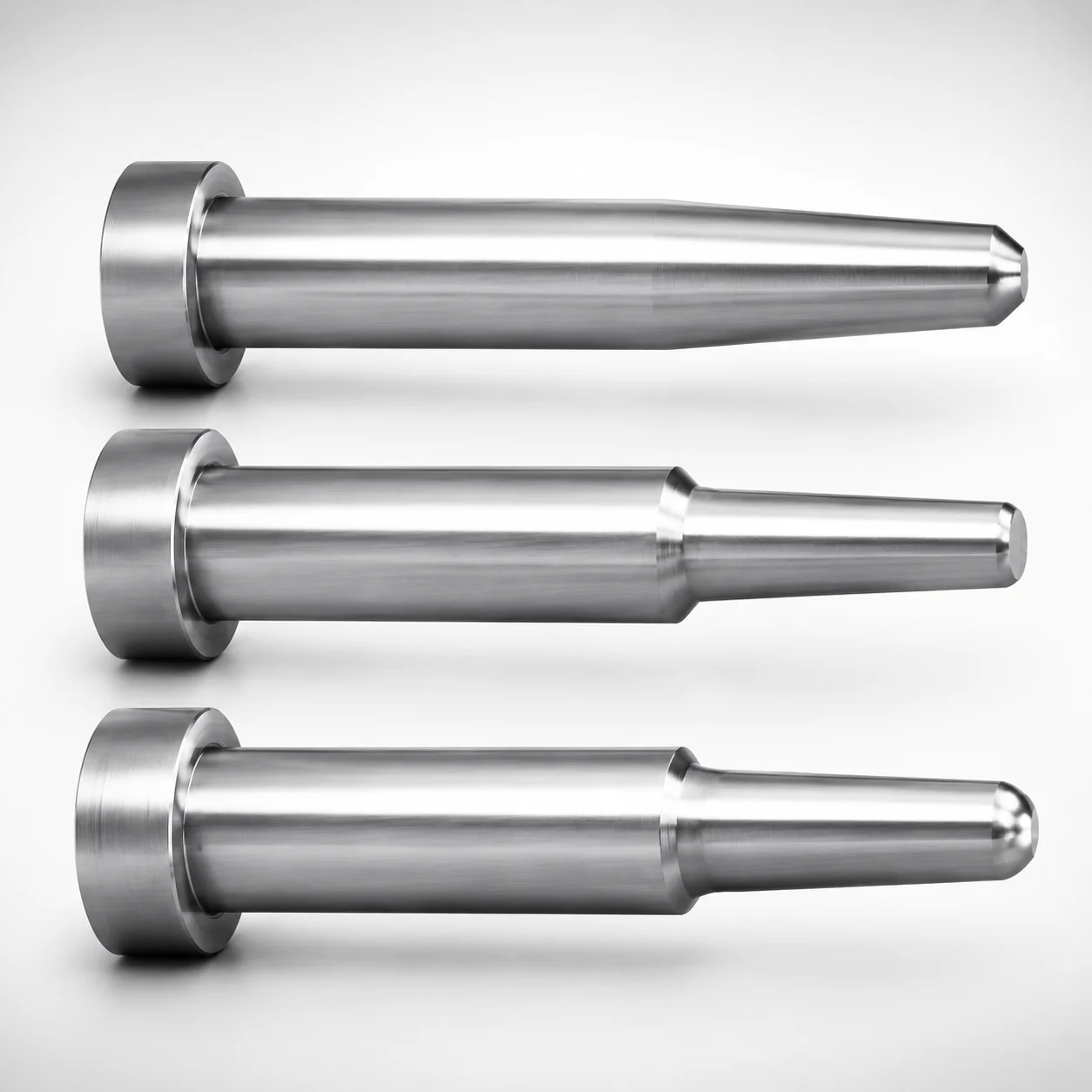
JIS Standard Precision One-Step Core Pins T4 Head
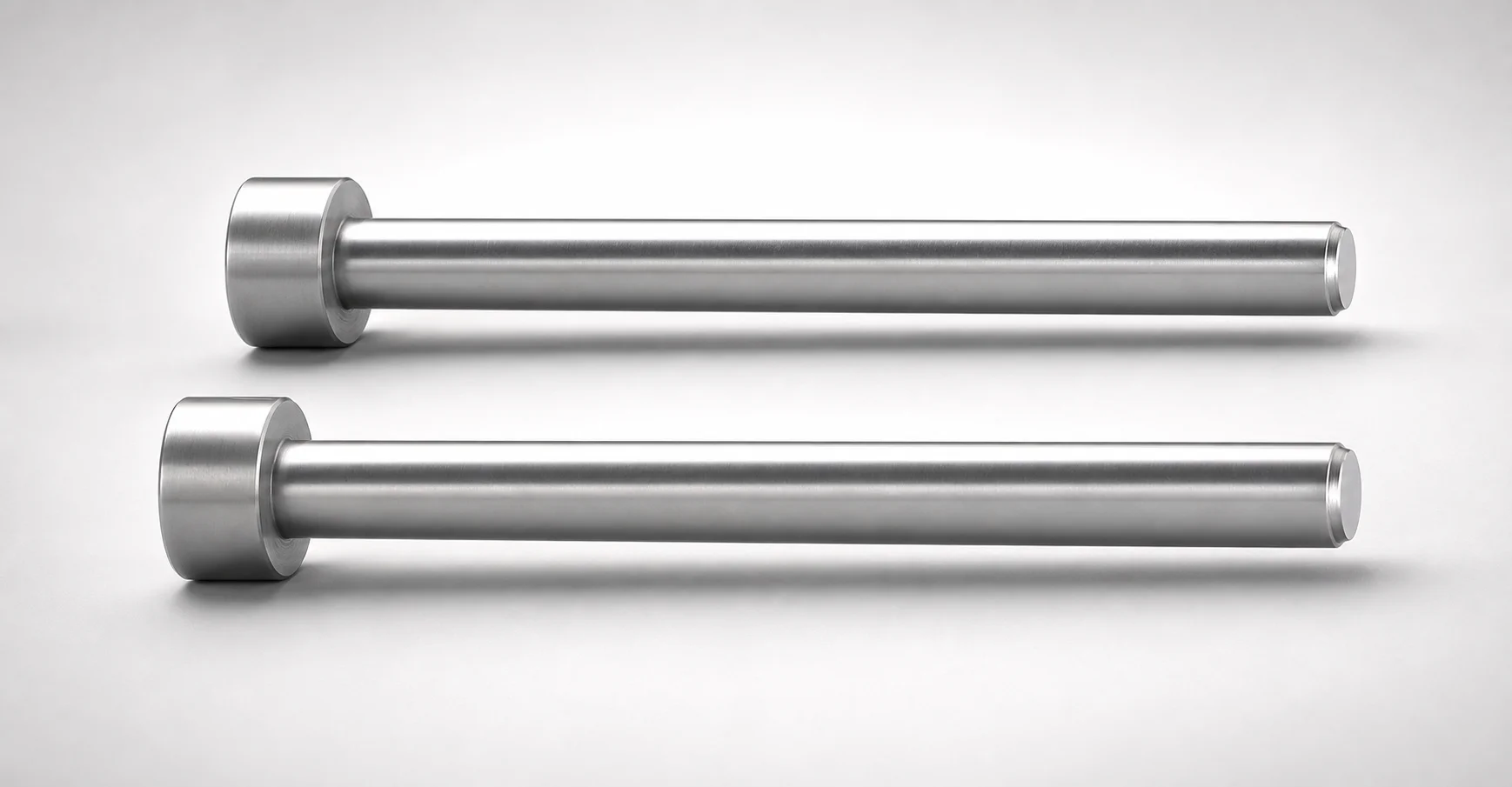
JIS Standard Precision Tip Short One-Step Core Pins
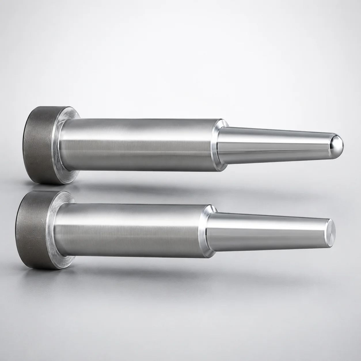
JIS Standard Steel One-Step Core Pins - Tip Lapped
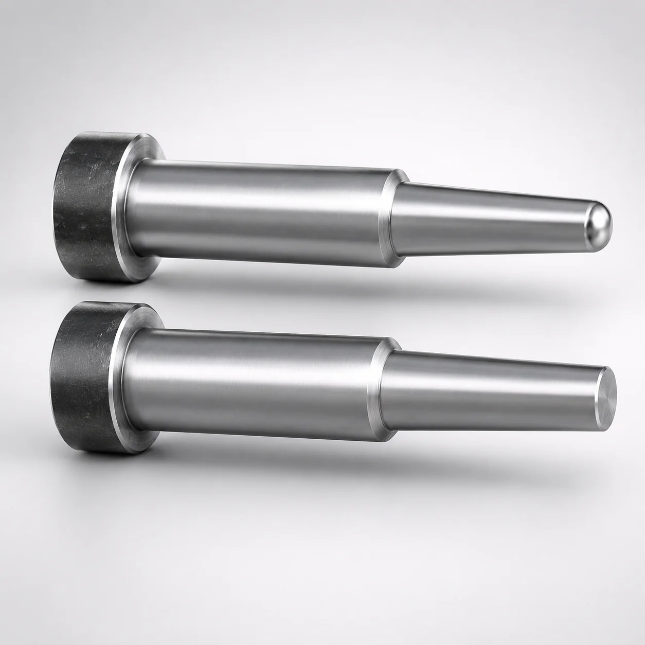
JIS Standard Steel One-Step Core Pins Tip Lapped
Need Custom Specifications?
Our engineering team can help with custom configurations, material selection, and volume pricing.