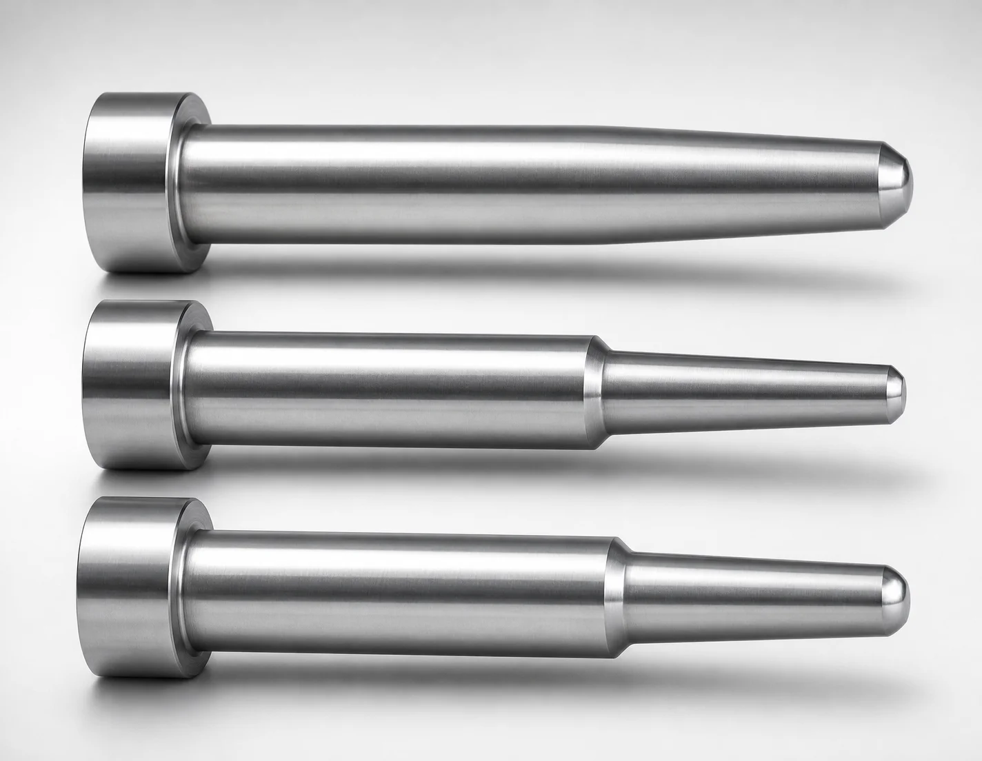
JIS Standard SKH51 Steel One-Step Core Pins - No Second Step
One-step core pins (SKH51 steel) deliver extra precision with a single-step geometry featuring no second step, supporting consistent alignment and reliable ejection performance in precision molds.
- One-step shape with no second step for repeatable positioning and dependable core support
- Made from SKH51 hardened steel for wear resistance in high-cycle molding
- Supports tight fit with shaft diameter tolerance 0/-0.003 for controlled assembly
- Designed to meet precision tip requirements with tip gradient tolerance ±0.005
Specifications
2315 configurations available
| L Dimension Tolerance | D/P (Shaft Diameter) (mm) | First Step Shape | Tip Shape | A (Step shape diameter) (mm) | C (Step type taper width) (mm) | CVC (Designation of C dimension in increments of 0.01mm) (mm) | F (Bearing bore length) (mm) | FC (Makes F dimension shorter than F min) (mm) | G (Tip C chamfering width) (mm) | K (Tip angle) (°) | L (L dimension) (mm) | Q (Tip R chamfering) (mm) | R (Step type R) (mm) | S (Tip tapered width) (mm) | V (Tip diameter) (mm) | VC (V dimension alteration, smaller than V min) (mm) | type |
|---|---|---|---|---|---|---|---|---|---|---|---|---|---|---|---|---|---|
| +0.01/0 | 1 | 1A | No processing | - | - | - | 12 ~ 99.4 | - | - | - | 6.5 ~ 100 | - | - | - | 0.5 ~ 0.99 | - | - |
| +0.01/0 | 1 | 1A | No processing | - | - | - | 12 ~ 99.4 | - | - | - | 6.5 ~ 100 | - | - | - | - | 0.4 ~ 0.49 | - |
| +0.01/0 | 1 | 1A | No processing | - | - | - | - | 5 ~ 11.99 | - | - | 6.5 ~ 100 | - | - | - | 0.5 ~ 0.99 | - | - |
| +0.01/0 | 1 | 1A | No processing | - | - | - | - | 5 ~ 11.99 | - | - | 6.5 ~ 100 | - | - | - | - | 0.4 ~ 0.49 | - |
| +0.01/0 | 1.5 | 1A | No processing | - | - | - | 12 ~ 99.5 | - | - | - | 6.5 ~ 100 | - | - | - | 0.5 ~ 1.49 | - | - |
| +0.01/0 | 1.5 | 1A | No processing | - | - | - | 12 ~ 99.5 | - | - | - | 6.5 ~ 100 | - | - | - | - | 0.4 ~ 0.49 | - |
| +0.01/0 | 1.5 | 1A | No processing | - | - | - | - | 5 ~ 11.99 | - | - | 6.5 ~ 100 | - | - | - | 0.5 ~ 1.49 | - | - |
| +0.01/0 | 1.5 | 1A | No processing | - | - | - | - | 5 ~ 11.99 | - | - | 6.5 ~ 100 | - | - | - | - | 0.4 ~ 0.49 | - |
| +0.01/0 | 2 | 1A | No processing | - | - | - | 12 ~ 99.5 | - | - | - | 6.5 ~ 100 | - | - | - | 0.5 ~ 1.99 | - | - |
| +0.01/0 | 2 | 1A | No processing | - | - | - | 12 ~ 99.5 | - | - | - | 6.5 ~ 100 | - | - | - | - | 0.5 ~ 0.695 | - |
| +0.01/0 | 2 | 1A | No processing | - | - | - | - | 5 ~ 11.99 | - | - | 6.5 ~ 100 | - | - | - | 0.5 ~ 1.99 | - | - |
| +0.01/0 | 2 | 1A | No processing | - | - | - | - | 5 ~ 11.99 | - | - | 6.5 ~ 100 | - | - | - | - | 0.5 ~ 0.695 | - |
| +0.01/0 | 2.5 | 1A | No processing | - | - | - | 12 ~ 99.5 | - | - | - | 6.5 ~ 100 | - | - | - | 0.5 ~ 2.49 | - | - |
| +0.01/0 | 2.5 | 1A | No processing | - | - | - | 12 ~ 99.5 | - | - | - | 6.5 ~ 100 | - | - | - | - | 0.5 ~ 0.69 | - |
| +0.01/0 | 2.5 | 1A | No processing | - | - | - | - | 5 ~ 11.99 | - | - | 6.5 ~ 100 | - | - | - | 0.5 ~ 2.49 | - | - |
| +0.01/0 | 2.5 | 1A | No processing | - | - | - | - | 5 ~ 11.99 | - | - | 6.5 ~ 100 | - | - | - | - | 0.5 ~ 0.69 | - |
| +0.01/0 | 3 | 1A | No processing | - | - | - | 12 ~ 99.5 | - | - | - | 6.5 ~ 100 | - | - | - | 0.7 ~ 2.99 | - | - |
| +0.01/0 | 3 | 1A | No processing | - | - | - | 12 ~ 99.5 | - | - | - | 6.5 ~ 100 | - | - | - | - | 0.7 ~ 0.99 | - |
| +0.01/0 | 3 | 1A | No processing | - | - | - | - | 5 ~ 11.99 | - | - | 6.5 ~ 100 | - | - | - | 0.7 ~ 2.99 | - | - |
| +0.01/0 | 3 | 1A | No processing | - | - | - | - | 5 ~ 11.99 | - | - | 6.5 ~ 100 | - | - | - | - | 0.7 ~ 0.99 | - |
| +0.01/0 | 3.5 | 1A | No processing | - | - | - | 12 ~ 99.5 | - | - | - | 6.5 ~ 100 | - | - | - | 1 ~ 3.49 | - | - |
| +0.01/0 | 3.5 | 1A | No processing | - | - | - | 12 ~ 99.5 | - | - | - | 6.5 ~ 100 | - | - | - | - | 0.7 ~ 0.99 | - |
| +0.01/0 | 3.5 | 1A | No processing | - | - | - | - | 5 ~ 11.99 | - | - | 6.5 ~ 100 | - | - | - | 1 ~ 3.49 | - | - |
| +0.01/0 | 3.5 | 1A | No processing | - | - | - | - | 5 ~ 11.99 | - | - | 6.5 ~ 100 | - | - | - | - | 0.7 ~ 0.99 | - |
| +0.01/0 | 4 | 1A | No processing | - | - | - | 12 ~ 99.5 | - | - | - | 6.5 ~ 100 | - | - | - | 1 ~ 3.99 | - | - |
| +0.01/0 | 4 | 1A | No processing | - | - | - | 12 ~ 99.5 | - | - | - | 6.5 ~ 100 | - | - | - | - | 0.7 ~ 0.99 | - |
| +0.01/0 | 4 | 1A | No processing | - | - | - | - | 5 ~ 11.99 | - | - | 6.5 ~ 100 | - | - | - | 1 ~ 3.99 | - | - |
| +0.01/0 | 4 | 1A | No processing | - | - | - | - | 5 ~ 11.99 | - | - | 6.5 ~ 100 | - | - | - | - | 0.7 ~ 0.99 | - |
| +0.01/0 | 4.5 | 1A | No processing | - | - | - | 12 ~ 99.5 | - | - | - | 6.5 ~ 100 | - | - | - | 1 ~ 4.49 | - | - |
| +0.01/0 | 4.5 | 1A | No processing | - | - | - | 12 ~ 99.5 | - | - | - | 6.5 ~ 100 | - | - | - | - | 1 ~ 1.49 | - |
| +0.01/0 | 4.5 | 1A | No processing | - | - | - | - | 5 ~ 11.99 | - | - | 6.5 ~ 100 | - | - | - | 1 ~ 4.49 | - | - |
| +0.01/0 | 4.5 | 1A | No processing | - | - | - | - | 5 ~ 11.99 | - | - | 6.5 ~ 100 | - | - | - | - | 1 ~ 1.49 | - |
| +0.01/0 | 5 | 1A | No processing | - | - | - | 12 ~ 99.5 | - | - | - | 6.5 ~ 100 | - | - | - | 1 ~ 4.99 | - | - |
| +0.01/0 | 5 | 1A | No processing | - | - | - | 12 ~ 99.5 | - | - | - | 6.5 ~ 100 | - | - | - | - | 1 ~ 1.49 | - |
| +0.01/0 | 5 | 1A | No processing | - | - | - | - | 5 ~ 11.99 | - | - | 6.5 ~ 100 | - | - | - | 1 ~ 4.99 | - | - |
| +0.01/0 | 5 | 1A | No processing | - | - | - | - | 5 ~ 11.99 | - | - | 6.5 ~ 100 | - | - | - | - | 1 ~ 1.49 | - |
| +0.01/0 | 5.5 | 1A | No processing | - | - | - | 12 ~ 99.5 | - | - | - | 6.5 ~ 100 | - | - | - | 1.5 ~ 5.49 | - | - |
| +0.01/0 | 5.5 | 1A | No processing | - | - | - | 12 ~ 99.5 | - | - | - | 6.5 ~ 100 | - | - | - | - | 1 ~ 1.49 | - |
| +0.01/0 | 5.5 | 1A | No processing | - | - | - | - | 5 ~ 11.99 | - | - | 6.5 ~ 100 | - | - | - | 1.5 ~ 5.49 | - | - |
| +0.01/0 | 5.5 | 1A | No processing | - | - | - | - | 5 ~ 11.99 | - | - | 6.5 ~ 100 | - | - | - | - | 1 ~ 1.49 | - |
| +0.01/0 | 6 | 1A | No processing | - | - | - | 12 ~ 99.5 | - | - | - | 6.5 ~ 100 | - | - | - | 2 ~ 5.99 | - | - |
| +0.01/0 | 6 | 1A | No processing | - | - | - | 12 ~ 99.5 | - | - | - | 6.5 ~ 100 | - | - | - | - | 1.5 ~ 1.99 | - |
| +0.01/0 | 6 | 1A | No processing | - | - | - | - | 5 ~ 11.99 | - | - | 6.5 ~ 100 | - | - | - | 2 ~ 5.99 | - | - |
| +0.01/0 | 6 | 1A | No processing | - | - | - | - | 5 ~ 11.99 | - | - | 6.5 ~ 100 | - | - | - | - | 1.5 ~ 1.99 | - |
| +0.01/0 | 6.5 | 1A | No processing | - | - | - | 12 ~ 99.5 | - | - | - | 6.5 ~ 100 | - | - | - | 2 ~ 6.49 | - | - |
| +0.01/0 | 6.5 | 1A | No processing | - | - | - | 12 ~ 99.5 | - | - | - | 6.5 ~ 100 | - | - | - | - | 1.5 ~ 1.99 | - |
| +0.01/0 | 6.5 | 1A | No processing | - | - | - | - | 5 ~ 11.99 | - | - | 6.5 ~ 100 | - | - | - | 2 ~ 6.49 | - | - |
| +0.01/0 | 6.5 | 1A | No processing | - | - | - | - | 5 ~ 11.99 | - | - | 6.5 ~ 100 | - | - | - | - | 1.5 ~ 1.99 | - |
| +0.01/0 | 7 | 1A | No processing | - | - | - | 12 ~ 99.5 | - | - | - | 6.5 ~ 100 | - | - | - | 2 ~ 6.99 | - | - |
| +0.01/0 | 7 | 1A | No processing | - | - | - | 12 ~ 99.5 | - | - | - | 6.5 ~ 100 | - | - | - | - | 1.5 ~ 1.99 | - |
Product Guide
Application Scenarios+
This one-step core pin style is used in injection mold tooling where stable positioning and consistent ejection support are critical, especially for high-cycle, precision cavities. The single-step geometry with no second step reduces risk of misalignment during assembly and repeated plug-in cycles, helping maintain reliable core contact throughout production.
- Automotive and industrial connector molds: Ideal for slender core features and guided ejection areas, where controlled fit and wear resistance support long runs without degradation of the pin’s working surfaces.
- Compact consumer and appliance components: Suited to housings and snap-fit features that require tight core stability; the hardened SKH51 construction supports accurate ejection timing and consistent dimensional retention.
- Small precision molded parts (tight tolerances): The variant’s dimensioning for controlled assembly—such as the shaft diameter tolerance—matches the needs of precision cavity/core interfaces.
Overall, the SKH51 hardened steel and no-second-step design are particularly suited to molds that demand tight fit repeatability and dependable ejection performance.
Material & Process Details+
SKH51 is a JIS standard high-speed steel grade commonly specified for precision mold components where wear resistance at the core contact surface is important. For this variant, the pins are supplied as hardened steel to improve surface durability and reduce growth or rounding under repetitive molding contact.
- Wear resistance vs. toughness: Compared with tougher mold steels, SKH51 prioritizes wear resistance, but typically requires attention to avoid excessive shock loading at thin sections.
- Heat treatment state: The intended condition is hardened; exact hardness value (HRC) and specific tempering temperature are not provided in the supplied data.
- Manufacturing process: Production typically involves machining the stepped and tip geometry, followed by heat treatment and final grinding/polishing to achieve the stated fit and tip gradient tolerances.
If you need a brief comparison with alternative mold steels, SKH51 is selected when surface wear dominates performance. For highly impact-prone applications, a tougher core-pin alloy may be considered in design—however, this product variant is specifically defined for SKH51 hardened steel performance.
Sizing & Selection Guide+
To select the correct one-step core pin dimensions, start by matching the shaft diameter D/P to your core/cavity guide bore requirements. This product supports D/P = 1 ~ 13 mm with a specified shaft fit tolerance of 0/-0.003, which is intended for controlled assembly (slight undersize to maintain predictable clearance or interference strategy based on your mating bore).
- Pin length (L): Use the offered L ranges—6.5 ~ 100 mm and 14 ~ 100 mm depending on configuration—ensuring the working tip reaches the required core depth without bottoming.
- Step geometry: Choose the first step shape (1A–1E) and set the step shape diameter A = 0.5 ~ 2 mm to match the corresponding stop/shoulder interface in your tool.
- Tip and gradient control: Select the tip shape (No processing, B, C, G, R, T) and verify tip gradient tolerance ±0.005 for alignment and ejection consistency at the core end.
Confirm tolerance stack-up on the mating part because only the pin’s stated tolerances are defined here (including L dimension tolerance: +0.01/0 and 0/-0.05, depending on configuration).
Frequently Asked Questions
What does the “one-step” design mean in terms of core pin alignment performance?+
How tight is the fit on the shaft diameter, and what clearance strategy should we plan?+
How should we choose L length when multiple L ranges are available?+
What tip geometries are available, and where does the tip gradient tolerance apply?+
Is SKH51 suitable for high-wear applications, and what trade-off should we consider?+
Related Products
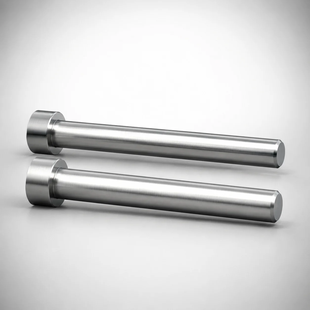
SKH51 Steel Precision Tip Short One-Step Core Pins
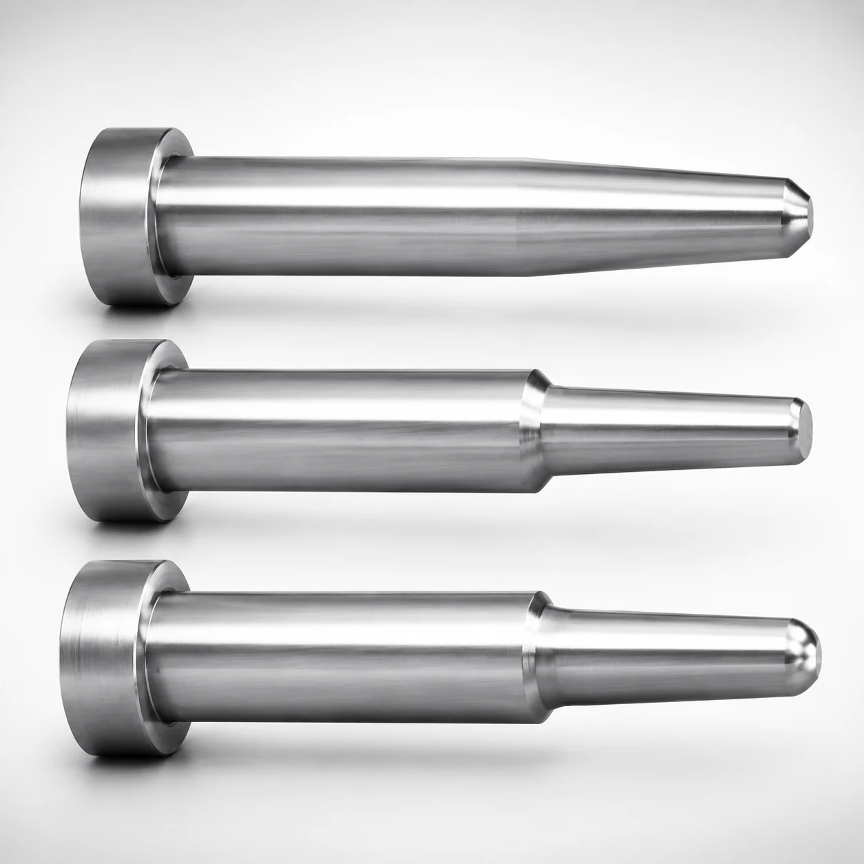
JIS Standard Precision One-Step Core Pins T4 Head
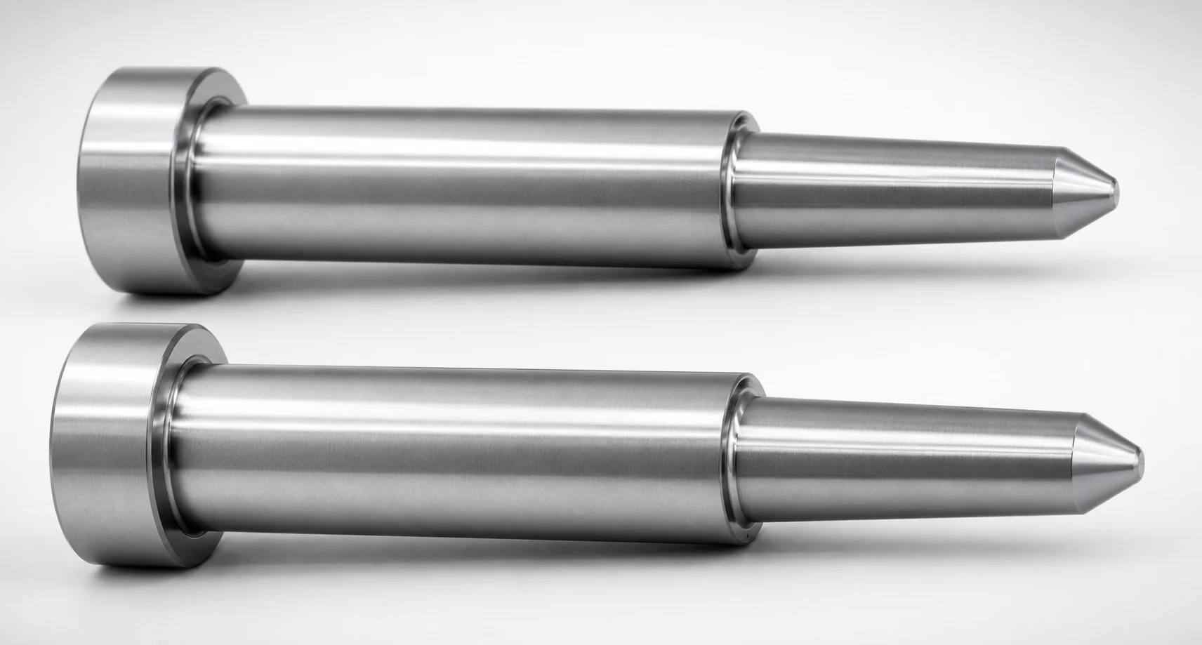
JIS Standard Precision One-Step Core Pins No Second Step
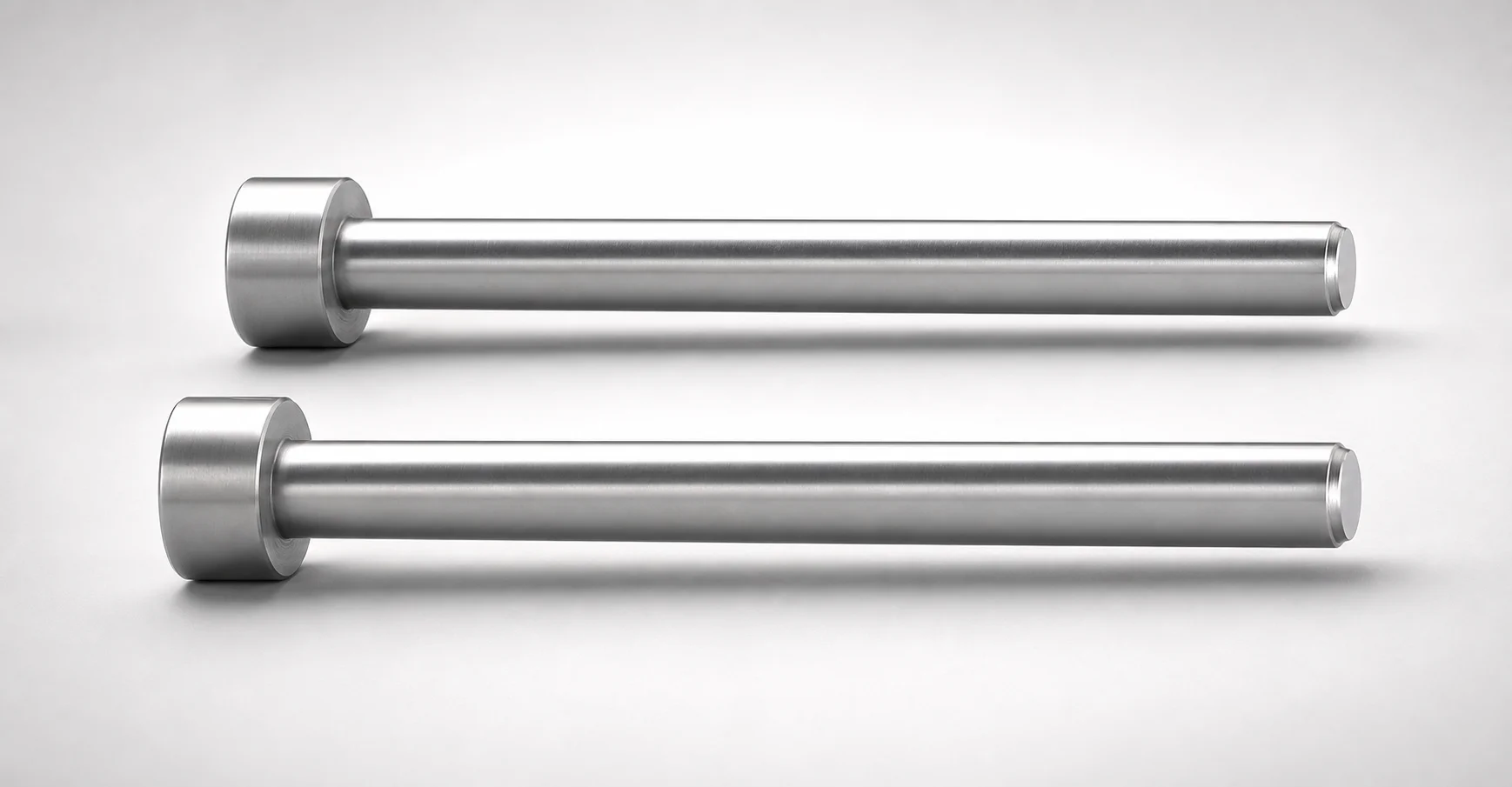
JIS Standard Precision Tip Short One-Step Core Pins
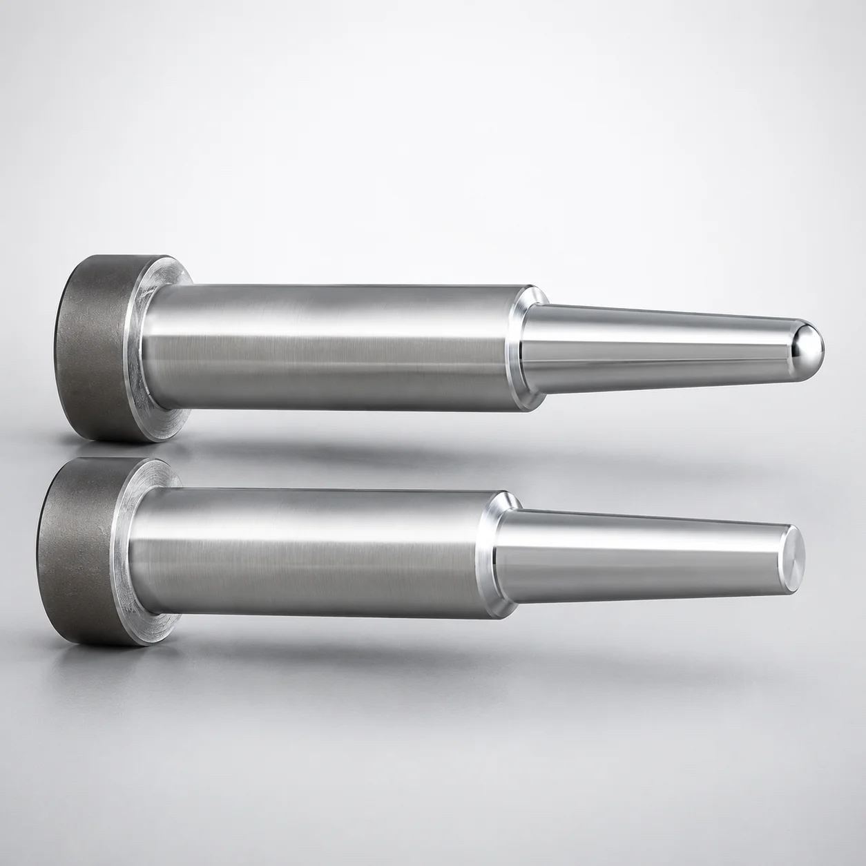
JIS Standard Steel One-Step Core Pins - Tip Lapped
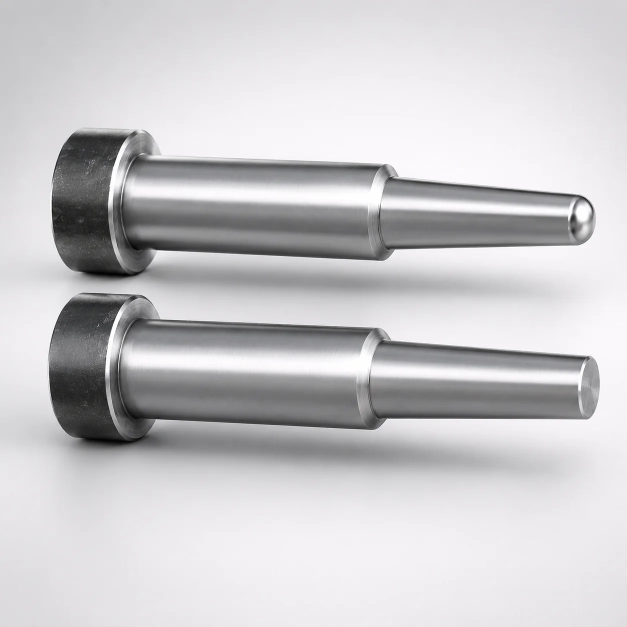
JIS Standard Steel One-Step Core Pins Tip Lapped
Need Custom Specifications?
Our engineering team can help with custom configurations, material selection, and volume pricing.