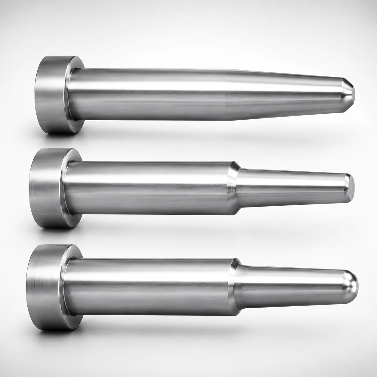
JIS Standard Precision One-Step Core Pins T4 Head
Precision One-Step Core Pins (SKH51 or SKD61 steel) with a T4 head provide consistent core positioning and one-step seating for repeatable mold assembly. The one-step geometry and controlled tip profile help maintain alignment in high-cycle production.
- One-step design with No second step simplifies engagement and improves repeatability
- Selectable SKH51/SKD61 hardened steel supports reliable wear resistance for tooling use
- Tight shaft and tip gradient tolerances for stable core support during operation
- Built for precision mold applications where controlled tip geometry and head seating matter
Specifications
5192 configurations available
| Material | L Dimension Tolerance | D/P (Shaft Diameter) (mm) | First Step Shape | Tip Shape | A (Step shape diameter) (mm) | C (Step type taper width) (mm) | CVC (Designation of C dimension in increments of 0.01mm) (mm) | F (Bearing bore length) (mm) | FC (Makes F dimension shorter than F min) (mm) | G (Tip C chamfering width) (mm) | K (Tip angle) (°) | L (L dimension) (mm) | Q (Tip R chamfering) (mm) | R (Step type R) (mm) | S (Tip tapered width) (mm) | V (Tip diameter) (mm) | VC (V dimension alteration, smaller than V min) (mm) | type |
|---|---|---|---|---|---|---|---|---|---|---|---|---|---|---|---|---|---|---|
| SKH51 | +0.01/0 | 1 | 1A | No processing | - | - | - | 12 ~ 96 | - | - | - | 6.5 ~ 100 | - | - | - | 0.5 ~ 0.99 | - | - |
| SKH51 | +0.01/0 | 1 | 1A | No processing | - | - | - | 12 ~ 96 | - | - | - | 6.5 ~ 100 | - | - | - | - | 0.4 ~ 0.49 | - |
| SKH51 | +0.01/0 | 1 | 1A | No processing | - | - | - | - | 5 ~ 11.99 | - | - | 6.5 ~ 100 | - | - | - | 0.5 ~ 0.99 | - | - |
| SKH51 | +0.01/0 | 1 | 1A | No processing | - | - | - | - | 5 ~ 11.99 | - | - | 6.5 ~ 100 | - | - | - | - | 0.4 ~ 0.49 | - |
| SKH51 | +0.01/0 | 1.5 | 1A | No processing | - | - | - | 12 ~ 96 | - | - | - | 6.5 ~ 100 | - | - | - | 0.5 ~ 1.49 | - | - |
| SKH51 | +0.01/0 | 1.5 | 1A | No processing | - | - | - | 12 ~ 96 | - | - | - | 6.5 ~ 100 | - | - | - | - | 0.4 ~ 0.49 | - |
| SKH51 | +0.01/0 | 1.5 | 1A | No processing | - | - | - | - | 5 ~ 11.99 | - | - | 6.5 ~ 100 | - | - | - | 0.5 ~ 1.49 | - | - |
| SKH51 | +0.01/0 | 1.5 | 1A | No processing | - | - | - | - | 5 ~ 11.99 | - | - | 6.5 ~ 100 | - | - | - | - | 0.4 ~ 0.49 | - |
| SKH51 | +0.01/0 | 2 | 1A | No processing | - | - | - | 12 ~ 96 | - | - | - | 6.5 ~ 100 | - | - | - | 0.5 ~ 1.99 | - | - |
| SKH51 | +0.01/0 | 2 | 1A | No processing | - | - | - | 12 ~ 96 | - | - | - | 6.5 ~ 100 | - | - | - | - | 0.5 ~ 0.69 | - |
| SKH51 | +0.01/0 | 2 | 1A | No processing | - | - | - | - | 5 ~ 11.99 | - | - | 6.5 ~ 100 | - | - | - | 0.5 ~ 1.99 | - | - |
| SKH51 | +0.01/0 | 2 | 1A | No processing | - | - | - | - | 5 ~ 11.99 | - | - | 6.5 ~ 100 | - | - | - | - | 0.5 ~ 0.69 | - |
| SKH51 | +0.01/0 | 2.5 | 1A | No processing | - | - | - | 12 ~ 96 | - | - | - | 6.5 ~ 100 | - | - | - | 0.5 ~ 2.49 | - | - |
| SKH51 | +0.01/0 | 2.5 | 1A | No processing | - | - | - | 12 ~ 96 | - | - | - | 6.5 ~ 100 | - | - | - | - | 0.5 ~ 0.69 | - |
| SKH51 | +0.01/0 | 2.5 | 1A | No processing | - | - | - | - | 5 ~ 11.99 | - | - | 6.5 ~ 100 | - | - | - | 0.5 ~ 2.49 | - | - |
| SKH51 | +0.01/0 | 2.5 | 1A | No processing | - | - | - | - | 5 ~ 11.99 | - | - | 6.5 ~ 100 | - | - | - | - | 0.5 ~ 0.69 | - |
| SKH51 | +0.01/0 | 3 | 1A | No processing | - | - | - | 12 ~ 96 | - | - | - | 6.5 ~ 100 | - | - | - | 0.7 ~ 2.99 | - | - |
| SKH51 | +0.01/0 | 3 | 1A | No processing | - | - | - | 12 ~ 96 | - | - | - | 6.5 ~ 100 | - | - | - | - | 0.7 ~ 0.99 | - |
| SKH51 | +0.01/0 | 3 | 1A | No processing | - | - | - | - | 5 ~ 11.99 | - | - | 6.5 ~ 100 | - | - | - | 0.7 ~ 2.99 | - | - |
| SKH51 | +0.01/0 | 3 | 1A | No processing | - | - | - | - | 5 ~ 11.99 | - | - | 6.5 ~ 100 | - | - | - | - | 0.7 ~ 0.99 | - |
| SKH51 | +0.01/0 | 3.5 | 1A | No processing | - | - | - | 12 ~ 116 | - | - | - | 6.5 ~ 120 | - | - | - | 1 ~ 3.49 | - | - |
| SKH51 | +0.01/0 | 3.5 | 1A | No processing | - | - | - | 12 ~ 116 | - | - | - | 6.5 ~ 120 | - | - | - | - | 0.7 ~ 0.99 | - |
| SKH51 | +0.01/0 | 3.5 | 1A | No processing | - | - | - | - | 5 ~ 11.99 | - | - | 6.5 ~ 120 | - | - | - | 1 ~ 3.49 | - | - |
| SKH51 | +0.01/0 | 3.5 | 1A | No processing | - | - | - | - | 5 ~ 11.99 | - | - | 6.5 ~ 120 | - | - | - | - | 0.7 ~ 0.99 | - |
| SKH51 | +0.01/0 | 4 | 1A | No processing | - | - | - | 12 ~ 116 | - | - | - | 6.5 ~ 120 | - | - | - | 1 ~ 3.99 | - | - |
| SKH51 | +0.01/0 | 4 | 1A | No processing | - | - | - | 12 ~ 116 | - | - | - | 6.5 ~ 120 | - | - | - | - | 0.7 ~ 0.99 | - |
| SKH51 | +0.01/0 | 4 | 1A | No processing | - | - | - | - | 5 ~ 11.99 | - | - | 6.5 ~ 120 | - | - | - | 1 ~ 3.99 | - | - |
| SKH51 | +0.01/0 | 4 | 1A | No processing | - | - | - | - | 5 ~ 11.99 | - | - | 6.5 ~ 120 | - | - | - | - | 0.7 ~ 0.99 | - |
| SKH51 | +0.01/0 | 4.5 | 1A | No processing | - | - | - | 12 ~ 116 | - | - | - | 6.5 ~ 120 | - | - | - | 1 ~ 4.49 | - | - |
| SKH51 | +0.01/0 | 4.5 | 1A | No processing | - | - | - | 12 ~ 116 | - | - | - | 6.5 ~ 120 | - | - | - | - | 1 ~ 1.49 | - |
| SKH51 | +0.01/0 | 4.5 | 1A | No processing | - | - | - | - | 5 ~ 11.99 | - | - | 6.5 ~ 120 | - | - | - | 1 ~ 4.49 | - | - |
| SKH51 | +0.01/0 | 4.5 | 1A | No processing | - | - | - | - | 5 ~ 11.99 | - | - | 6.5 ~ 120 | - | - | - | - | 1 ~ 1.49 | - |
| SKH51 | +0.01/0 | 5 | 1A | No processing | - | - | - | 12 ~ 149.99 | - | - | - | 6.5 ~ 150 | - | - | - | 1 ~ 4.99 | - | - |
| SKH51 | +0.01/0 | 5 | 1A | No processing | - | - | - | 12 ~ 149.99 | - | - | - | 6.5 ~ 150 | - | - | - | - | 1 ~ 1.49 | - |
| SKH51 | +0.01/0 | 5 | 1A | No processing | - | - | - | - | 5 ~ 11.99 | - | - | 6.5 ~ 150 | - | - | - | 1 ~ 4.99 | - | - |
| SKH51 | +0.01/0 | 5 | 1A | No processing | - | - | - | - | 5 ~ 11.99 | - | - | 6.5 ~ 150 | - | - | - | - | 1 ~ 1.49 | - |
| SKH51 | +0.01/0 | 5.5 | 1A | No processing | - | - | - | 12 ~ 149.99 | - | - | - | 6.5 ~ 150 | - | - | - | 1.5 ~ 5.49 | - | - |
| SKH51 | +0.01/0 | 5.5 | 1A | No processing | - | - | - | 12 ~ 149.99 | - | - | - | 6.5 ~ 150 | - | - | - | - | 1 ~ 1.49 | - |
| SKH51 | +0.01/0 | 5.5 | 1A | No processing | - | - | - | - | 5 ~ 11.99 | - | - | 6.5 ~ 150 | - | - | - | 1.5 ~ 5.49 | - | - |
| SKH51 | +0.01/0 | 5.5 | 1A | No processing | - | - | - | - | 5 ~ 11.99 | - | - | 6.5 ~ 150 | - | - | - | - | 1 ~ 1.49 | - |
| SKH51 | +0.01/0 | 6 | 1A | No processing | - | - | - | 12 ~ 149.99 | - | - | - | 6.5 ~ 150 | - | - | - | 2 ~ 5.99 | - | - |
| SKH51 | +0.01/0 | 6 | 1A | No processing | - | - | - | 12 ~ 149.99 | - | - | - | 6.5 ~ 150 | - | - | - | - | 1.5 ~ 1.99 | - |
| SKH51 | +0.01/0 | 6 | 1A | No processing | - | - | - | - | 5 ~ 11.99 | - | - | 6.5 ~ 150 | - | - | - | 2 ~ 5.99 | - | - |
| SKH51 | +0.01/0 | 6 | 1A | No processing | - | - | - | - | 5 ~ 11.99 | - | - | 6.5 ~ 150 | - | - | - | - | 1.5 ~ 1.99 | - |
| SKH51 | +0.01/0 | 6.5 | 1A | No processing | - | - | - | 12 ~ 149.99 | - | - | - | 6.5 ~ 150 | - | - | - | 2 ~ 6.49 | - | - |
| SKH51 | +0.01/0 | 6.5 | 1A | No processing | - | - | - | 12 ~ 149.99 | - | - | - | 6.5 ~ 150 | - | - | - | - | 1.5 ~ 1.99 | - |
| SKH51 | +0.01/0 | 6.5 | 1A | No processing | - | - | - | - | 5 ~ 11.99 | - | - | 6.5 ~ 150 | - | - | - | 2 ~ 6.49 | - | - |
| SKH51 | +0.01/0 | 6.5 | 1A | No processing | - | - | - | - | 5 ~ 11.99 | - | - | 6.5 ~ 150 | - | - | - | - | 1.5 ~ 1.99 | - |
| SKH51 | +0.01/0 | 7 | 1A | No processing | - | - | - | 12 ~ 149.99 | - | - | - | 6.5 ~ 150 | - | - | - | 2 ~ 6.99 | - | - |
| SKH51 | +0.01/0 | 7 | 1A | No processing | - | - | - | 12 ~ 149.99 | - | - | - | 6.5 ~ 150 | - | - | - | - | 1.5 ~ 1.99 | - |
Product Guide
Application Scenarios+
These precision one-step core pins are used to support and locate cores in injection mold assemblies where repeatable seating and stable alignment are required. The T4 head provides a positive, one-step interface that helps maintain core position through repeated closing cycles, reducing the risk of drift caused by partial seating.
- Automotive connector and terminal molds: Apply for multi-cavity tooling where controlled shaft/tip gradient tolerances help ensure consistent core-to-cavity alignment during high-cycle production.
- Electronic housings and small-part molds: The compact stepped geometry and stable head seating support precise part features while enabling straightforward assembly engagement.
- Medical device housing inserts: Use the SKH51 or SKD61 variant to balance dimensional stability and wear resistance for long runs where consistent core placement is critical.
Choose this variant when your design relies on one-step seating accuracy (no second step engagement) and precise tip geometry to preserve alignment over time.
Material & Process Details+
Material options are SKH51 or SKD61, both selected for mold tooling wear resistance and dimensional stability. SKH51 is a high-speed steel grade (commonly associated with AISI M2 class performance) that is typically chosen when higher wear resistance is needed. SKD61 is a chromium-molybdenum hot-work die steel (commonly associated with H13 class performance), often selected for a balanced toughness-to-wear profile in injection tooling.
- Heat treatment state: Supplied as a hardened, precision core pin suitable for tooling service; final HRC targets depend on the selected grade and manufacturer heat cycle.
- Hardness & trade-offs: Higher hardenability and wear resistance generally improve tip life, while the toughness balance differs by grade (SKD61 typically prioritizes toughness stability; SKH51 can emphasize wear performance).
- Manufacturing: Ground/finished shaft and tip profiles are controlled to achieve the stated tight tolerances, supporting reliable one-step seating and alignment.
When selecting between grades, base the choice on whether your dominant risk is tip wear (favor SKH51) or toughness under thermal/mechanical cycling (favor SKD61).
Sizing & Selection Guide+
To select the correct one-step core pin, match the shaft diameter and overall length to your core support bore and core placement requirements. The shaft diameter range is D/P = 1 ~ 20 mm, and the L dimension range is L = 6.5 ~ 7 mm. Use the specified step geometry to ensure proper one-step seating: choose the First Step Shape (1A ~ 1E), then select the A step diameter (0.4 ~ 5 mm), and the taper/step parameters (for example CVC = 0.1 ~ 1 mm increments and C taper width options).
- Head seating: The T4 head design provides the one-step interface; ensure your core support stack-up allows full head engagement without interference.
- Tip profile: Select the Tip Shape (No processing, B, C, G, R, T) and the associated tip dimensions (e.g., K = 21 ~ 60° depending on option, Q = 0.2, S = 0.1).
- Tolerance/fit: L dimension tolerance is +0.01/0, 0/-0.1. When mating to the mold body, account for this tolerance stack so the pin seats consistently without excessive clearance.
Frequently Asked Questions
Which steel grade should I select for a high-cycle core support—SKH51 or SKD61?+
Choose SKH51 when tip wear resistance is a primary concern and you need strong wear performance for long runs. Choose SKD61 when you want a more balanced tooling profile that supports toughness under injection mold thermal/mechanical cycling.
The product is offered in SKH51 or SKD61, so your grade selection can be aligned to your failure mode (wear vs. toughness).
How do I size the core pin shaft diameter (D/P) and length (L) to match my mold core support?+
Match D/P (shaft diameter) to your receiving bore requirement within 1 ~ 20 mm. Then set L to fall within 6.5 ~ 7 mm.
Because L has a tolerance of +0.01/0, 0/-0.1, verify that your assembly stack tolerances still allow stable one-step seating.
What does the “T4 head” one-step design imply for mold assembly repeatability?+
The one-step geometry provides a seating interface that avoids a second-step engagement, improving repeatability of core placement during mold closing.
Use the T4 head where your design depends on controlled head seating and stable alignment across high-cycle production, especially when tip gradient/tip profile tolerances matter.
How do I choose the tip geometry options (Tip Shape and K angle) for proper core alignment?+
Select the Tip Shape from the available options (No processing, B, C, G, R, T) to match your desired engagement behavior. Then confirm the K tip angle falls within the allowed ranges (e.g., 21 ~ 60° or 10 ~ 45°, depending on the configuration).
Also verify fixed/controlled tip dimensions such as Q = 0.2, R = 0.2, and S = 0.1 as applicable to your selected variant.
How do the step parameters (First Step Shape, A, and C/CVC) affect selection?+
Your stepped interface is defined by First Step Shape (1A ~ 1E), the step diameter A (0.4 ~ 5 mm), and taper-related parameters like CVC (0.1 ~ 1 mm) and the C taper width options.
Pick these values so the one-step seating and head engagement occur without interference while maintaining stable support geometry for your core.
Related Products
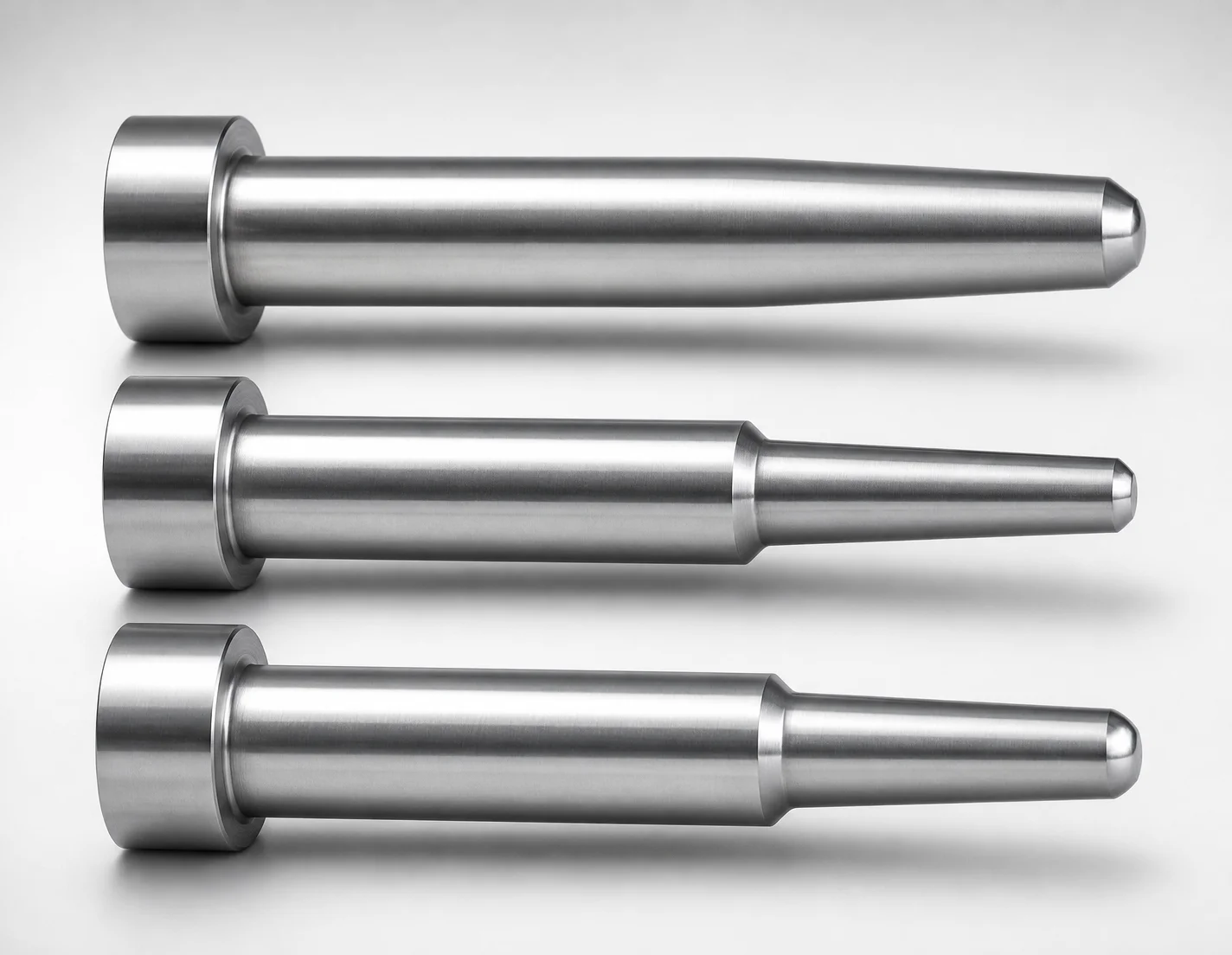
JIS Standard SKH51 Steel One-Step Core Pins - No Second Step
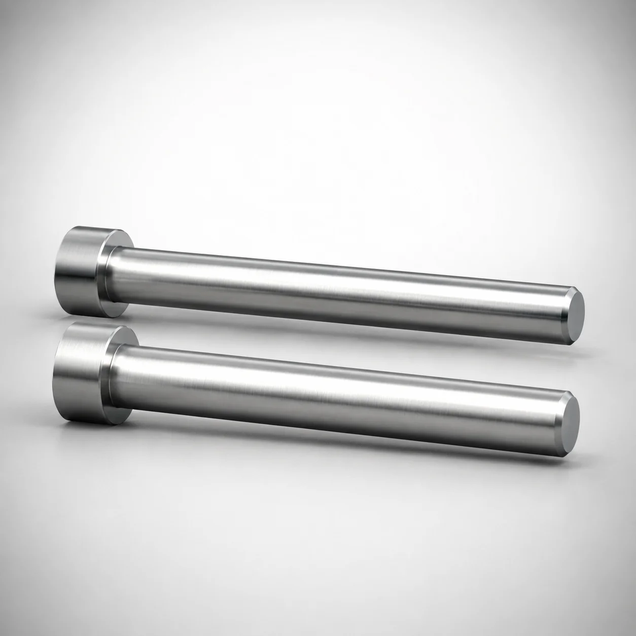
SKH51 Steel Precision Tip Short One-Step Core Pins
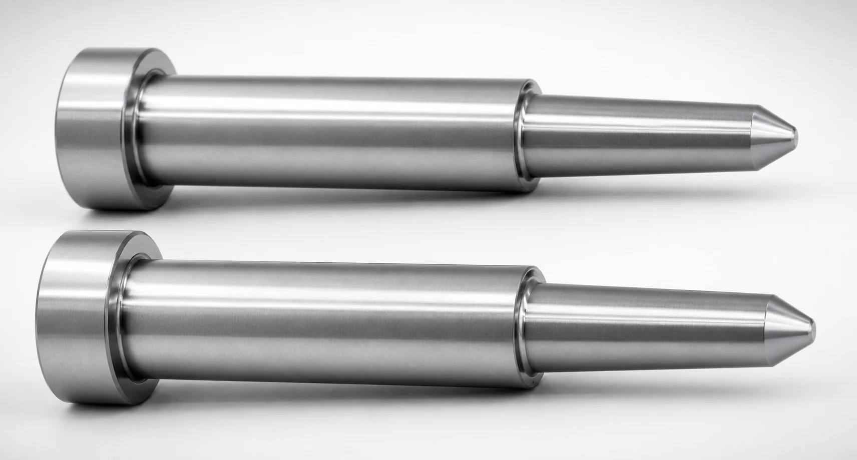
JIS Standard Precision One-Step Core Pins No Second Step
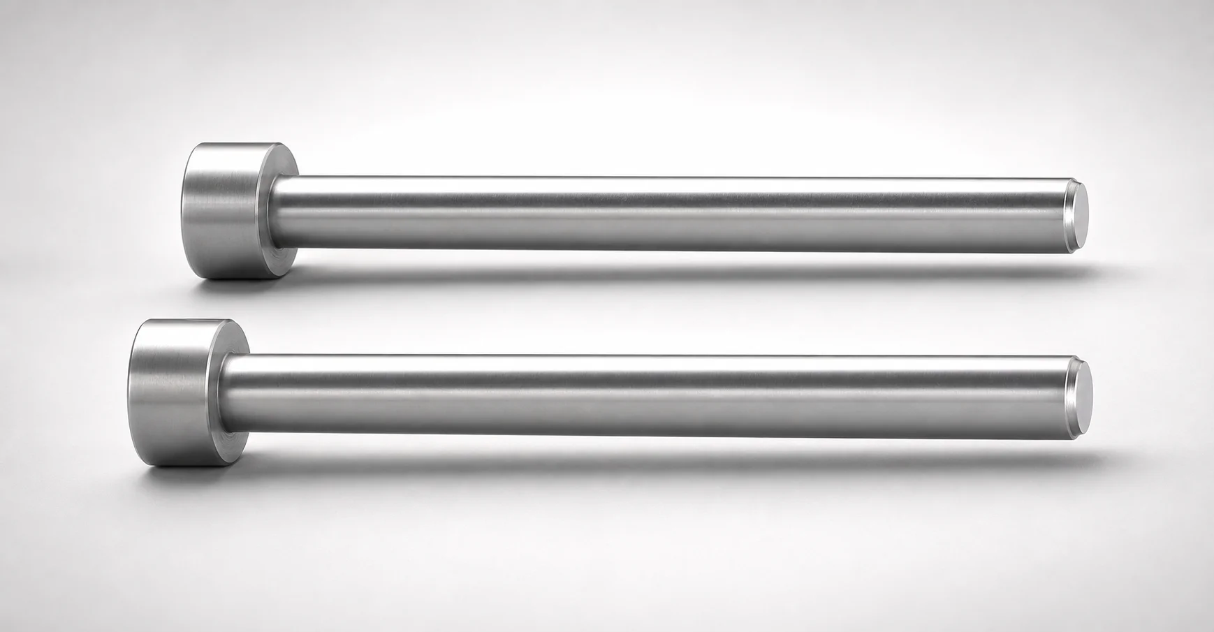
JIS Standard Precision Tip Short One-Step Core Pins
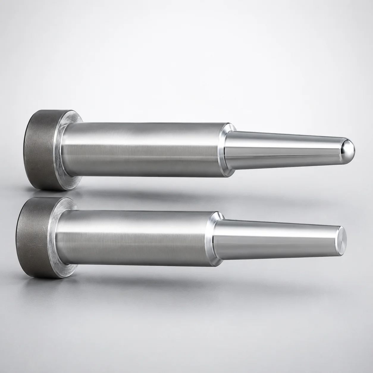
JIS Standard Steel One-Step Core Pins - Tip Lapped
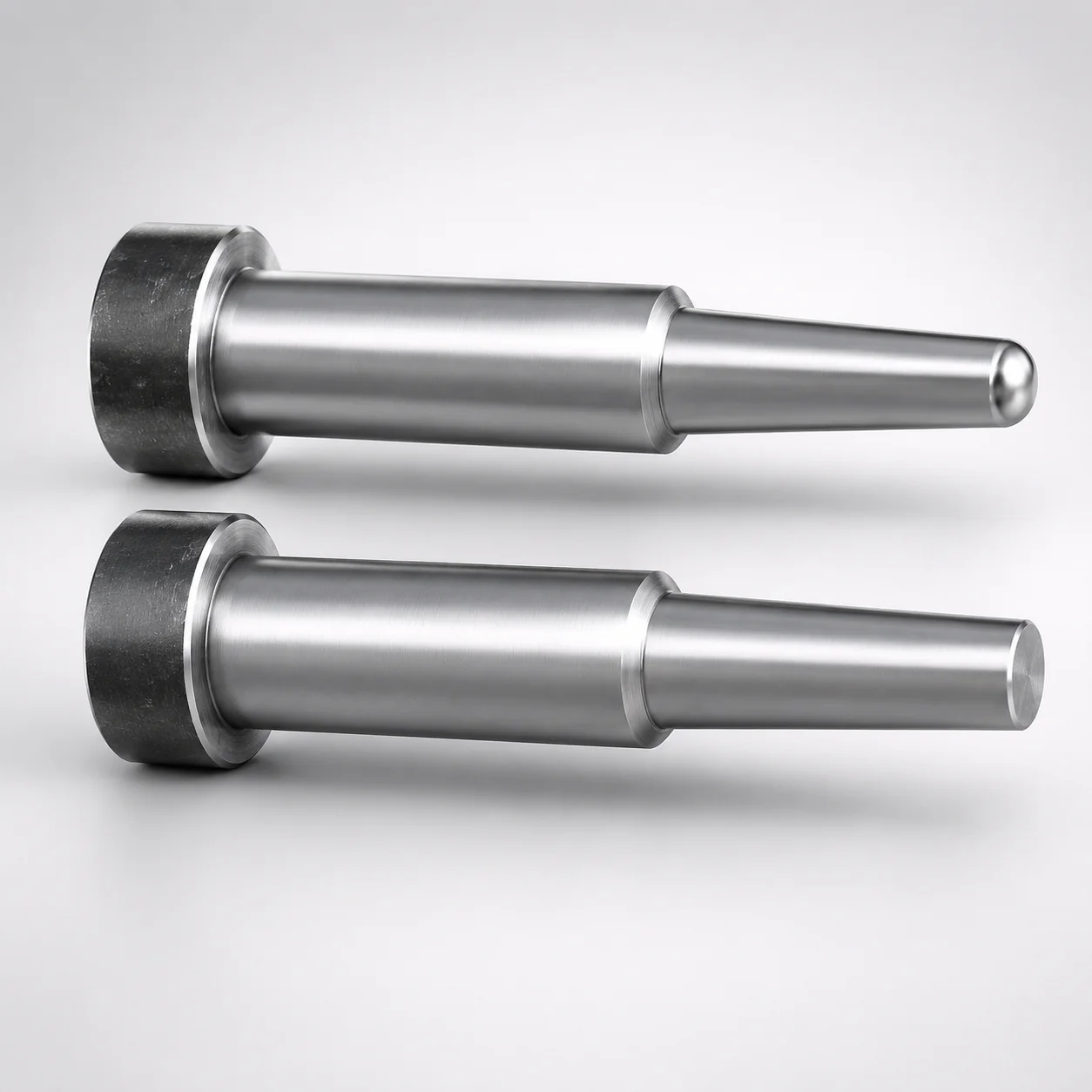
JIS Standard Steel One-Step Core Pins Tip Lapped
Need Custom Specifications?
Our engineering team can help with custom configurations, material selection, and volume pricing.