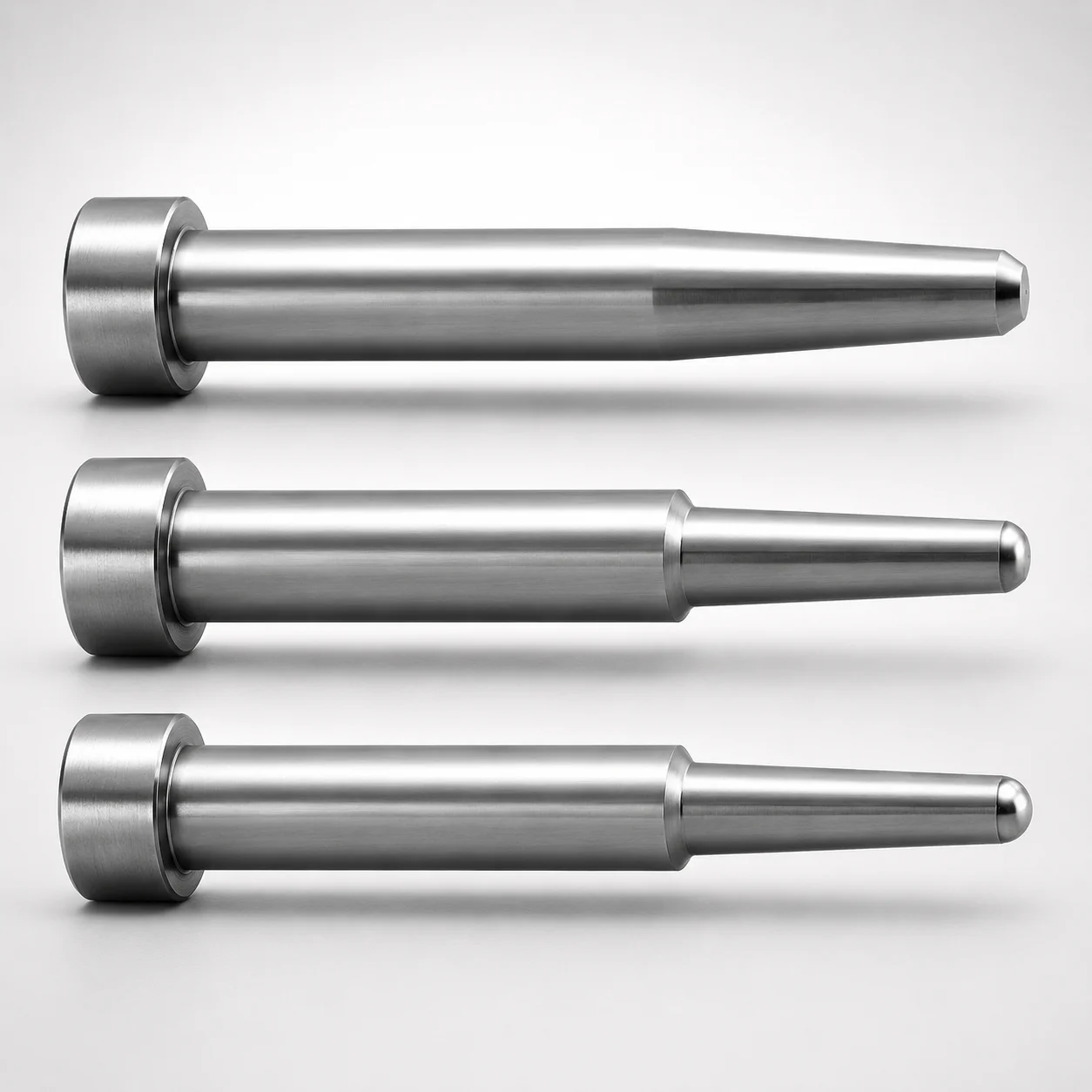
One-Step Core Pins T4 Head Thickness
One-Step Core Pins (selectable steel grades) with T4 head thickness provide stable core location and consistent ejection alignment in precision mold setups. The one-step design simplifies installation while supporting repeatable fit.
- One-step core pin geometry with no second step for streamlined mold layout
- Selectable steel options for tailored wear resistance and dimensional stability
- Supports tight L dimension tolerances (+0.02/0 or 0/-0.1) for accurate assembly
- Compatible with core positioning applications requiring repeatable alignment
Specifications
15671 configurations available
| Material | Shaft Diameter Tolerance | L Dimension Tolerance | Tip Gradient Tolerance | D/P (Shaft Diameter) (mm) | First Step Shape | Tip Shape | No. (Nominal diameter) (mm) | RE (R shape alteration・enlargement) (mm) | A (Step shape diameter) (mm) | C (Step type taper width) (mm) | CVC (Designation of C dimension in increments of 0.01mm) (mm) | F (Bearing bore length) (mm) | G (Tip C chamfering width) (mm) | K (Tip angle) (°) | L (L dimension) (mm) | Q (Tip R chamfering) (mm) | R (Step type R) (mm) | S (Tip tapered width) (mm) | V (Tip diameter) (mm) | VC (V dimension alteration, smaller than V min) (mm) | type |
|---|---|---|---|---|---|---|---|---|---|---|---|---|---|---|---|---|---|---|---|---|---|
| MAS1C | -0.01/-0.02 | +0.02/0 | ±0.015 | 0.8 ~ 0.99 | 1A | No processing | 1 | - | - | - | - | 10 ~ 98.9 | - | - | 12 ~ 100 | - | - | - | 0.5 ~ 0.98 | - | - |
| MAS1C | -0.01/-0.02 | +0.02/0 | ±0.015 | 0.8 ~ 0.99 | 1A | No processing | 1 | - | - | - | - | 10 ~ 98.9 | - | - | 12 ~ 100 | - | - | - | - | 0.4 ~ 0.49 | - |
| MAS1C | -0.01/-0.02 | +0.02/0 | ±0.015 | 1 ~ 1.49 | 1A | No processing | 1.5 | - | - | - | - | 10 ~ 98.9 | - | - | 12 ~ 100 | - | - | - | 0.5 ~ 1.48 | - | - |
| MAS1C | -0.01/-0.02 | +0.02/0 | ±0.015 | 1 ~ 1.49 | 1A | No processing | 1.5 | - | - | - | - | 10 ~ 98.9 | - | - | 12 ~ 100 | - | - | - | - | 0.4 ~ 0.49 | - |
| MAS1C | -0.01/-0.02 | +0.02/0 | ±0.015 | 1.5 ~ 1.99 | 1A | No processing | 2 | - | - | - | - | 10 ~ 98.9 | - | - | 12 ~ 100 | - | - | - | 0.5 ~ 1.98 | - | - |
| MAS1C | -0.01/-0.02 | +0.02/0 | ±0.015 | 2 ~ 2.49 | 1A | No processing | 2.5 | - | - | - | - | 10 ~ 98.9 | - | - | 12 ~ 100 | - | - | - | 0.5 ~ 2.48 | - | - |
| MAS1C | -0.01/-0.02 | 0/-0.1 | ±0.015 | 0.8 ~ 0.99 | 1A | B | 1 | - | - | - | - | 10 ~ 99.5 | - | - | 12 ~ 100 | - | - | - | 0.5 ~ 0.98 | - | - |
| MAS1C | -0.01/-0.02 | 0/-0.1 | ±0.015 | 0.8 ~ 0.99 | 1A | B | 1 | - | - | - | - | 10 ~ 99.5 | - | - | 12 ~ 100 | - | - | - | - | 0.4 ~ 0.49 | - |
| MAS1C | -0.01/-0.02 | 0/-0.1 | ±0.015 | 1 ~ 1.49 | 1A | B | 1.5 | - | - | - | - | 10 ~ 99.5 | - | - | 12 ~ 100 | - | - | - | 0.5 ~ 1.49 | - | - |
| MAS1C | -0.01/-0.02 | 0/-0.1 | ±0.015 | 1 ~ 1.49 | 1A | B | 1.5 | - | - | - | - | 10 ~ 99.5 | - | - | 12 ~ 100 | - | - | - | - | 0.4 ~ 0.49 | - |
| MAS1C | -0.01/-0.02 | 0/-0.1 | ±0.015 | 1.5 ~ 1.99 | 1A | B | 2 | - | - | - | - | 10 ~ 99.5 | - | - | 12 ~ 100 | - | - | - | 0.5 ~ 1.99 | - | - |
| MAS1C | -0.01/-0.02 | 0/-0.1 | ±0.015 | 2 ~ 2.49 | 1A | B | 2.5 | - | - | - | - | 10 ~ 99.5 | - | - | 12 ~ 100 | - | - | - | 0.5 ~ 2.49 | - | - |
| MAS1C | -0.01/-0.02 | +0.02/0 | ±0.015 | 0.8 ~ 0.99 | 1A | C | 1 | - | - | - | - | 10 ~ 99.6 | 0.3 ~ 0.4 | - | 12 ~ 100 | - | - | - | 0.5 ~ 0.98 | - | - |
| MAS1C | -0.01/-0.02 | +0.02/0 | ±0.015 | 0.8 ~ 0.99 | 1A | C | 1 | - | - | - | - | 10 ~ 99.6 | 0.3 ~ 0.4 | - | 12 ~ 100 | - | - | - | - | 0.4 ~ 0.49 | - |
| MAS1C | -0.01/-0.02 | +0.02/0 | ±0.015 | 1 ~ 1.49 | 1A | C | 1.5 | - | - | - | - | 10 ~ 99.6 | 0.5 ~ 0.7 | - | 12 ~ 100 | - | - | - | 0.5 ~ 1.49 | - | - |
| MAS1C | -0.01/-0.02 | +0.02/0 | ±0.015 | 1 ~ 1.49 | 1A | C | 1.5 | - | - | - | - | 10 ~ 99.6 | 0.5 ~ 0.7 | - | 12 ~ 100 | - | - | - | - | 0.4 ~ 0.49 | - |
| MAS1C | -0.01/-0.02 | +0.02/0 | ±0.015 | 1.5 ~ 1.99 | 1A | C | 2 | - | - | - | - | 10 ~ 99.5 | 0.5 ~ 0.9 | - | 12 ~ 100 | - | - | - | 0.5 ~ 1.99 | - | - |
| MAS1C | -0.01/-0.02 | +0.02/0 | ±0.015 | 2 ~ 2.49 | 1A | C | 2.5 | - | - | - | - | 10 ~ 99.5 | 0.5 ~ 1.2 | - | 12 ~ 100 | - | - | - | 0.5 ~ 2.49 | - | - |
| MAS1C | -0.01/-0.02 | 0/-0.1 | ±0.015 | 0.8 ~ 0.99 | 1A | G | 1 | - | - | - | - | 10 ~ 99.5 | - | 21 ~ 60 | 12 ~ 100 | - | - | - | 0.5 ~ 0.98 | - | - |
| MAS1C | -0.01/-0.02 | 0/-0.1 | ±0.015 | 0.8 ~ 0.99 | 1A | G | 1 | - | - | - | - | 10 ~ 99.5 | - | 21 ~ 60 | 12 ~ 100 | - | - | - | - | 0.4 ~ 0.49 | - |
| MAS1C | -0.01/-0.02 | 0/-0.1 | ±0.015 | 1 ~ 1.49 | 1A | G | 1.5 | - | - | - | - | 10 ~ 99.5 | - | 21 ~ 60 | 12 ~ 100 | - | - | - | 0.5 ~ 1.49 | - | - |
| MAS1C | -0.01/-0.02 | 0/-0.1 | ±0.015 | 1 ~ 1.49 | 1A | G | 1.5 | - | - | - | - | 10 ~ 99.5 | - | 21 ~ 60 | 12 ~ 100 | - | - | - | - | 0.4 ~ 0.49 | - |
| MAS1C | -0.01/-0.02 | 0/-0.1 | ±0.015 | 1.5 ~ 1.99 | 1A | G | 2 | - | - | - | - | 10 ~ 99.5 | - | 21 ~ 60 | 12 ~ 100 | - | - | - | 0.5 ~ 1.99 | - | - |
| MAS1C | -0.01/-0.02 | 0/-0.1 | ±0.015 | 2 ~ 2.49 | 1A | G | 2.5 | - | - | - | - | 10 ~ 99.5 | - | 21 ~ 60 | 12 ~ 100 | - | - | - | 0.5 ~ 2.49 | - | - |
| MAS1C | -0.01/-0.02 | +0.02/0 | ±0.015 | 0.8 ~ 0.99 | 1A | R | 1 | - | - | - | - | 10 ~ 99.5 | - | - | 12 ~ 100 | 0.2 ~ 0.4 | - | - | 0.5 ~ 0.98 | - | - |
| MAS1C | -0.01/-0.02 | +0.02/0 | ±0.015 | 0.8 ~ 0.99 | 1A | R | 1 | - | - | - | - | 10 ~ 99.5 | - | - | 12 ~ 100 | 0.2 ~ 0.4 | - | - | - | 0.4 ~ 0.49 | - |
| MAS1C | -0.01/-0.02 | +0.02/0 | ±0.015 | 1 ~ 1.49 | 1A | R | 1.5 | - | - | - | - | 10 ~ 99.5 | - | - | 12 ~ 100 | 0.2 ~ 1.4 | - | - | 0.5 ~ 1.49 | - | - |
| MAS1C | -0.01/-0.02 | +0.02/0 | ±0.015 | 1 ~ 1.49 | 1A | R | 1.5 | - | - | - | - | 10 ~ 99.5 | - | - | 12 ~ 100 | 0.2 ~ 1.4 | - | - | - | 0.4 ~ 0.49 | - |
| MAS1C | -0.01/-0.02 | +0.02/0 | ±0.015 | 1.5 ~ 1.99 | 1A | R | 2 | - | - | - | - | 10 ~ 99.5 | - | - | 12 ~ 100 | 0.2 ~ 1.9 | - | - | 0.5 ~ 1.99 | - | - |
| MAS1C | -0.01/-0.02 | +0.02/0 | ±0.015 | 2 ~ 2.49 | 1A | R | 2.5 | - | - | - | - | 10 ~ 99.5 | - | - | 12 ~ 100 | 0.2 ~ 1.2 | - | - | 0.5 ~ 2.49 | - | - |
| MAS1C | -0.01/-0.02 | +0.02/0 | ±0.015 | 0.8 ~ 0.99 | 1A | T | 1 | - | - | - | - | 10 ~ 99.5 | - | 10 ~ 45 | 12 ~ 100 | - | - | 0.1 ~ 15 | 0.5 ~ 0.98 | - | - |
| MAS1C | -0.01/-0.02 | +0.02/0 | ±0.015 | 0.8 ~ 0.99 | 1A | T | 1 | - | - | - | - | 10 ~ 99.5 | - | 10 ~ 45 | 12 ~ 100 | - | - | 0.1 ~ 15 | - | 0.4 ~ 0.49 | - |
| MAS1C | -0.01/-0.02 | +0.02/0 | ±0.015 | 1 ~ 1.49 | 1A | T | 1.5 | - | - | - | - | 10 ~ 99.5 | - | 10 ~ 45 | 12 ~ 100 | - | - | 0.1 ~ 20 | 0.5 ~ 1.49 | - | - |
| MAS1C | -0.01/-0.02 | +0.02/0 | ±0.015 | 1 ~ 1.49 | 1A | T | 1.5 | - | - | - | - | 10 ~ 99.5 | - | 10 ~ 45 | 12 ~ 100 | - | - | 0.1 ~ 20 | - | 0.4 ~ 0.49 | - |
| MAS1C | -0.01/-0.02 | +0.02/0 | ±0.015 | 1.5 ~ 1.99 | 1A | T | 2 | - | - | - | - | 10 ~ 99.5 | - | 10 ~ 45 | 12 ~ 100 | - | - | 0.1 ~ 25 | 0.5 ~ 1.99 | - | - |
| MAS1C | -0.01/-0.02 | +0.02/0 | ±0.015 | 2 ~ 2.49 | 1A | T | 2.5 | - | - | - | - | 10 ~ 99.5 | - | 10 ~ 45 | 12 ~ 100 | - | - | 0.1 ~ 30 | 0.5 ~ 2.49 | - | - |
| MAS1C | -0.01/-0.02 | +0.02/0 | ±0.015 | 0.8 ~ 0.99 | 1B | No processing | 1 | - | 0.4 ~ 0.98 | - | - | 10 ~ 99.3 | - | - | 12 ~ 100 | - | - | - | 0.5 ~ 1.48 | - | - |
| MAS1C | -0.01/-0.02 | +0.02/0 | ±0.015 | 0.8 ~ 0.99 | 1B | No processing | 1 | - | 0.4 ~ 0.98 | - | - | 10 ~ 99.3 | - | - | 12 ~ 100 | - | - | - | - | 0.4 ~ 0.49 | - |
| MAS1C | -0.01/-0.02 | +0.02/0 | ±0.015 | 1 ~ 1.49 | 1B | No processing | 1.5 | - | 0.4 ~ 1.48 | - | - | 10 ~ 98.9 | - | - | 12 ~ 100 | - | - | - | 0.5 ~ 1.48 | - | - |
| MAS1C | -0.01/-0.02 | +0.02/0 | ±0.015 | 1 ~ 1.49 | 1B | No processing | 1.5 | - | 0.4 ~ 1.48 | - | - | 10 ~ 98.9 | - | - | 12 ~ 100 | - | - | - | - | 0.4 ~ 0.49 | - |
| MAS1C | -0.01/-0.02 | +0.02/0 | ±0.015 | 1.5 ~ 1.99 | 1B | No processing | 2 | - | 0.5 ~ 1.98 | - | - | 10 ~ 98.9 | - | - | 12 ~ 100 | - | - | - | 0.5 ~ 1.98 | - | - |
| MAS1C | -0.01/-0.02 | +0.02/0 | ±0.015 | 2 ~ 2.49 | 1B | No processing | 2.5 | - | 0.5 ~ 2.48 | - | - | 10 ~ 98.9 | - | - | 12 ~ 100 | - | - | - | 0.5 ~ 2.48 | - | - |
| MAS1C | -0.01/-0.02 | 0/-0.1 | ±0.015 | 0.8 ~ 0.99 | 1B | B | 1 | - | 0.4 ~ 0.98 | - | - | 10 ~ 99.3 | - | - | 12 ~ 100 | - | - | - | 0.5 ~ 0.98 | - | - |
| MAS1C | -0.01/-0.02 | 0/-0.1 | ±0.015 | 0.8 ~ 0.99 | 1B | B | 1 | - | 0.4 ~ 0.98 | - | - | 10 ~ 99.3 | - | - | 12 ~ 100 | - | - | - | - | 0.4 ~ 0.49 | - |
| MAS1C | -0.01/-0.02 | 0/-0.1 | ±0.015 | 1 ~ 1.49 | 1B | B | 1.5 | - | 0.4 ~ 1.49 | - | - | 10 ~ 99.5 | - | - | 12 ~ 100 | - | - | - | 0.5 ~ 1.49 | - | - |
| MAS1C | -0.01/-0.02 | 0/-0.1 | ±0.015 | 1 ~ 1.49 | 1B | B | 1.5 | - | 0.4 ~ 1.49 | - | - | 10 ~ 99.5 | - | - | 12 ~ 100 | - | - | - | - | 0.4 ~ 0.49 | - |
| MAS1C | -0.01/-0.02 | 0/-0.1 | ±0.015 | 1.5 ~ 1.99 | 1B | B | 2 | - | 0.5 ~ 1.99 | - | - | 10 ~ 99.5 | - | - | 12 ~ 100 | - | - | - | 0.5 ~ 1.99 | - | - |
| MAS1C | -0.01/-0.02 | 0/-0.1 | ±0.015 | 2 ~ 2.49 | 1B | B | 2.5 | - | 0.5 ~ 2.49 | - | - | 10 ~ 99.5 | - | - | 12 ~ 100 | - | - | - | 0.5 ~ 2.49 | - | - |
| MAS1C | -0.01/-0.02 | +0.02/0 | ±0.015 | 0.8 ~ 0.99 | 1B | C | 1 | - | 0.4 ~ 0.98 | - | - | 10 ~ 99.3 | 0.3 ~ 0.4 | - | 12 ~ 100 | - | - | - | 0.5 ~ 0.98 | - | - |
| MAS1C | -0.01/-0.02 | +0.02/0 | ±0.015 | 0.8 ~ 0.99 | 1B | C | 1 | - | 0.4 ~ 0.98 | - | - | 10 ~ 99.3 | 0.3 ~ 0.4 | - | 12 ~ 100 | - | - | - | - | 0.4 ~ 0.49 | - |
Product Guide
Application Scenarios+
One-step core pins are used to lock down precision core location inside an injection mold while maintaining stable ejection alignment. This T4 head thickness variant is suited to molds where core-to-cavity spacing must remain repeatable after multiple cycles.
- Automotive connector housings: Use for stepped core positioning to help keep fine features aligned during ejection, reducing mismatch that can cause flash or misfit to mating parts. The selectable steel grades support tailored wear resistance for long production runs.
- Consumer appliance vents and housings: The one-step geometry simplifies mold layout and installation while preserving consistent fit. Tight L dimension tolerances (+0.02/0, 0/-0.1) support controlled stack-up across the mold cavity/core system.
- Medical device component molds: Stepped round core pins benefit from controlled tip and gradient tolerances when locating precision cores for thin-wall geometries. Diameter control within the provided shaft tolerances helps maintain predictable alignment.
Material & Process Details+
This core pin series is available in multiple steels to match different wear and dimensional stability needs. Options include SKH51, SKD61 (H13 equivalent), NAK80, STAVAX ESR, DH2F, SUS440C, MAS1C, and PROVA400, allowing selection based on hardness, toughness, and corrosion resistance requirements.
- SKD61 (H13 equivalent): Commonly selected when a balance of toughness and hot-work wear resistance is needed.
- SKH51: Typically chosen for high wear resistance where maintaining edge integrity is critical.
- NAK80 / STAVAX ESR: Often selected for improved dimensional stability and surface performance in precision tooling applications.
Because exact hardness values and heat-treatment states are not specified in the provided data, final hardness (HRC), quenched & tempered level, and any surface treatments (e.g., nitriding) should be confirmed for the selected grade in your quote build.
Sizing & Selection Guide+
Select the one-step core pin dimensions to match the mold’s core positioning stack-up and bearing surfaces. Start by choosing the required D/P (shaft diameter) in the range 0.8–16 mm and verify the provided shaft diameter tolerance (-0.01/-0.02 or 0/-0.005) aligns with your hole/bore tolerance strategy.
- Match the locating height (L): The L dimension is available in multiple ranges (e.g., 12–100, 30–120, up to 12–150). Use the tight L tolerance (+0.02/0, 0/-0.1) to control core-to-cavity spacing.
- Confirm the step geometry: Select the first step shape (1A–1E) and the A (step diameter) range 0.4–5 mm. Ensure C (step type taper width) (0.1–4 or 0.1–1) matches your receiving pocket geometry.
- Tip fit details: Choose the tip shape (e.g., no processing, B/C/G/R/T) and set the V (tip diameter) range 0.5–5 mm so the tip engages as intended without over-constraining.
While most dimensions are selectable within the stated ranges, the tolerance class (shaft and L) is defined per variant; align these with your mold’s reamed hole or EDM pocket tolerances to avoid assembly interference.
Frequently Asked Questions
Which shaft diameter (D/P) tolerance options are available, and how should I choose between -0.01/-0.02 vs 0/-0.005 for core pin fit?+
The shaft diameter (D/P) is available with tolerances of -0.01/-0.02 or 0/-0.005. Choose the negative/undersize option (-0.01/-0.02) when you target clearance for assembly and thermal growth, or the near-zero option (0/-0.005) when your bore tolerance allows a tighter location. Confirm the receiving hole/pocket tolerance in your core support plate before final selection.
What L (head-to-step height) length ranges are offered, and why does the L tolerance matter for core alignment?+
The L dimension is offered across multiple ranges, including 12–100, 12–119, 12–120, 30–120, and up to 12–150 (depending on the selected variant). The available L tolerance (+0.02/0, 0/-0.1) directly affects core-to-cavity spacing and thus alignment repeatability across cycles. For tight part fit requirements, prioritize variants with the tighter stack-up behavior that matches your mold design allowances.
Can I select different tip shapes and gradients, and what tolerance should I expect for the tip gradient?+
Tip shapes are selectable via the provided options (including No processing, B, C, G, R, and T). Tip gradient tolerance is given as ±0.015, ±0.01, or ±0.015 depending on the variant selection. If your alignment relies on controlled chamfer/taper engagement, match the selected tip type to your mating cavity/core pocket geometry and tolerance stack.
What are the available step geometry options (first step shape and A/C ranges) for one-step core pins?+
The design includes a one-step configuration with First Step Shape options 1A–1E. The step diameter A is available in 0.4–5 mm, and the taper width C is available as 0.1–4 mm or 0.1–1 mm depending on the variant. Ensure these match the receiving pocket machining to maintain the intended bearing area and avoid excessive clearance.
Which steel grades are available for this T4 core pin, and is the heat treatment/hardness specified?+
This series allows selection from MAS1C, SKD61, STAVAX ESR, DH2F, SKH51, NAK80, PROVA400, and SUS440C (and more if listed in the configurator). The provided data does not include explicit hardness (HRC) values or specific heat-treatment states, so those should be confirmed for your chosen grade during quotation. Use the grade choice to balance wear resistance, dimensional stability, and toughness for your production conditions.
Related Products
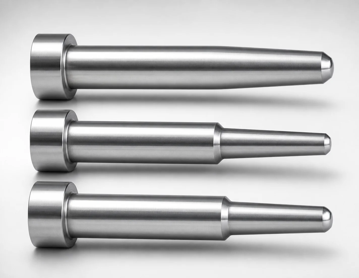
JIS Standard SKH51 Steel One-Step Core Pins - No Second Step
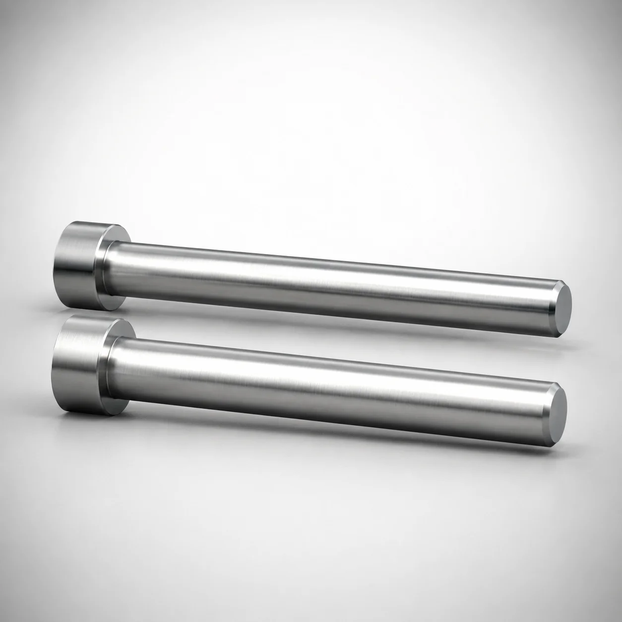
SKH51 Steel Precision Tip Short One-Step Core Pins
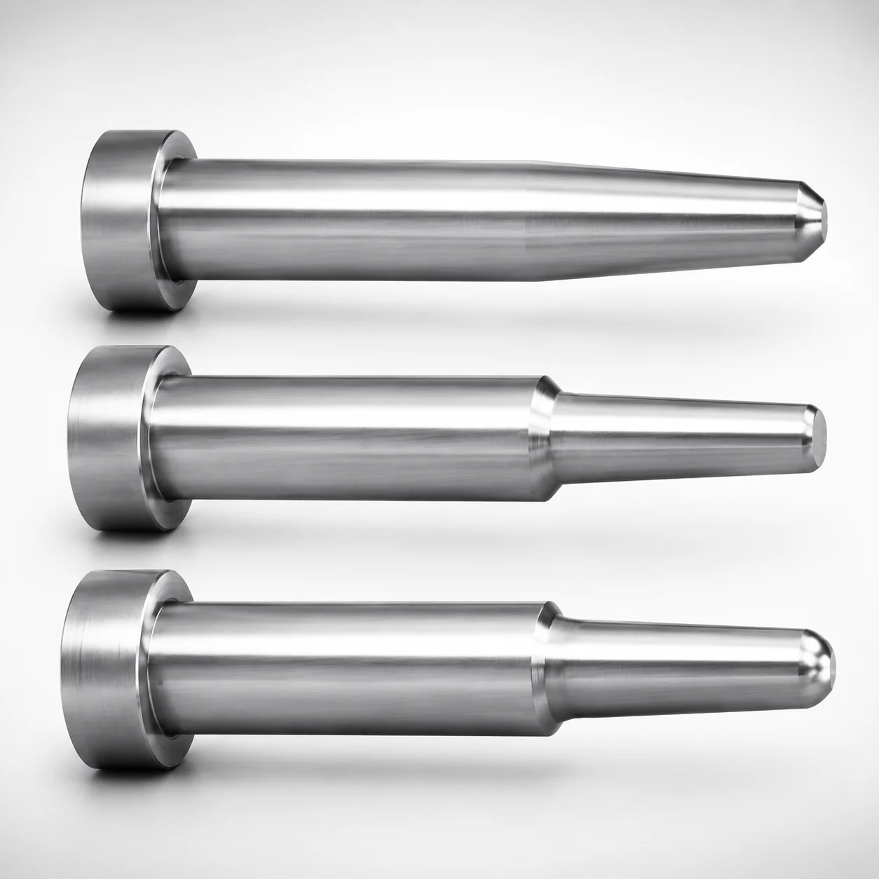
JIS Standard Precision One-Step Core Pins T4 Head
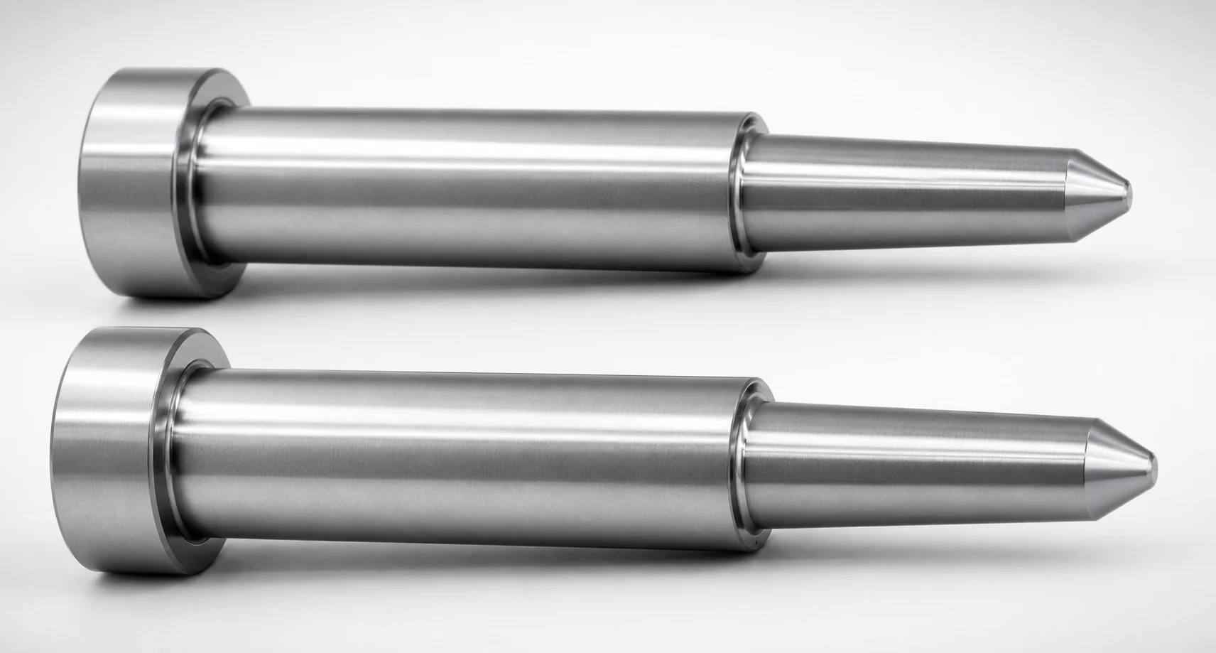
JIS Standard Precision One-Step Core Pins No Second Step
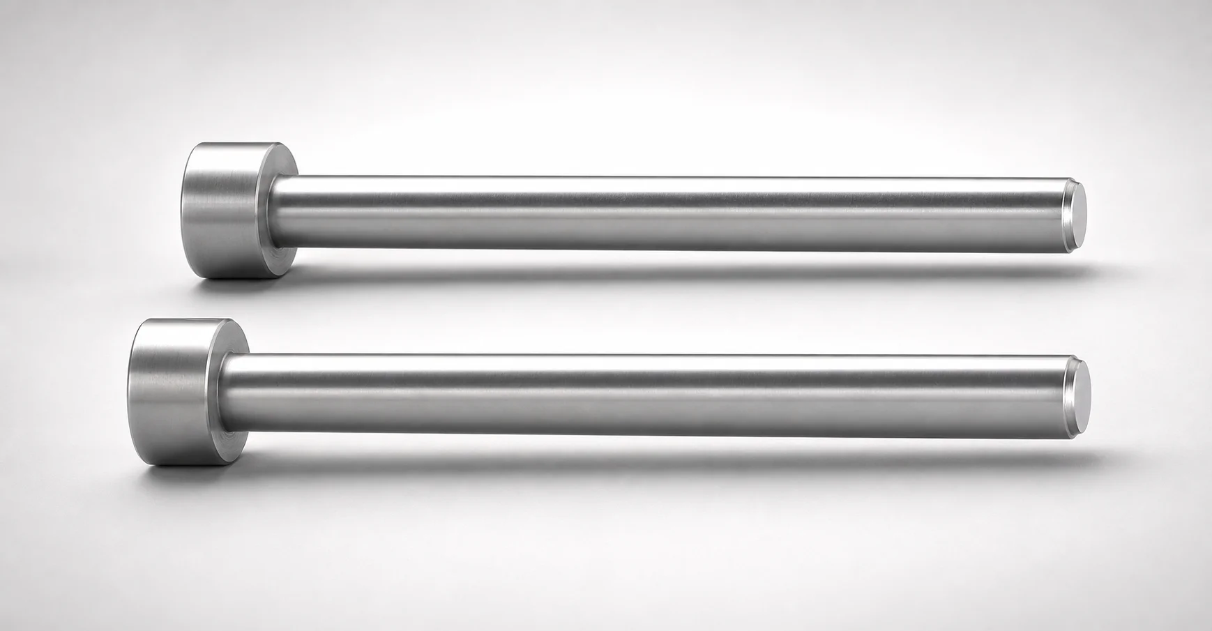
JIS Standard Precision Tip Short One-Step Core Pins
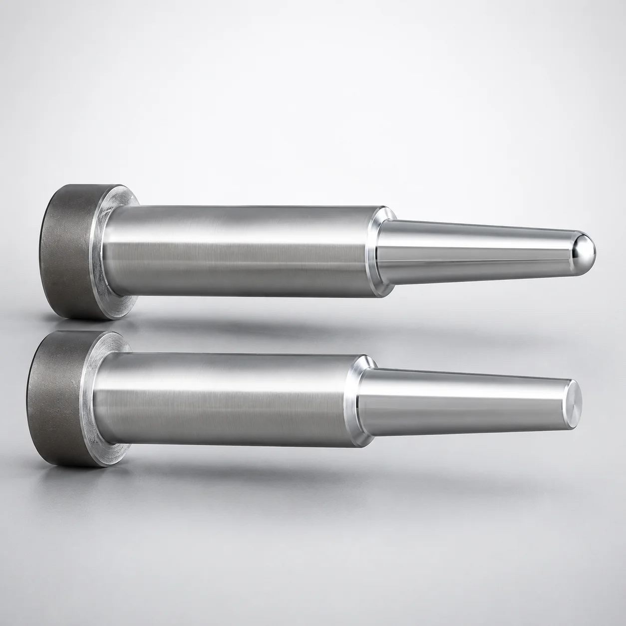
JIS Standard Steel One-Step Core Pins - Tip Lapped
Need Custom Specifications?
Our engineering team can help with custom configurations, material selection, and volume pricing.