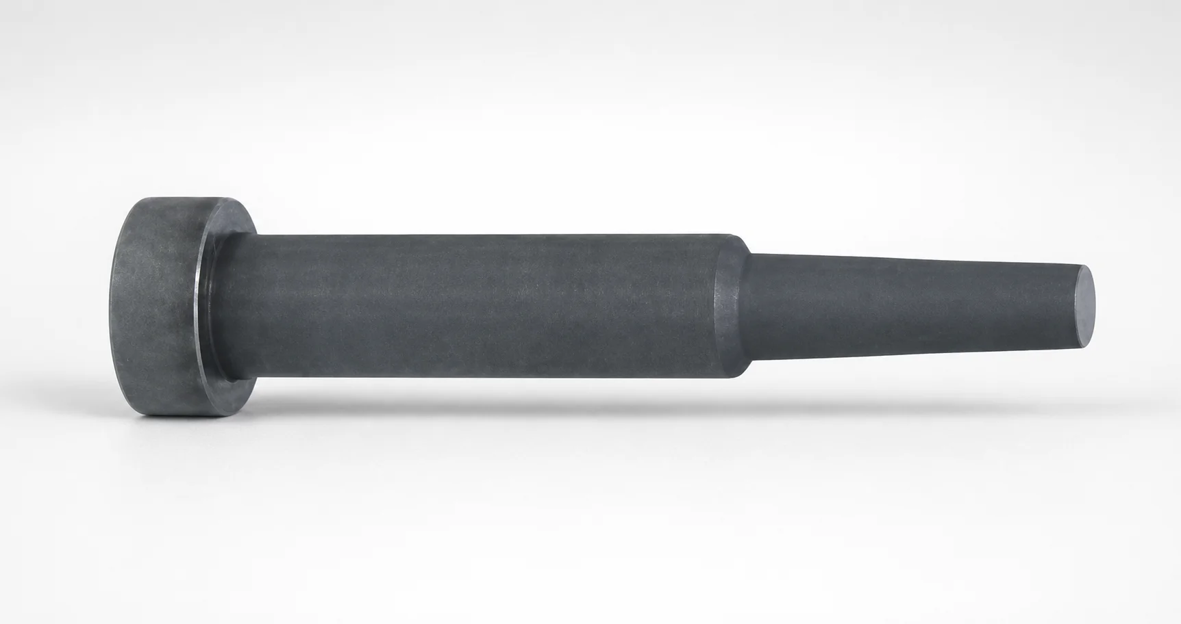
JIS Standard SKD61 Steel One-Step Core Pins
One-step core pins (SKD61 steel) are engineered as a one-piece design with a TiCN-coated tip to support stable positioning and consistent mold operation. The no-second-step geometry reduces variation for reliable ejection alignment in production.
- One-step head design with no second step for consistent core seating and alignment
- SKD61 steel construction with TiCN-coated tip for improved wear resistance
- Selected tolerance references including shaft diameter range and tip gradient ±0.02 support precision mold fitting
- Suitable for precision mold cores and inserts requiring controlled tip geometry during assembly
Specifications
846 configurations available
| L Dimension Tolerance | D/P (Shaft Diameter) (mm) | First Step Shape | Tip Shape | No. (Nominal diameter) (mm) | RE (R shape alteration・enlargement) (mm) | A (Step shape diameter) (mm) | C (Step type taper width) (mm) | CVC (Designation of C dimension in increments of 0.01mm) (mm) | F (Bearing bore length) (mm) | G (Tip C chamfering width) (mm) | K (Tip angle) (°) | L (L dimension) (mm) | Q (Tip R chamfering) (mm) | R (Step type R) (mm) | S (Tip tapered width) (mm) | V (Tip diameter) (mm) | VC (V dimension alteration, smaller than V min) (mm) | type |
|---|---|---|---|---|---|---|---|---|---|---|---|---|---|---|---|---|---|---|
| +0.02/0 | 3 ~ 3.49 | 1A | No processing | 3.5 | - | - | - | - | 10 ~ 119.5 | - | - | 12 ~ 120 | - | - | - | 1 ~ 15.98 | - | - |
| +0.02/0 | 3.5 ~ 3.99 | 1A | No processing | 4 | - | - | - | - | 10 ~ 119.5 | - | - | 12 ~ 120 | - | - | - | 1 ~ 3.98 | - | - |
| +0.02/0 | 4 ~ 4.49 | 1A | No processing | 4.5 | - | - | - | - | 10 ~ 119.5 | - | - | 12 ~ 120 | - | - | - | 1 ~ 4.48 | - | - |
| +0.02/0 | 4.5 ~ 4.99 | 1A | No processing | 5 | - | - | - | - | 10 ~ 119.5 | - | - | 12 ~ 120 | - | - | - | 1 ~ 4.98 | - | - |
| +0.02/0 | 5 ~ 5.49 | 1A | No processing | 5.5 | - | - | - | - | 10 ~ 119.5 | - | - | 12 ~ 120 | - | - | - | 1.5 ~ 5.48 | - | - |
| +0.02/0 | 5 ~ 5.49 | 1A | No processing | 5.5 | - | - | - | - | 10 ~ 119.5 | - | - | 12 ~ 120 | - | - | - | - | 1 ~ 1.49 | - |
| +0.02/0 | 5.5 ~ 5.99 | 1A | No processing | 6 | - | - | - | - | 10 ~ 119.5 | - | - | 12 ~ 120 | - | - | - | 2 ~ 5.98 | - | - |
| +0.02/0 | 5.5 ~ 5.99 | 1A | No processing | 6 | - | - | - | - | 10 ~ 119.5 | - | - | 12 ~ 120 | - | - | - | - | 1.5 ~ 1.99 | - |
| +0.02/0 | 6 ~ 6.49 | 1A | No processing | 6.5 | - | - | - | - | 10 ~ 119.5 | - | - | 12 ~ 120 | - | - | - | 2 ~ 6.48 | - | - |
| +0.02/0 | 6 ~ 6.49 | 1A | No processing | 6.5 | - | - | - | - | 10 ~ 119.5 | - | - | 12 ~ 120 | - | - | - | - | 1.5 ~ 1.99 | - |
| +0.02/0 | 6.5 ~ 6.99 | 1A | No processing | 7 | - | - | - | - | 10 ~ 119.5 | - | - | 12 ~ 120 | - | - | - | 2 ~ 6.98 | - | - |
| +0.02/0 | 6.5 ~ 6.99 | 1A | No processing | 7 | - | - | - | - | 10 ~ 119.5 | - | - | 12 ~ 120 | - | - | - | - | 1.5 ~ 1.99 | - |
| +0.02/0 | 7 ~ 7.99 | 1A | No processing | 8 | - | - | - | - | 10 ~ 119.5 | - | - | 12 ~ 120 | - | - | - | 2 ~ 7.98 | - | - |
| +0.02/0 | 7 ~ 7.99 | 1A | No processing | 8 | - | - | - | - | 10 ~ 119.5 | - | - | 12 ~ 120 | - | - | - | - | 1.5 ~ 1.99 | - |
| +0.02/0 | 8 ~ 9.99 | 1A | No processing | 10 | - | - | - | - | 10 ~ 119.5 | - | - | 12 ~ 120 | - | - | - | 2 ~ 9.98 | - | - |
| +0.02/0 | 8 ~ 9.99 | 1A | No processing | 10 | - | - | - | - | 10 ~ 119.5 | - | - | 12 ~ 120 | - | - | - | - | 1.5 ~ 1.99 | - |
| +0.02/0 | 10 ~ 12.99 | 1A | No processing | 13 | - | - | - | - | 10 ~ 119.5 | - | - | 12 ~ 120 | - | - | - | 2 ~ 12.98 | - | - |
| +0.02/0 | 13 ~ 15.99 | 1A | No processing | 16 | - | - | - | - | 10 ~ 119.5 | - | - | 12 ~ 120 | - | - | - | 2 ~ 15.98 | - | - |
| +0.02/0 | 16 ~ 19.99 | 1A | No processing | 20 | - | - | - | - | 28 ~ 119.5 | - | - | 30 ~ 120 | - | - | - | 5 ~ 19.99 | - | - |
| +0.02/0 | 16 ~ 19.99 | 1A | No processing | 20 | - | - | - | - | 28 ~ 119.5 | - | - | 30 ~ 120 | - | - | - | - | 4 ~ 4.99 | - |
| 0/-0.1 | 3 ~ 3.49 | 1A | B | 3.5 | - | - | - | - | 10 ~ 119.5 | - | - | 12 ~ 120 | - | - | - | 1 ~ 3.48 | - | - |
| 0/-0.1 | 3.5 ~ 3.99 | 1A | B | 4 | - | - | - | - | 10 ~ 119.5 | - | - | 12 ~ 120 | - | - | - | 1 ~ 3.98 | - | - |
| 0/-0.1 | 4 ~ 4.49 | 1A | B | 4.5 | - | - | - | - | 10 ~ 119.5 | - | - | 12 ~ 120 | - | - | - | 1 ~ 4.48 | - | - |
| 0/-0.1 | 4.5 ~ 4.99 | 1A | B | 5 | - | - | - | - | 10 ~ 119.5 | - | - | 12 ~ 120 | - | - | - | 1 ~ 4.98 | - | - |
| 0/-0.1 | 5 ~ 5.49 | 1A | B | 5.5 | - | - | - | - | 10 ~ 119.5 | - | - | 12 ~ 120 | - | - | - | 1.5 ~ 5.48 | - | - |
| 0/-0.1 | 5 ~ 5.49 | 1A | B | 5.5 | - | - | - | - | 10 ~ 119.5 | - | - | 12 ~ 120 | - | - | - | - | 1 ~ 1.49 | - |
| 0/-0.1 | 5.5 ~ 5.99 | 1A | B | 6 | - | - | - | - | 10 ~ 119.5 | - | - | 12 ~ 120 | - | - | - | 2 ~ 5.98 | - | - |
| 0/-0.1 | 5.5 ~ 5.99 | 1A | B | 6 | - | - | - | - | 10 ~ 119.5 | - | - | 12 ~ 120 | - | - | - | - | 1.5 ~ 1.99 | - |
| 0/-0.1 | 6 ~ 6.49 | 1A | B | 6.5 | - | - | - | - | 10 ~ 119.5 | - | - | 12 ~ 120 | - | - | - | 2 ~ 6.48 | - | - |
| 0/-0.1 | 6 ~ 6.49 | 1A | B | 6.5 | - | - | - | - | 10 ~ 119.5 | - | - | 12 ~ 120 | - | - | - | - | 1.5 ~ 1.99 | - |
| 0/-0.1 | 6.5 ~ 6.99 | 1A | B | 7 | - | - | - | - | 10 ~ 119.5 | - | - | 12 ~ 120 | - | - | - | 2 ~ 6.98 | - | - |
| 0/-0.1 | 6.5 ~ 6.99 | 1A | B | 7 | - | - | - | - | 10 ~ 119.5 | - | - | 12 ~ 120 | - | - | - | - | 1.5 ~ 1.99 | - |
| 0/-0.1 | 7 ~ 7.99 | 1A | B | 8 | - | - | - | - | 10 ~ 119.5 | - | - | 12 ~ 120 | - | - | - | 2 ~ 7.98 | - | - |
| 0/-0.1 | 7 ~ 7.99 | 1A | B | 8 | - | - | - | - | 10 ~ 119.5 | - | - | 12 ~ 120 | - | - | - | - | 1.5 ~ 1.99 | - |
| 0/-0.1 | 8 ~ 9.99 | 1A | B | 10 | - | - | - | - | 10 ~ 119.5 | - | - | 12 ~ 120 | - | - | - | 2 ~ 9.98 | - | - |
| 0/-0.1 | 8 ~ 9.99 | 1A | B | 10 | - | - | - | - | 10 ~ 119.5 | - | - | 12 ~ 120 | - | - | - | - | 1.5 ~ 1.99 | - |
| 0/-0.1 | 10 ~ 12.99 | 1A | B | 13 | - | - | - | - | 10 ~ 119.5 | - | - | 12 ~ 120 | - | - | - | 2 ~ 12.98 | - | - |
| 0/-0.1 | 13 ~ 15.99 | 1A | B | 16 | - | - | - | - | 10 ~ 119.5 | - | - | 12 ~ 120 | - | - | - | 2 ~ 15.98 | - | - |
| 0/-0.1 | 16 ~ 19.99 | 1A | B | 20 | - | - | - | - | 28 ~ 119.5 | - | - | 30 ~ 120 | - | - | - | 5 ~ 19.99 | - | - |
| 0/-0.1 | 16 ~ 19.99 | 1A | B | 20 | - | - | - | - | 28 ~ 119.5 | - | - | 30 ~ 120 | - | - | - | - | 4 ~ 4.99 | - |
| +0.02/0 | 3 ~ 3.49 | 1A | C | 3.5 | - | - | - | - | 10 ~ 119.5 | 0.5 ~ 1.7 | - | 12 ~ 120 | - | - | - | 1 ~ 3.48 | - | - |
| +0.02/0 | 3.5 ~ 3.99 | 1A | C | 4 | - | - | - | - | 10 ~ 119.5 | 0.5 ~ 1.9 | - | 12 ~ 120 | - | - | - | 1 ~ 3.98 | - | - |
| +0.02/0 | 4 ~ 4.49 | 1A | C | 4.5 | - | - | - | - | 10 ~ 119.5 | 0.5 ~ 2.2 | - | 12 ~ 120 | - | - | - | 1 ~ 4.48 | - | - |
| +0.02/0 | 4.5 ~ 4.99 | 1A | C | 5 | - | - | - | - | 10 ~ 119.5 | 0.5 ~ 2.4 | - | 12 ~ 120 | - | - | - | 1 ~ 4.98 | - | - |
| +0.02/0 | 5 ~ 5.49 | 1A | C | 5.5 | - | - | - | - | 10 ~ 119.5 | 0.5 ~ 2.7 | - | 12 ~ 120 | - | - | - | 1.5 ~ 5.48 | - | - |
| +0.02/0 | 5 ~ 5.49 | 1A | C | 5.5 | - | - | - | - | 10 ~ 119.5 | 0.5 ~ 2.7 | - | 12 ~ 120 | - | - | - | - | 1 ~ 1.49 | - |
| +0.02/0 | 5.5 ~ 5.99 | 1A | C | 6 | - | - | - | - | 10 ~ 119.5 | 0.5 ~ 2.9 | - | 12 ~ 120 | - | - | - | 2 ~ 5.98 | - | - |
| +0.02/0 | 5.5 ~ 5.99 | 1A | C | 6 | - | - | - | - | 10 ~ 119.5 | 0.5 ~ 2.9 | - | 12 ~ 120 | - | - | - | - | 1.5 ~ 1.99 | - |
| +0.02/0 | 6 ~ 6.49 | 1A | C | 6.5 | - | - | - | - | 10 ~ 119.5 | 0.5 ~ 3.2 | - | 12 ~ 120 | - | - | - | 2 ~ 6.48 | - | - |
| +0.02/0 | 6 ~ 6.49 | 1A | C | 6.5 | - | - | - | - | 10 ~ 119.5 | 0.5 ~ 3.2 | - | 12 ~ 120 | - | - | - | - | 1.5 ~ 1.99 | - |
Product Guide
Application Scenarios+
One-step core pins are used in injection mold toolsets where precise alignment and repeatable ejection paths are critical. Their single, no-second-step head design helps maintain stable core seating during mold closure, reducing variation that can otherwise shift the ejector alignment over production cycles.
- Automotive connector and housing molds: The TiCN-coated tip supports wear-resistant guidance under repeated spotting and ejection, helping keep tight fit between stepped core features and mating components.
- Precision consumer electronics housings: The controlled tip geometry and tight dimensioning ranges (including tip gradient ±0.02) support accurate assembly and consistent core positioning for fine wall/feature tolerances.
- Medical device component molds: One-piece core pin construction minimizes step-to-step stack-up, supporting reliable registration when multiple inserts or cores must stay aligned during thermal cycling.
Material & Process Details+
This variant uses JIS Standard SKD61 steel for the core pin body. SKD61 is commonly mapped to an H13-class hot-work tool steel, providing a practical balance of hardness, toughness, and thermal fatigue performance for cyclic molding environments.
- TiCN-coated tip: The TiCN surface is intended to improve wear resistance at the guiding tip where sliding contact and repeated alignment loads are highest.
- Heat treatment: Supplied parts are typically produced from quenched & tempered SKD61 or pre-hardened stock depending on the manufacturer’s workflow, followed by coating for the tip (exact hardness/HRC is not specified in the provided data).
- Trade-offs: Higher hardness improves wear life but can reduce toughness; SKD61’s tempered structure is selected to maintain impact resistance under repeated mold opening/closing.
Sizing & Selection Guide+
Select the core pin by matching both the shaft diameter range and the stepped geometry to the core insert and mating bore. The D/P (shaft diameter) is available from 3 ~ 16 mm, and the nominal diameter range No. (3.5 ~ 20 mm) should align with your design’s callout.
- Length (L): Choose from 12 ~ 120 mm (with an alternate range of 30 ~ 120 mm per the listed specification) to suit the required engagement depth in the mold block.
- Tip and step geometry: Set the first step shape (1A ~ 1E) and tip shape (No processing, B, C, G, R, T) to control guidance and ejection alignment. Step type parameters include A = 1 ~ 4 mm, and taper width options such as C = 0.1 ~ 4 mm (or 0.1 ~ 3.9, 1.1 ~ 4 depending on the configuration).
- Tolerance & fit: The L dimension tolerance is listed as +0.02/0, 0/-0.1. Use this tolerance to verify clearance/press-fit expectations for the bearing bore length F = 10 ~ 28 mm and to prevent misalignment from stack-up.
Frequently Asked Questions
Which SKD61 core pin dimensions should I verify first for stepped core alignment?+
How does the one-step (no-second-step) design affect mold core seating and ejection alignment?+
What does the listed L dimension tolerance mean for assembly clearance?+
What role does the TiCN-coated tip play, and which tip options are available?+
How do I choose tip/step geometry parameters like C, K, and step R to meet tight positioning requirements?+
Related Products
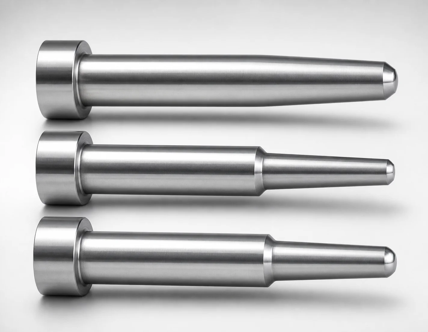
JIS Standard SKH51 Steel One-Step Core Pins - No Second Step
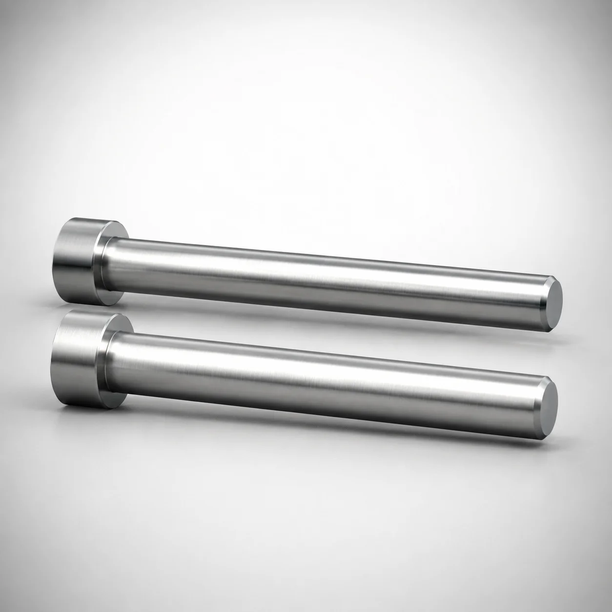
SKH51 Steel Precision Tip Short One-Step Core Pins
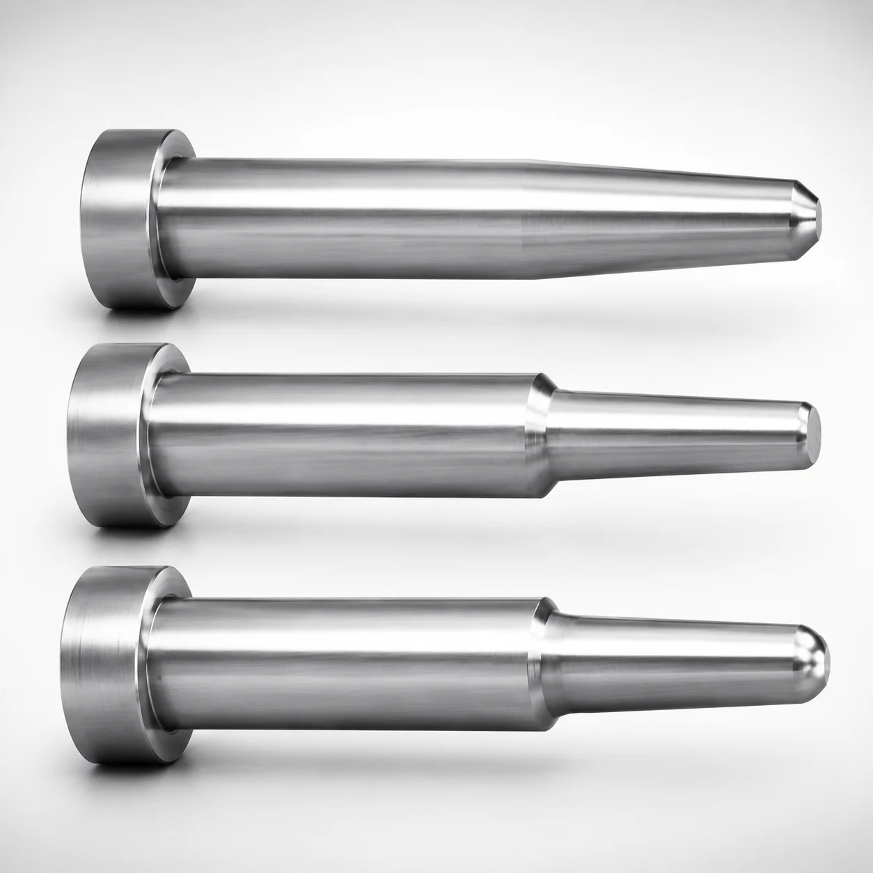
JIS Standard Precision One-Step Core Pins T4 Head
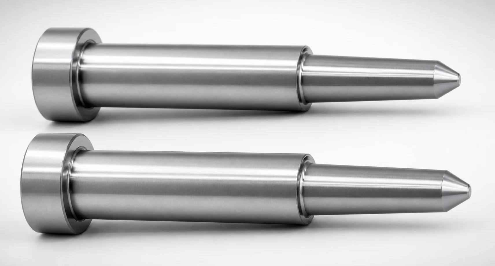
JIS Standard Precision One-Step Core Pins No Second Step
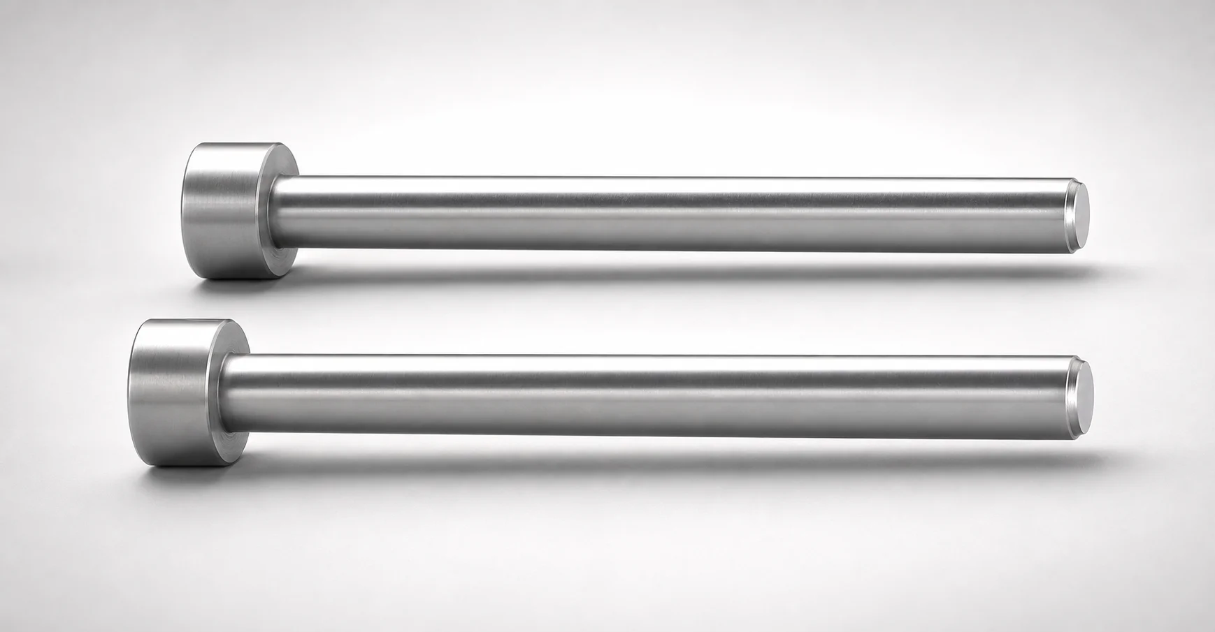
JIS Standard Precision Tip Short One-Step Core Pins
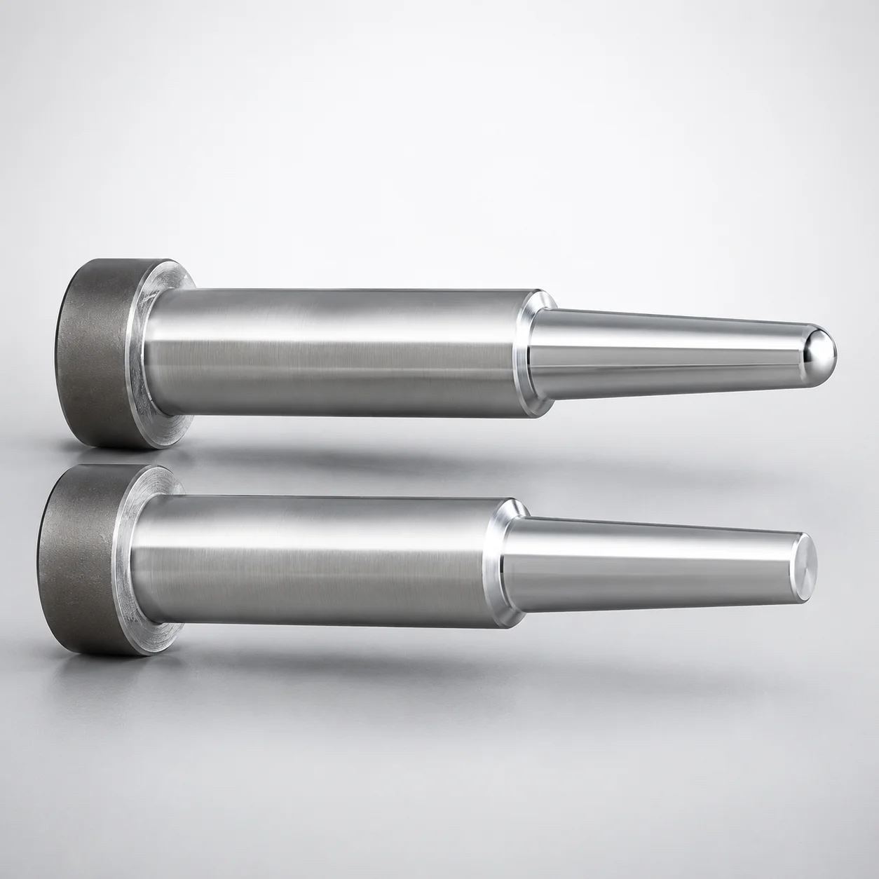
JIS Standard Steel One-Step Core Pins - Tip Lapped
Need Custom Specifications?
Our engineering team can help with custom configurations, material selection, and volume pricing.