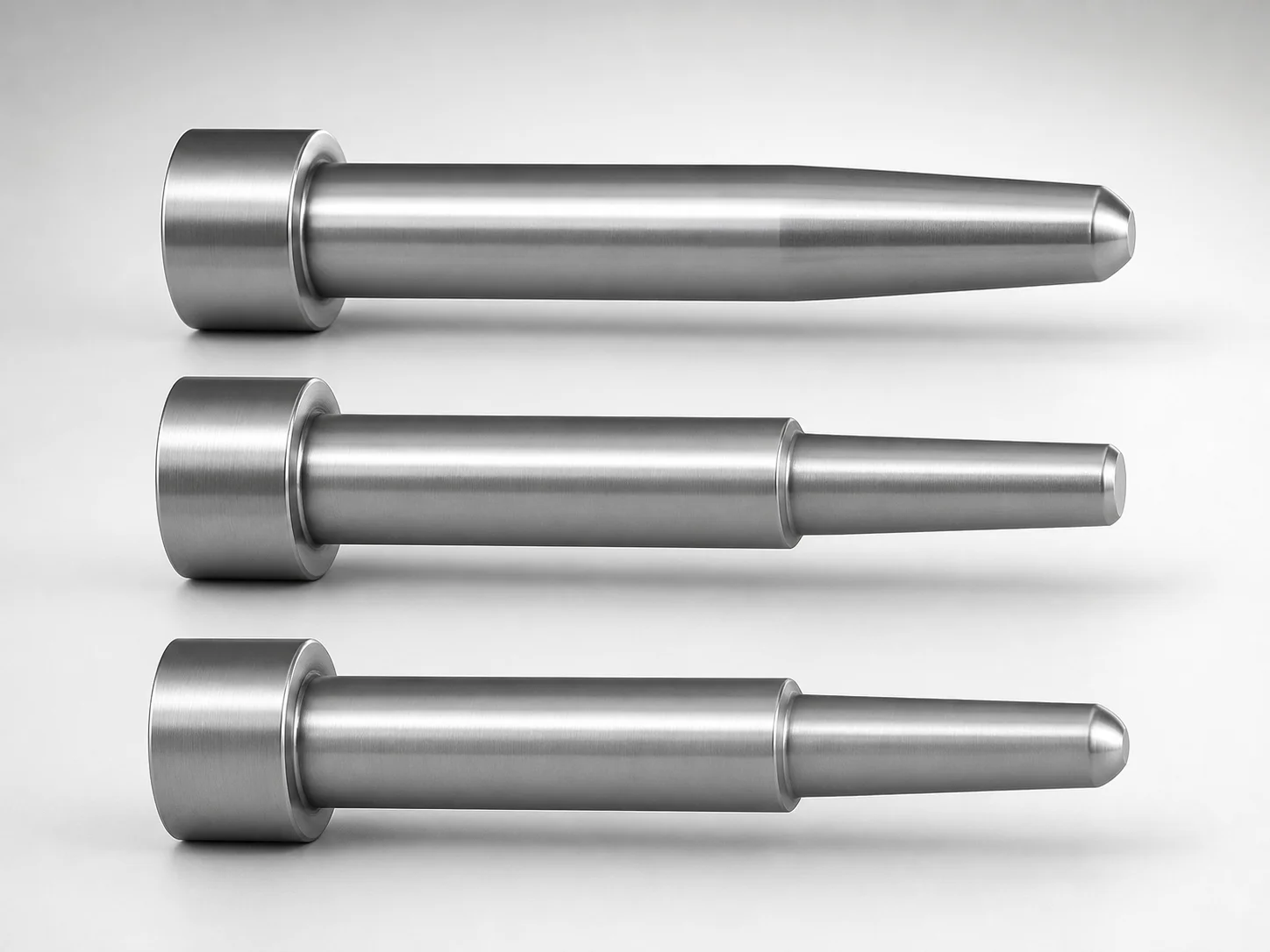
JIS Standard SKD61 Steel One-Step Core Pins
One-Step Core Pins (SKD61 steel) with a no second step shape provide stable positioning for mold locating and efficient assembly. The core pin design supports tight workpiece fit through controlled shaft geometry and tip finish consistency.
- One-step profile with no second step reduces locating variation during mold closure
- SKD61 steel construction with hardened wear performance for long production runs
- Shaft diameter tolerances of -0.01/-0.02 supports accurate alignment in bushings
- JIS standard compatibility suitable for core/cavity mold applications
Specifications
1049 configurations available
| L Dimension Tolerance | Head Thickness | D/P (Shaft Diameter) (mm) | First Step Shape | Tip Shape | No. (Nominal diameter) (mm) | RE (R shape alteration・enlargement) (mm) | A (Step shape diameter) (mm) | C (Step type taper width) (mm) | CVC (Designation of C dimension in increments of 0.01mm) (mm) | F (Bearing bore length) (mm) | G (Tip C chamfering width) (mm) | K (Tip angle) (°) | L (L dimension) (mm) | Q (Tip R chamfering) (mm) | R (Step type R) (mm) | S (Tip tapered width) (mm) | V (Tip diameter) (mm) | VC (V dimension alteration (mm) | type |
|---|---|---|---|---|---|---|---|---|---|---|---|---|---|---|---|---|---|---|---|
| +0.02/0 | 6mm(JIS) | 4 | 1A | No processing | - | - | - | - | - | 30 ~ 119.5 | - | - | 40 ~ 120 | - | - | - | 1 ~ 3.99 | - | - |
| +0.02/0 | 6mm(JIS) | 4 | 1A | No processing | - | - | - | - | - | 30 ~ 119.5 | - | - | 40 ~ 120 | - | - | - | - | 0.7 ~ 0.99 | - |
| +0.02/0 | 6mm(JIS) | 4.5 | 1A | No processing | - | - | - | - | - | 30 ~ 119.5 | - | - | 40 ~ 120 | - | - | - | 1 ~ 4.49 | - | - |
| +0.02/0 | 6mm(JIS) | 5 | 1A | No processing | - | - | - | - | - | 30 ~ 119.5 | - | - | 40 ~ 120 | - | - | - | 1 ~ 4.99 | - | - |
| +0.02/0 | 6mm(JIS) | 5.5 | 1A | No processing | - | - | - | - | - | 30 ~ 119.5 | - | - | 40 ~ 120 | - | - | - | 1.5 ~ 5.49 | - | - |
| +0.02/0 | 6mm(JIS) | 5.5 | 1A | No processing | - | - | - | - | - | 30 ~ 119.5 | - | - | 40 ~ 120 | - | - | - | - | 1 ~ 1.49 | - |
| +0.02/0 | 6mm(JIS) | 6 | 1A | No processing | - | - | - | - | - | 30 ~ 119.5 | - | - | 40 ~ 120 | - | - | - | 2 ~ 5.99 | - | - |
| +0.02/0 | 6mm(JIS) | 6 | 1A | No processing | - | - | - | - | - | 30 ~ 119.5 | - | - | 40 ~ 120 | - | - | - | - | 1.5 ~ 1.99 | - |
| +0.02/0 | 6mm(JIS) | 6.5 | 1A | No processing | - | - | - | - | - | 30 ~ 119.5 | - | - | 40 ~ 120 | - | - | - | 2 ~ 6.49 | - | - |
| +0.02/0 | 6mm(JIS) | 6.5 | 1A | No processing | - | - | - | - | - | 30 ~ 119.5 | - | - | 40 ~ 120 | - | - | - | - | 1.5 ~ 1.99 | - |
| +0.02/0 | 6mm(JIS) | 7 | 1A | No processing | - | - | - | - | - | 30 ~ 119.5 | - | - | 40 ~ 120 | - | - | - | 2 ~ 6.99 | - | - |
| +0.02/0 | 6mm(JIS) | 7 | 1A | No processing | - | - | - | - | - | 30 ~ 119.5 | - | - | 40 ~ 120 | - | - | - | - | 1.5 ~ 1.99 | - |
| +0.02/0 | 8mm(JIS) | 8 | 1A | No processing | - | - | - | - | - | 30 ~ 119.5 | - | - | 40 ~ 120 | - | - | - | 2 ~ 7.99 | - | - |
| +0.02/0 | 8mm(JIS) | 8 | 1A | No processing | - | - | - | - | - | 30 ~ 119.5 | - | - | 40 ~ 120 | - | - | - | - | 1.5 ~ 1.99 | - |
| +0.02/0 | 8mm(JIS) | 10 | 1A | No processing | - | - | - | - | - | 30 ~ 119.5 | - | - | 40 ~ 120 | - | - | - | 2 ~ 9.99 | - | - |
| +0.02/0 | 8mm(JIS) | 10 | 1A | No processing | - | - | - | - | - | 30 ~ 119.5 | - | - | 40 ~ 120 | - | - | - | - | 1.5 ~ 1.99 | - |
| 0/-0.1 | 6mm(JIS) | 4 | 1A | B | - | - | - | - | - | 30 ~ 119.5 | - | - | 40 ~ 120 | - | - | - | 1 ~ 3.99 | - | - |
| 0/-0.1 | 6mm(JIS) | 4 | 1A | B | - | - | - | - | - | 30 ~ 119.5 | - | - | 40 ~ 120 | - | - | - | - | 0.7 ~ 0.99 | - |
| 0/-0.1 | 6mm(JIS) | 4.5 | 1A | B | - | - | - | - | - | 30 ~ 119.7 | - | - | 40 ~ 120 | - | - | - | 1 ~ 4.49 | - | - |
| 0/-0.1 | 6mm(JIS) | 5 | 1A | B | - | - | - | - | - | 30 ~ 119.5 | - | - | 40 ~ 120 | - | - | - | 1 ~ 4.99 | - | - |
| 0/-0.1 | 6mm(JIS) | 5.5 | 1A | B | - | - | - | - | - | 30 ~ 119.7 | - | - | 40 ~ 120 | - | - | - | 1.5 ~ 5.49 | - | - |
| 0/-0.1 | 6mm(JIS) | 5.5 | 1A | B | - | - | - | - | - | 30 ~ 119.7 | - | - | 40 ~ 120 | - | - | - | - | 1 ~ 1.49 | - |
| 0/-0.1 | 6mm(JIS) | 6 | 1A | B | - | - | - | - | - | 30 ~ 119.5 | - | - | 40 ~ 120 | - | - | - | 2 ~ 5.99 | - | - |
| 0/-0.1 | 6mm(JIS) | 6 | 1A | B | - | - | - | - | - | 30 ~ 119.5 | - | - | 40 ~ 120 | - | - | - | - | 1.5 ~ 1.99 | - |
| 0/-0.1 | 6mm(JIS) | 6.5 | 1A | B | - | - | - | - | - | 30 ~ 119.7 | - | - | 40 ~ 120 | - | - | - | 2 ~ 6.49 | - | - |
| 0/-0.1 | 6mm(JIS) | 6.5 | 1A | B | - | - | - | - | - | 30 ~ 119.7 | - | - | 40 ~ 120 | - | - | - | - | 1.5 ~ 1.99 | - |
| 0/-0.1 | 6mm(JIS) | 7 | 1A | B | - | - | - | - | - | 30 ~ 119.7 | - | - | 40 ~ 120 | - | - | - | 2 ~ 6.99 | - | - |
| 0/-0.1 | 6mm(JIS) | 7 | 1A | B | - | - | - | - | - | 30 ~ 119.7 | - | - | 40 ~ 120 | - | - | - | - | 1.5 ~ 1.99 | - |
| 0/-0.1 | 8mm(JIS) | 8 | 1A | B | - | - | - | - | - | 30 ~ 119.5 | - | - | 40 ~ 120 | - | - | - | 2 ~ 7.99 | - | - |
| 0/-0.1 | 8mm(JIS) | 8 | 1A | B | - | - | - | - | - | 30 ~ 119.5 | - | - | 40 ~ 120 | - | - | - | - | 1.5 ~ 1.99 | - |
| 0/-0.1 | 8mm(JIS) | 10 | 1A | B | - | - | - | - | - | 30 ~ 119.5 | - | - | 40 ~ 120 | - | - | - | 2 ~ 9.99 | - | - |
| 0/-0.1 | 8mm(JIS) | 10 | 1A | B | - | - | - | - | - | 30 ~ 119.5 | - | - | 40 ~ 120 | - | - | - | - | 1.5 ~ 1.99 | - |
| +0.02/0 | 6mm(JIS) | 4 | 1A | C | - | - | - | - | - | 30 ~ 119 | 0.5 ~ 1.9 | - | 40 ~ 120 | - | - | - | 1 ~ 3.99 | - | - |
| +0.02/0 | 6mm(JIS) | 4 | 1A | C | - | - | - | - | - | 30 ~ 119 | 0.5 ~ 1.9 | - | 40 ~ 120 | - | - | - | - | 0.7 ~ 0.99 | - |
| +0.02/0 | 6mm(JIS) | 4.5 | 1A | C | - | - | - | - | - | 30 ~ 119.7 | 0.5 ~ 2.2 | - | 40 ~ 120 | - | - | - | 1 ~ 4.49 | - | - |
| +0.02/0 | 6mm(JIS) | 5 | 1A | C | - | - | - | - | - | 30 ~ 119 | 0.5 ~ 2.4 | - | 40 ~ 120 | - | - | - | 1 ~ 4.99 | - | - |
| +0.02/0 | 6mm(JIS) | 5.5 | 1A | C | - | - | - | - | - | 30 ~ 119.7 | 0.5 ~ 2.7 | - | 40 ~ 120 | - | - | - | 1.5 ~ 5.49 | - | - |
| +0.02/0 | 6mm(JIS) | 5.5 | 1A | C | - | - | - | - | - | 30 ~ 119.7 | 0.5 ~ 2.7 | - | 40 ~ 120 | - | - | - | - | 1 ~ 1.49 | - |
| +0.02/0 | 6mm(JIS) | 6 | 1A | C | - | - | - | - | - | 30 ~ 119 | 0.5 ~ 2.9 | - | 40 ~ 120 | - | - | - | 2 ~ 5.99 | - | - |
| +0.02/0 | 6mm(JIS) | 6 | 1A | C | - | - | - | - | - | 30 ~ 119 | 0.5 ~ 2.9 | - | 40 ~ 120 | - | - | - | - | 1.5 ~ 1.99 | - |
| +0.02/0 | 6mm(JIS) | 6.5 | 1A | C | - | - | - | - | - | 30 ~ 119.7 | 0.5 ~ 3.2 | - | 40 ~ 120 | - | - | - | 2 ~ 6.49 | - | - |
| +0.02/0 | 6mm(JIS) | 6.5 | 1A | C | - | - | - | - | - | 30 ~ 119.7 | 0.5 ~ 3.2 | - | 40 ~ 120 | - | - | - | - | 1.5 ~ 1.99 | - |
| +0.02/0 | 6mm(JIS) | 7 | 1A | C | - | - | - | - | - | 30 ~ 119.5 | 0.5 ~ 3.4 | - | 40 ~ 120 | - | - | - | 2 ~ 6.99 | - | - |
| +0.02/0 | 6mm(JIS) | 7 | 1A | C | - | - | - | - | - | 30 ~ 119.5 | 0.5 ~ 3.4 | - | 40 ~ 120 | - | - | - | - | 1.5 ~ 1.99 | - |
| +0.02/0 | 8mm(JIS) | 8 | 1A | C | - | - | - | - | - | 30 ~ 119 | 0.5 ~ 3.9 | - | 40 ~ 120 | - | - | - | 2 ~ 7.99 | - | - |
| +0.02/0 | 8mm(JIS) | 8 | 1A | C | - | - | - | - | - | 30 ~ 119 | 0.5 ~ 3.9 | - | 40 ~ 120 | - | - | - | - | 1.5 ~ 1.99 | - |
| +0.02/0 | 8mm(JIS) | 10 | 1A | C | - | - | - | - | - | 30 ~ 119 | 0.5 ~ 4.9 | - | 40 ~ 120 | - | - | - | 2 ~ 9.99 | - | - |
| +0.02/0 | 8mm(JIS) | 10 | 1A | C | - | - | - | - | - | 30 ~ 119 | 0.5 ~ 4.9 | - | 40 ~ 120 | - | - | - | - | 1.5 ~ 1.99 | - |
| 0/-0.1 | 6mm(JIS) | 4 | 1A | G | - | - | - | - | - | 30 ~ 119.5 | - | 21 ~ 60 | 40 ~ 120 | - | - | - | 1 ~ 3.99 | - | - |
| 0/-0.1 | 6mm(JIS) | 4 | 1A | G | - | - | - | - | - | 30 ~ 119.5 | - | 21 ~ 60 | 40 ~ 120 | - | - | - | - | 0.7 ~ 0.99 | - |
Product Guide
Application Scenarios+
This one-step core pin is designed for precise locating in core/cavity mold assemblies where stable alignment during mold closure is critical. Its no second step geometry helps reduce locating variation across repeated cycles, improving part-to-part positional consistency.
- Automotive connector and sensor housings: Use the controlled shaft geometry to maintain concentricity in locating holes, supporting tight fit between core pin and mating bushings/bores for accurate insert alignment.
- Consumer electronics enclosures: The consistent tip finish options and SKD61 wear-oriented construction help resist dimension drift in high-shot production, supporting stable gate and feature locations.
- Medical device component molds: Reliable locating supports repeatable features that depend on core-pin positioning; select appropriate tip shape (e.g., B/C/G/R/T) to match the cavity entrance profile.
Shaft diameter variants in D/P 3.5–10 mm with tight tolerance (-0.01/-0.02) make this pin suitable for applications that require predictable clearance/fit with bushings.
Material & Process Details+
JIS Standard SKD61 tool steel (commonly associated with H13-type hot-work mold steels) is selected for its balance of hardness and toughness in cyclic molding conditions. For core locating pins, wear resistance and dimensional stability are prioritized under repeated contact and sliding during mold open/close.
- Heat treatment: Typically supplied and used in a quenched & tempered condition to reach service hardness appropriate for tooling applications (final hardness is application-dependent).
- Hardness & wear: SKD61 is capable of high hardness for improved wear performance, supporting long production runs where locating surfaces experience repeated load.
- Toughness trade-off: Increasing hardness can reduce impact toughness; quenched & tempered optimization helps maintain a usable toughness level for core/cavity systems.
- Tip finish options: Different tip shapes (e.g., No processing, B/C/G/R/T) allow you to tune contact behavior without changing the core steel foundation.
If you require higher wear under extreme abrasion, compare with higher-alloy tool steels or nitriding-capable steels; however, this SKD61 option is well aligned with general-purpose durable mold core pin use.
Sizing & Selection Guide+
Choose the core pin size by matching the shaft diameter (D/P) and the overall L to your mold locating bore and core/cavity layout. This variant supports D/P = 3.5–10 mm with nominal diameters of 4, 5, 6, 8, 10 mm, using shaft tolerance of -0.01/-0.02 to support accurate alignment in bushings.
- Length (L): Select L = 40–120 mm to ensure sufficient engagement depth while avoiding interference with adjacent mold components.
- No-second-step profile: Confirm that your bushing/hole system is designed for a single-step locating surface, since the geometry includes no second step and is intended to reduce locating variation.
- Step and tip features: Select the first step shape (1A–1E) and compatible tip shape (No processing, B/C/G/R/T) based on your cavity entrance and the desired centering/contact behavior.
- Tolerance/fit: Use the provided shaft tolerance (-0.01/-0.02) when calculating clearance and press/slide behavior in the mating bore. Account for your bushing tolerance stack when setting functional fit.
Some parameters are configurable (tip shape, step shape, diameters), while L is fixed to 40–120 mm range and the no-second-step feature remains constant for this series.
Frequently Asked Questions
How should I choose the shaft diameter (D/P) for reliable locating in the bushing or bore?+
Select D/P within 3.5–10 mm and use the nominal diameter options (4, 5, 6, 8, 10 mm) supported by this series. The shaft diameter tolerance is specified as -0.01/-0.02, which is intended to support precise alignment with the mating bushing/bore. Confirm your clearance/fit using your bushing tolerance stack, especially if you require a sliding vs. near-interference locating behavior.
What does “no second step” change for core pin locating stability compared with stepped alternatives?+
This design uses a one-step profile with no second step, reducing variation that can occur when closure forces interact with multiple locating surfaces. In practical mold assembly, this helps maintain more consistent positional repeatability at the main locating interface. When selecting, ensure your bushing or locating hole system is compatible with a single-step engagement rather than expecting a second shoulder.
How do I match the pin length (L) to my mold stack height without causing interference?+
Use the fixed L range of 40–120 mm to set the engagement length relative to core/cavity spacing. Verify that the selected L provides sufficient support for the locating function while clearing adjacent components during opening/closing. Because the profile is one-step, confirm that your limiting surfaces are compatible with the no-second-step geometry to avoid unintended contact.
Which tip shape options should I consider for tuning contact at the cavity entrance?+
This series provides multiple tip shapes: No processing, B, C, G, R, and T. The choice should align with your cavity entrance geometry and the centering/contact behavior you want. Additionally, the pin includes fixed tip geometry features such as Q = 0.2 and S = 0.1 ranges, so evaluate tip fit based on your mold layout rather than relying only on the tip label.
What are the key SKD61 material expectations for durability and wear on core locating pins?+
SKD61 is specified as the JIS standard steel for this core pin, selected to provide durable wear performance during repeated mold open/close cycles. The typical tool-steel approach is quenched & tempered heat treatment to achieve service hardness while maintaining usable toughness. If your application is highly abrasive, consider whether additional surface engineering (e.g., nitriding in your process plan) is needed beyond the base SKD61 condition.
Related Products
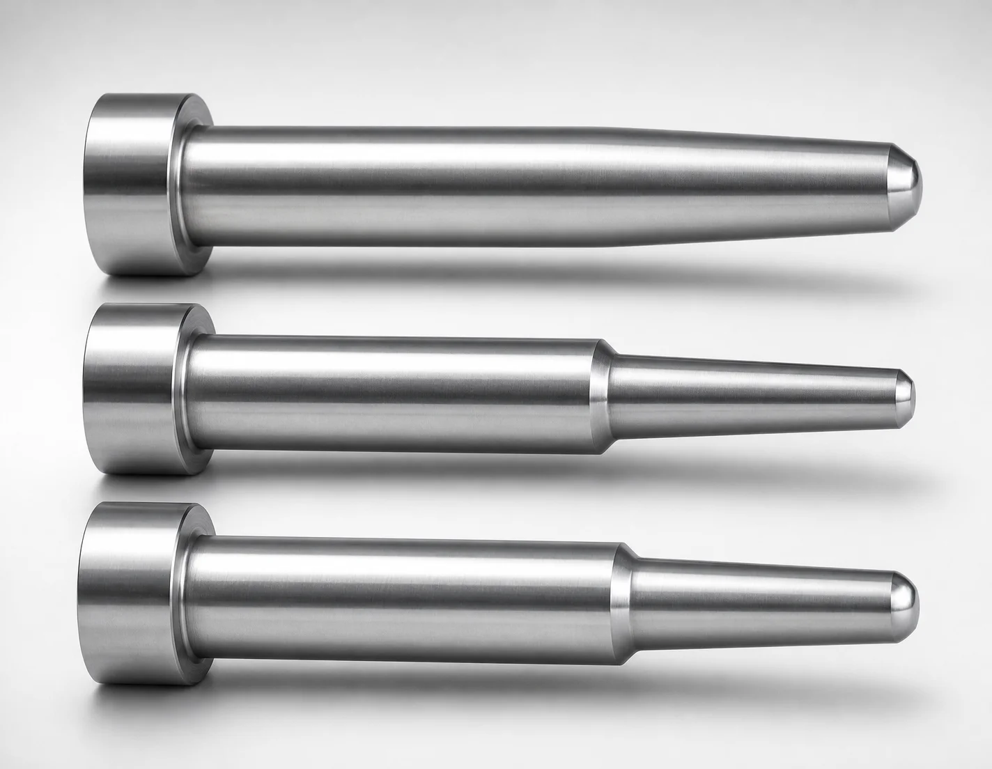
JIS Standard SKH51 Steel One-Step Core Pins - No Second Step
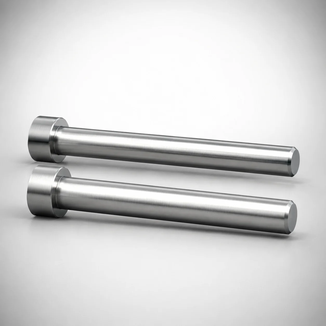
SKH51 Steel Precision Tip Short One-Step Core Pins
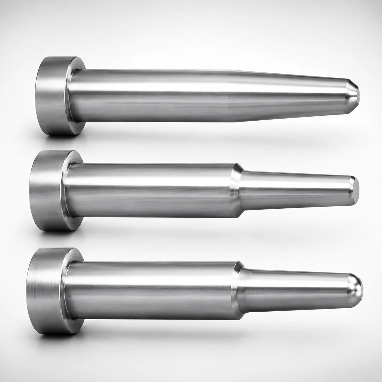
JIS Standard Precision One-Step Core Pins T4 Head
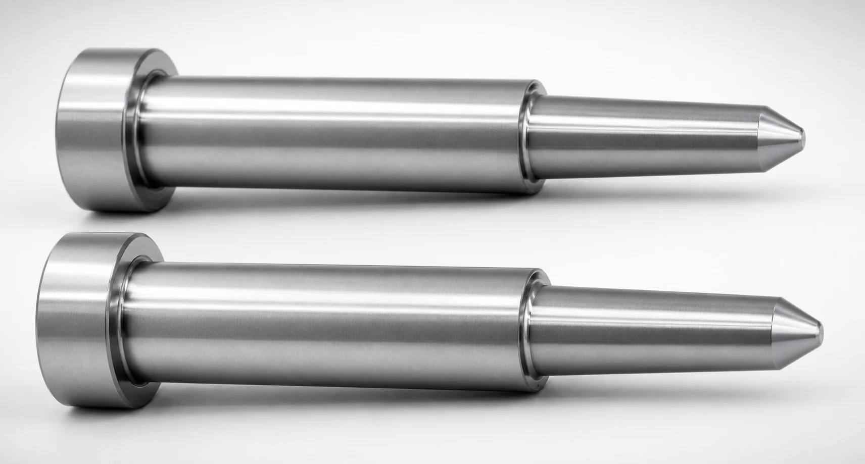
JIS Standard Precision One-Step Core Pins No Second Step
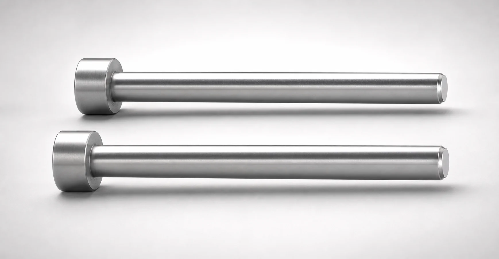
JIS Standard Precision Tip Short One-Step Core Pins
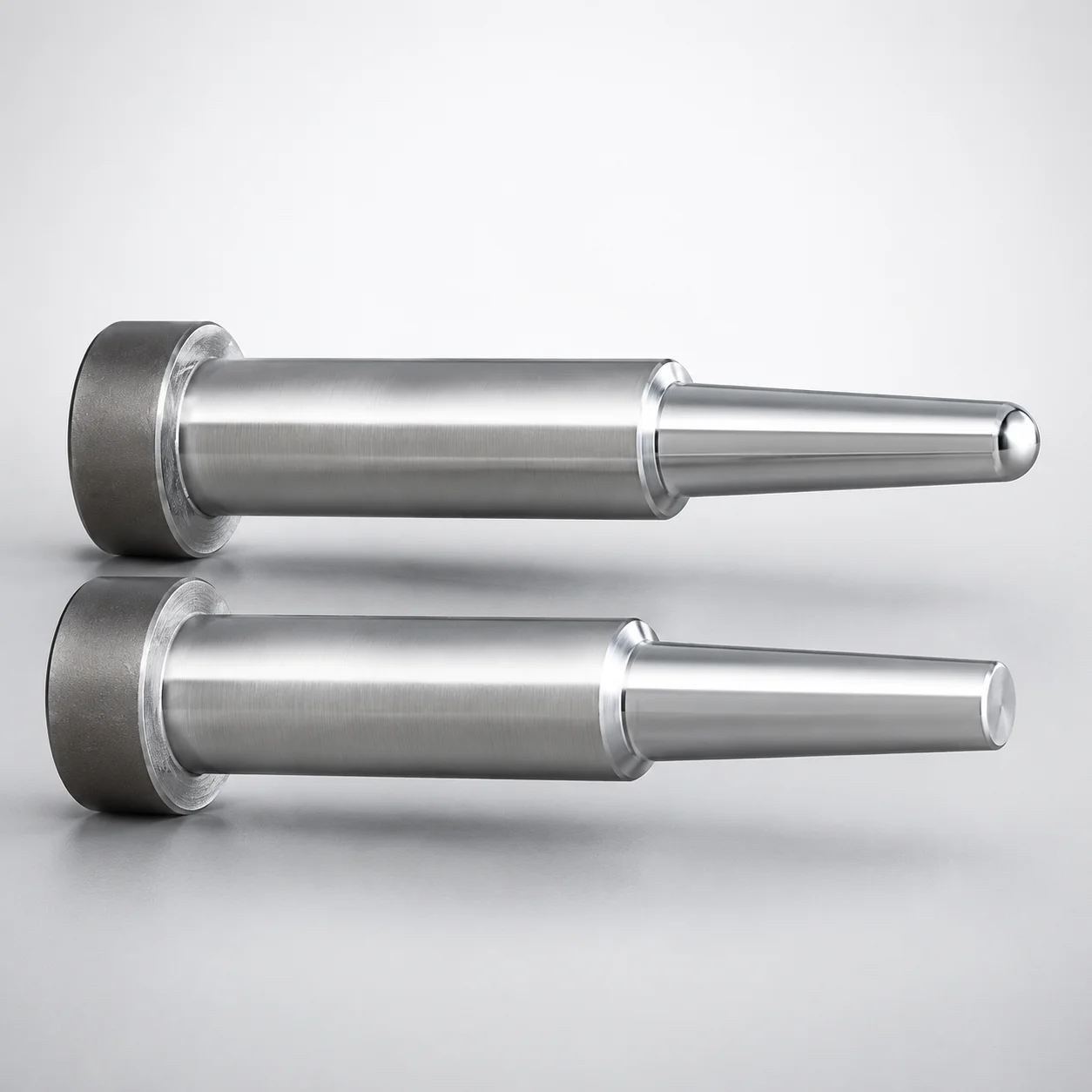
JIS Standard Steel One-Step Core Pins - Tip Lapped
Need Custom Specifications?
Our engineering team can help with custom configurations, material selection, and volume pricing.