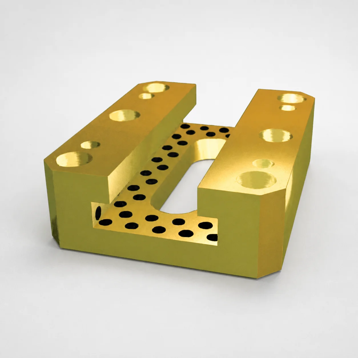
Inch Oil-Free Gib Assemblies With T-Slide Option
Inch oil-free gib assemblies with T-slide option (Lamina steel guide rails with copper alloy support) provide dependable linear guidance with smooth travel and stable alignment under load.
- Non-oil groove design with a no-groove heel and side groove geometry supports consistent positioning
- Copper alloy construction resists wear and helps maintain smooth motion in automated systems
- Optimized rail and heel interface geometry supports reliable operation across configured rail thickness and width options
- Built for inch equipment configurations, helping reduce misalignment risk and extend service life in demanding environments
Specifications
26 configurations available
| Rail thickness (in) | Rail width (in) | Rail length (in) | Heel height (in) | Heel width (in) | T-Slide |
|---|---|---|---|---|---|
| 1.12 | 2.62 | 2.00 | 0.312 | 1.5 | Without |
| 1.12 | 2.62 | 2.00 | 0.312 | 1.5 | With |
| 1.12 | 2.62 | 3.00 | 0.312 | 1.5 | Without |
| 1.12 | 2.62 | 3.00 | 0.312 | 1.5 | With |
| 1.12 | 2.62 | 4.00 | 0.312 | 1.5 | Without |
| 1.12 | 2.62 | 4.00 | 0.312 | 1.5 | With |
| 1.12 | 3.12 | 3.00 | 0.375 | 1.62 | Without |
| 1.12 | 3.12 | 3.00 | 0.375 | 1.62 | With |
| 1.12 | 3.12 | 4.00 | 0.375 | 1.62 | Without |
| 1.12 | 3.12 | 4.00 | 0.375 | 1.62 | With |
| 1.12 | 3.12 | 5.00 | 0.375 | 1.62 | Without |
| 1.12 | 3.12 | 5.00 | 0.375 | 1.62 | With |
| 1.25 | 4.12 | 3.00 | 0.5 | 2.37 | Without |
| 1.25 | 4.12 | 3.00 | 0.5 | 2.37 | With |
| 1.25 | 4.12 | 4.00 | 0.5 | 2.37 | Without |
| 1.25 | 4.12 | 4.00 | 0.5 | 2.37 | With |
| 1.25 | 4.12 | 5.00 | 0.5 | 2.37 | Without |
| 1.25 | 4.12 | 5.00 | 0.5 | 2.37 | With |
| 1.25 | 4.12 | 6.00 | 0.5 | 2.37 | Without |
| 1.25 | 4.12 | 6.00 | 0.5 | 2.37 | With |
| 1.62 | 4.62 | 4.00 | 0.75 | 2.62 | Without |
| 1.62 | 4.62 | 4.00 | 0.75 | 2.62 | With |
| 1.62 | 4.62 | 5.00 | 0.75 | 2.62 | Without |
| 1.62 | 4.62 | 5.00 | 0.75 | 2.62 | With |
| 1.62 | 4.62 | 6.00 | 0.75 | 2.62 | Without |
| 1.62 | 4.62 | 6.00 | 0.75 | 2.62 | With |
Product Guide
Application Scenarios+
These inch oil-free gib assemblies are used in injection mold tooling and automation where a slide or guide rail must hold alignment while moving under load. The T-slide option is especially helpful when engineers need to add mounting features for brackets, sensors, or auxiliary components on the moving platen or bolster.
- Automotive connector and insert molds: For linear guided movement of ejector-adjacent plates or small indexing slides, the copper alloy support area helps reduce wear at the rail/heel interface, supporting stable travel over production cycles.
- Packaging and material handling tooling: In systems with intermittent motion, the oil-free design (no oil groove approach) supports consistent positioning without relying on lubricant management during maintenance.
- Industrial machine subassemblies: Where inch-standard components are required, the configured rail thickness/width and heel height options help maintain proper fit to existing slide-plate geometry.
The variant’s copper alloy support and no-groove heel geometry make it well-suited for applications that prioritize smooth motion, reduced misalignment risk, and predictable long-term wear behavior.
Material & Process Details+
The assembly pairs Lamina steel guide rails with a copper alloy support heel. Copper alloys at the sliding interface are selected for their ability to resist wear and help maintain smooth motion by reducing abrasive transfer and fretting at the contact surfaces.
- Wear resistance vs. toughness trade-off: Copper-alloy supports generally favor low-friction, anti-wear behavior; the steel rail provides the structural stiffness needed to maintain alignment under load.
- Oil-free contact concept: The “oil-free” geometry is designed so the interface can operate without an oil-groove arrangement, shifting reliance to controlled mating surfaces and material compatibility.
- Heat treatment/manufacturing: The provided data specifies steel/copper alloy construction, but does not list a specific steel grade, hardness (HRC), or heat-treatment state (e.g., quenched & tempered, nitrided). Please request the material certificate if a target hardness or surface treatment is required for your mold standard.
When selecting alternatives, compare available rail steels and any surface treatments your maintenance and duty-cycle requirements demand.
Sizing & Selection Guide+
Select the gib assembly dimensions by matching the rail thickness and rail width to the slide-plate or guide-rail pocket geometry in your mold base or machine frame.
- Rail thickness (in): choose 1.12, 1.25, or 1.62 based on the rail stock thickness in the guided assembly.
- Rail width (in): select 2.62, 3.12, 4.12, or 4.62 to match the rail contact envelope and maintain full heel engagement.
- Rail length (in): pick 2.00, 3.00, 4.00, 5.00, or 6.00 to cover the intended travel and ensure stable guidance across the stroke.
- Heel height/width (in): match heel height 0.312, 0.375, 0.5, or 0.75 and heel width 1.5, 1.62, 2.37, or 2.62 to the receiving guide channel geometry for proper contact.
Use the T-Slide option (“Without” or “With”) to align mounting features with your design. If your mold requires a controlled fit (tight guidance, low rattle), verify clearances against your existing rail/plate tolerances; this product data lists dimensions but does not specify explicit tolerances, so confirm allowable play in your tolerance stack-up.
Frequently Asked Questions
How do I choose the correct rail thickness and heel height to prevent misalignment in inch slide assemblies?+
What rail width options are available, and how do they affect the contact envelope with the copper alloy support?+
When should I select the T-Slide option versus the without-T-Slide version?+
What rail length should I pick for a given stroke to ensure the heel remains engaged throughout travel?+
Does the provided data specify a steel grade, hardness (HRC), or heat treatment for performance verification?+
Related Products
Standard Type Mini Slide Core Units
Mini Slide Core Units Slim Type (3 mm Stroke) for Inlay Tapped MSCS-Type
Mini Slide Core Units Slim Slide Stroke 3 mm Retractor Mechanism
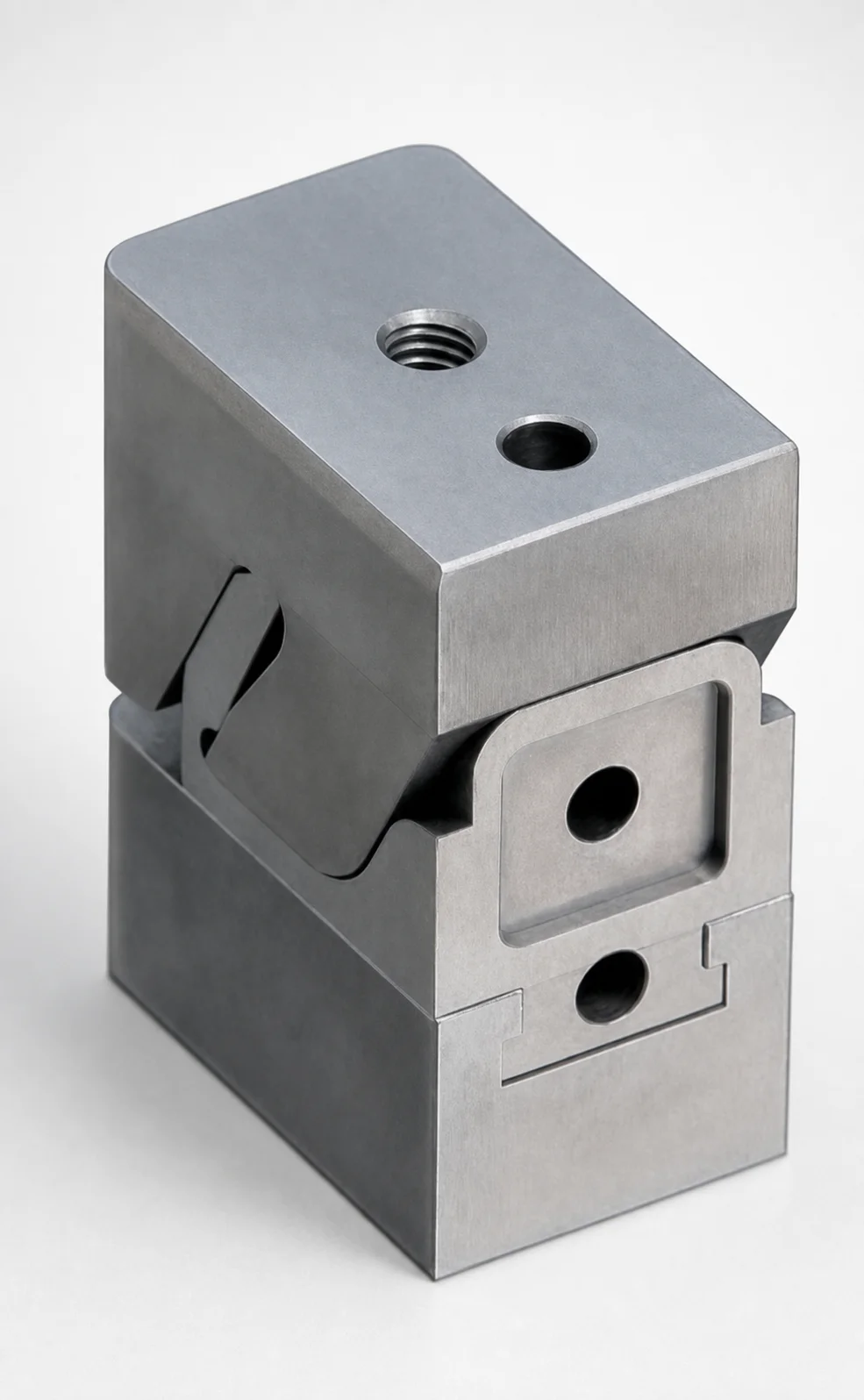
Mini Slide Core Units Slim Slide Stroke 10 mm Retracting Mechanism
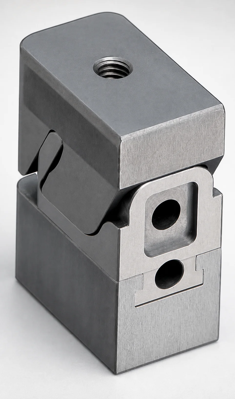
Mini Slide Core Units Slim Slide Core Retractor 6 mm Stroke
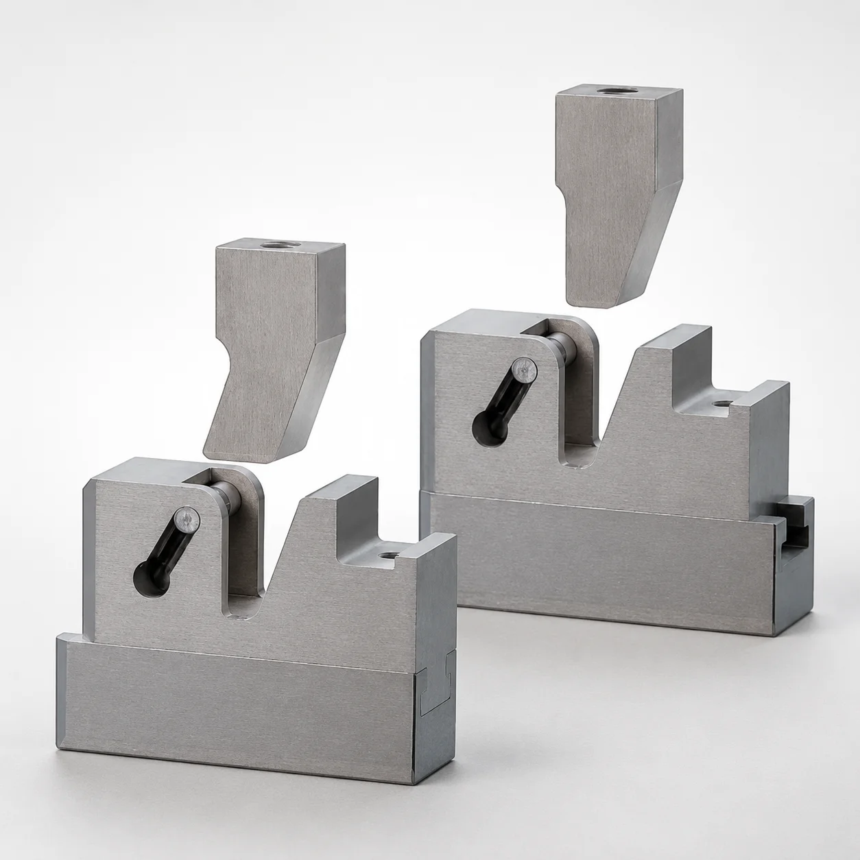
SCTM Two-Color Slide Core Units
Need Custom Specifications?
Our engineering team can help with custom configurations, material selection, and volume pricing.