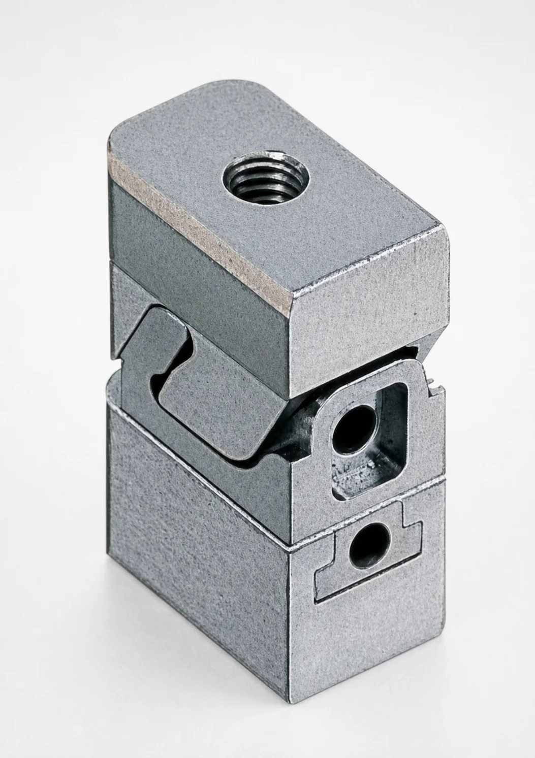
Mini Slide Core Units Slim Slide Stroke 3 mm Retractor Mechanism
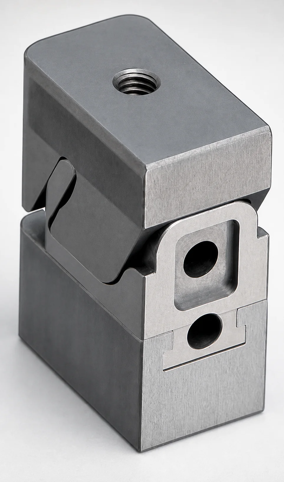
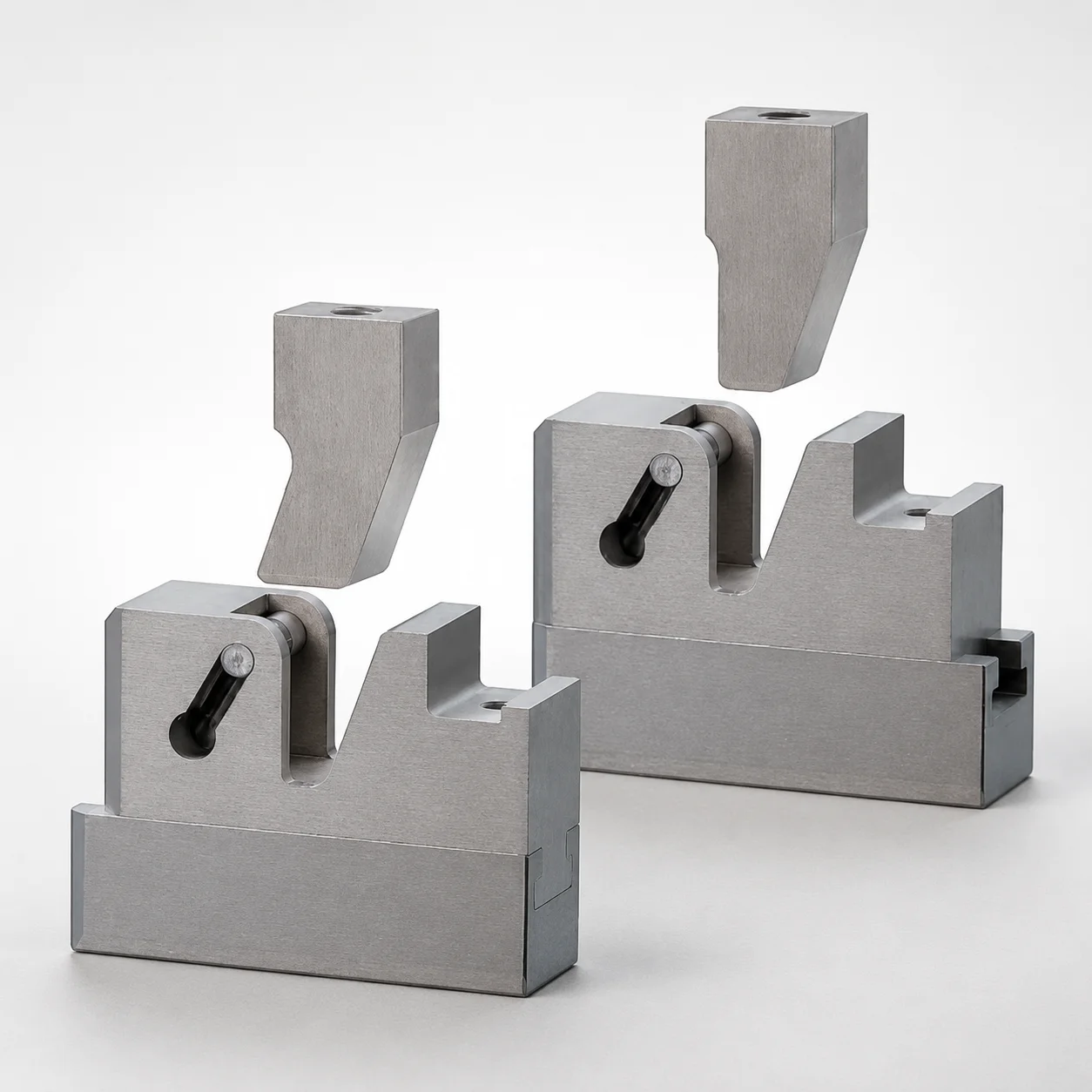
Mini Slide Core Units slim slide stroke 3 mm retractor mechanism are compact slide core assemblies designed to integrate a retracting function for reliable part release in space-limited molds.
- Slim type construction with 3 mm slide stroke supports precise mold cycling
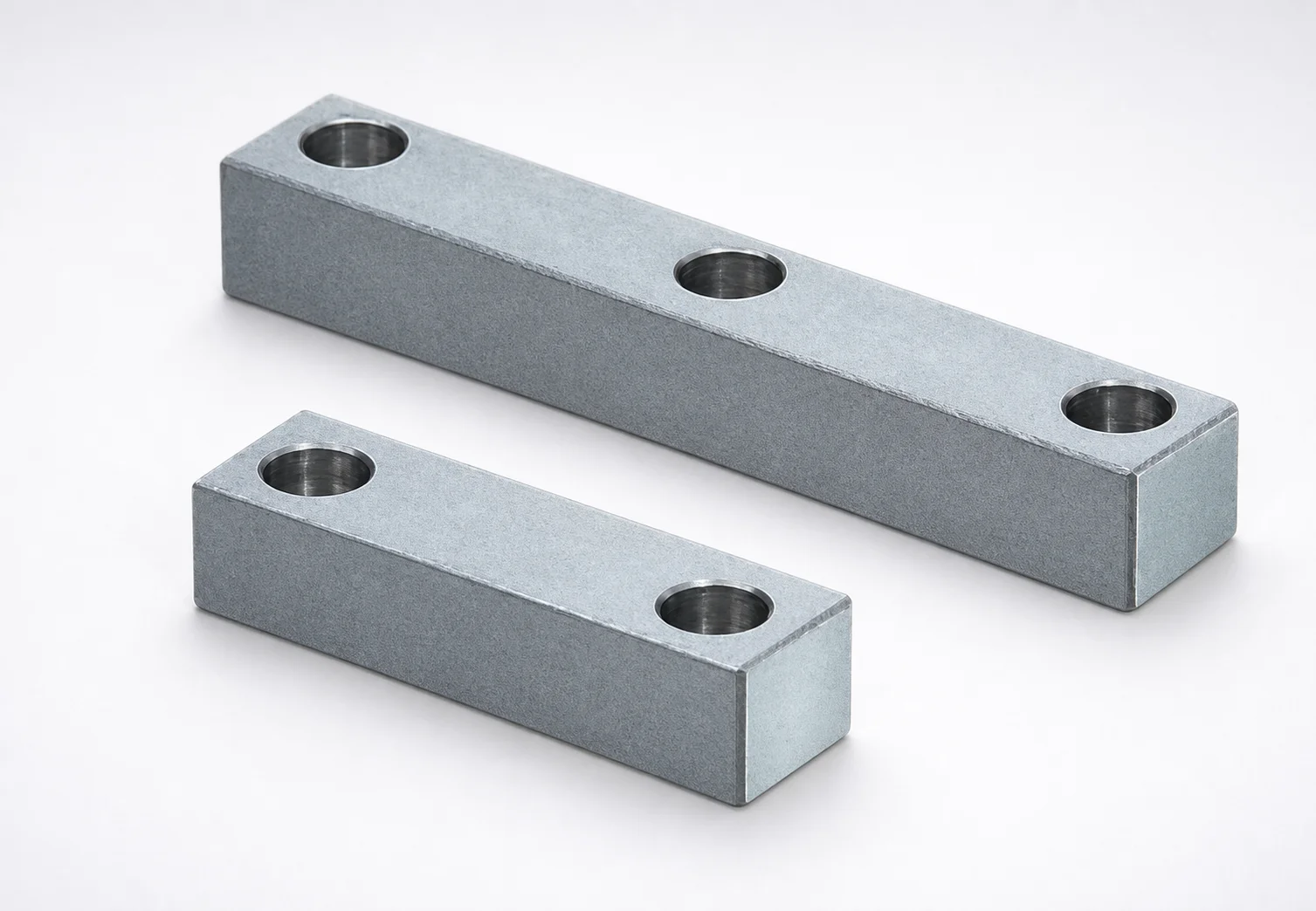
- Combined guide rail layout improves motion stability during core actuation
- Retracting mechanism helps return the slide core smoothly for repeatable operation
- Suitable for insert-style slide core use in precision plastic injection mold systems
Specifications
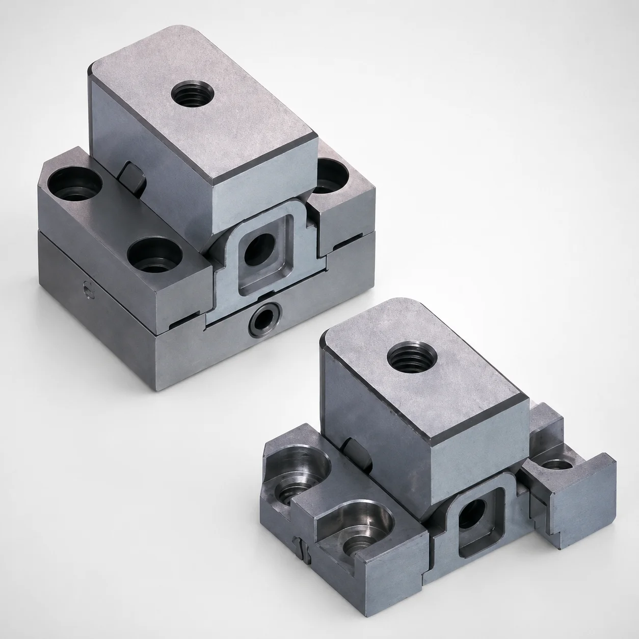
2 configurations available
| Slide Core | type |
|---|---|
| Inlay part processed | - |
| Tapped | - |
Product Guide
Application Scenarios+
This compact slide core unit is used in injection mold tooling where undercuts must be released through a controlled side motion, but the available die space is limited. The slim slide stroke designed for 3 mm actuation supports fast, repeatable core movement for precision cycling.
- Automotive interior/connector housings: Suitable for slide-core release of small undercuts around ribs or snap features while keeping overall mold thickness compact; the slim stroke helps match tight tolerance stack-ups.
- Electronics and appliance housings: Used to actuate inlay or insert processed features with improved motion stability, helping maintain alignment during core travel and return.
- Medical device housings (compact dies): The built-in retractor mechanism supports reliable return for consistent part release, which is valuable when dimensional control and surface quality are critical.
The combined guide rail layout and built-in retractor are well suited to prevent sticking and to return the core smoothly over repeated cycles.
Material & Process Details+
The provided specifications describe the slide core as an inlay part processed and tapped, but no explicit steel grade, hardness, or heat-treatment state is listed. Therefore, material selection should be verified against your project requirements (wear, corrosion resistance, and fatigue life) and the supplier’s material data for this specific unit.
- Heat treatment & hardness: Not specified in the given data; confirm whether the core is pre-hardened or quenched & tempered prior to machining and assembly.
- Wear vs. toughness trade-off: Slide cores typically require balanced wear resistance and adequate toughness to resist cyclic loading; the best grade depends on cavity surface finish, tonnage, and expected cycle count.
- Compatibility: Since the inlay is processed and tapped, confirm thread form and fit after any heat treatment/finishing step.
If multiple material options exist, select based on the mold’s abrasion level and whether corrosion inhibitors or cleaning agents are used.
Sizing & Selection Guide+
Selection is primarily driven by the 3 mm slim slide stroke, which determines the required core travel to clear undercut features without overtravel. Match the stroke to the depth and geometry of the undercut region in the cavity/core layout, allowing margin for part deformation and ejector resistance.
- Stroke requirement: Ensure the mechanism’s 3 mm travel covers the full clearance needed for the inlay/insert feature release.
- Mounting/processing condition: The slide core is described as an inlay part processed, tapped. Verify that your backing plate/core block has the corresponding tapped locations and that the inlay dimensions and thread specification align with your design.
- Tolerance & fit: For smooth actuation, maintain consistent clearances around guide paths and ensure the tapped mounting interfaces provide sufficient thread engagement without bottoming.
Where the unit dimensions are configurable (e.g., mounting interface via tapping), lock the core cavity/core drawing to the unit’s interface drawing before final machining.
Frequently Asked Questions
How do I size the slide core travel for an undercut when using a 3 mm slim slide stroke unit?+
What mounting interface should I design for, given that the slide core is an inlay part processed and tapped?+
What guide or stability considerations apply when integrating this compact retractor slide core into a space-limited die?+
Is this unit suitable for insert-style slide core applications in precision injection molding?+
Do I need to confirm the steel grade and hardness for wear and fatigue life?+
Related Products
Need Custom Specifications?
Our engineering team can help with custom configurations, material selection, and volume pricing.