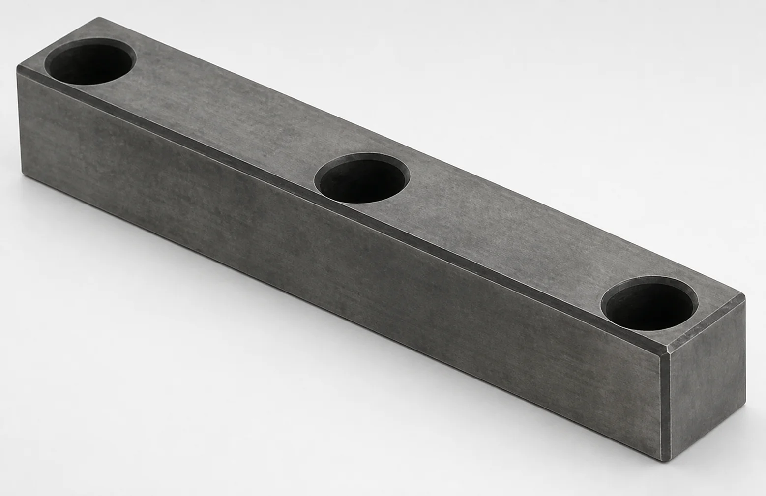
Plain Guide Rails (HPM2T Steel) Nitriding Treatment
Plain guide rails (HPM2T steel) with nitriding treatment provide stable, low-wear linear guidance for industrial slides and machine tool assemblies. The no-groove heel design supports clean lubrication strategies while maintaining consistent rail contact.
- Precise guide rail form for straight, repeatable motion in slide mechanisms
- Nitriding treatment enhances surface hardness for improved wear resistance
- Configurable lubrication build via oil groove or non-oil groove options
- Typical use with gibs and guide systems requiring reliable positioning
Specifications
102 configurations available
| Oil Groove | Rail Thickness T (mm) | Rail Width W (mm) | Rail Length L (mm) | type |
|---|---|---|---|---|
| Oil groove | 15 | 20 | 80 | - |
| Oil groove | 15 | 20 | 90 | - |
| Oil groove | 15 | 20 | 100 | - |
| Oil groove | 15 | 20 | 110 | - |
| Oil groove | 15 | 20 | 120 | - |
| Oil groove | 15 | 20 | 130 | - |
| Oil groove | 15 | 20 | 140 | - |
| Oil groove | 15 | 20 | 150 | - |
| Oil groove | 20 | 20 | 80 | - |
| Oil groove | 20 | 20 | 90 | - |
| Oil groove | 20 | 20 | 100 | - |
| Oil groove | 20 | 20 | 110 | - |
| Oil groove | 20 | 20 | 120 | - |
| Oil groove | 20 | 20 | 130 | - |
| Oil groove | 20 | 20 | 140 | - |
| Oil groove | 20 | 20 | 150 | - |
| Oil groove | 25 | 20 | 80 | - |
| Oil groove | 25 | 20 | 90 | - |
| Oil groove | 25 | 20 | 100 | - |
| Oil groove | 25 | 20 | 110 | - |
| Oil groove | 25 | 20 | 120 | - |
| Oil groove | 25 | 20 | 130 | - |
| Oil groove | 25 | 20 | 140 | - |
| Oil groove | 25 | 20 | 150 | - |
| Oil groove | 30 | 20 | 80 | - |
| Oil groove | 30 | 20 | 90 | - |
| Oil groove | 30 | 20 | 100 | - |
| Oil groove | 30 | 20 | 110 | - |
| Oil groove | 30 | 20 | 120 | - |
| Oil groove | 30 | 20 | 130 | - |
| Oil groove | 30 | 20 | 140 | - |
| Oil groove | 30 | 20 | 150 | - |
| Oil groove | 20 | 25 | 80 | - |
| Oil groove | 20 | 25 | 90 | - |
| Oil groove | 20 | 25 | 100 | - |
| Oil groove | 20 | 25 | 110 | - |
| Oil groove | 20 | 25 | 120 | - |
| Oil groove | 20 | 25 | 130 | - |
| Oil groove | 20 | 25 | 140 | - |
| Oil groove | 20 | 25 | 150 | - |
| Oil groove | 25 | 25 | 80 | - |
| Oil groove | 25 | 25 | 90 | - |
| Oil groove | 25 | 25 | 100 | - |
| Oil groove | 25 | 25 | 110 | - |
| Oil groove | 25 | 25 | 120 | - |
| Oil groove | 25 | 25 | 130 | - |
| Oil groove | 25 | 25 | 140 | - |
| Oil groove | 25 | 25 | 150 | - |
| Oil groove | 30 | 25 | 80 | - |
| Oil groove | 30 | 25 | 90 | - |
Product Guide
Application Scenarios+
These plain guide rails are used in injection molding auxiliary mechanisms and other high-cycle machine slide assemblies where smooth linear motion and consistent positioning matter. The nitrided surface is designed to resist abrasive wear and help maintain rail-to-gib contact over long service intervals.
- Automated mold handling and lifter slides: Select rails in the 15–30 mm thickness range and 80–150 mm lengths to match compact slide frames, using the oil groove or non-oil groove option to fit your lubrication strategy.
- Machine tool or servo-driven guide systems: The hardened, nitriding-treated contact area supports stable motion with low scuffing during repeated start/stop cycles.
- Undercut-plate slide mechanisms with gibs: Their straight, repeatable guide form works well with gib-based guidance where tight alignment between adjacent plates is critical.
Choose the variant based on how you deliver lubrication (oil groove vs non-oil groove) while keeping the specified T, W, and L aligned to your core/plate geometry.
Material & Process Details+
This guide rail is made from HPM2T steel and is supplied with a nitriding treatment. Nitriding increases surface hardness and improves wear resistance without significantly reducing the toughness of the steel core—an important balance for slide guidance where both abrasion and impact micro-loading can occur.
- Hardness & wear: The nitrided layer is intended to provide a hard, wear-resistant surface for stable rail-to-gib sliding and reduced scoring.
- Toughness trade-off: Nitriding hardens mainly the surface, helping maintain a tougher core compared with through-hardened steels.
- Manufacturing process: Typically involves machining the rail to size, followed by nitriding (and any required finishing) to achieve the final surface characteristics.
Material alternatives are not provided in the input data; when comparing options, select based on whether your application prioritizes surface wear resistance (nitriding) versus through-hardness for deeper wear penetration.
Sizing & Selection Guide+
Select rail dimensions to match the guided interface geometry of your slide mechanism (guide rail, gib, and mounting surface). Use the provided parameter ranges to ensure the rail occupies the correct space and supports the intended contact width.
- Thickness (T): Choose T = 15, 20, 25, or 30 mm to match the guide seat and support stiffness in your moving assembly.
- Width (W): Choose W = 20 or 25 mm to set the effective bearing area between the rail and gib.
- Length (L): Choose L = 80 to 150 mm to cover the required travel/contact zone.
After dimension selection, confirm fit and alignment with your guide plate layout: ensure the rail length aligns with the mounting datum so the gib load is distributed along the rail. The input data lists configurable lubrication features (oil groove vs non-oil groove); all T/W/L dimensions are fixed options within the stated ranges.
Frequently Asked Questions
Which lubrication build should I select: oil groove or non-oil groove, for stable slide guidance?+
How do I choose rail thickness T (15/20/25/30 mm) to prevent uneven gib contact?+
What rail width W (20 vs 25 mm) is appropriate for bearing area and wear control?+
How should I set rail length L (80–150 mm) relative to travel and mounting datums?+
What benefit does nitriding treatment provide for guide rails in sliding mechanisms?+
Related Products
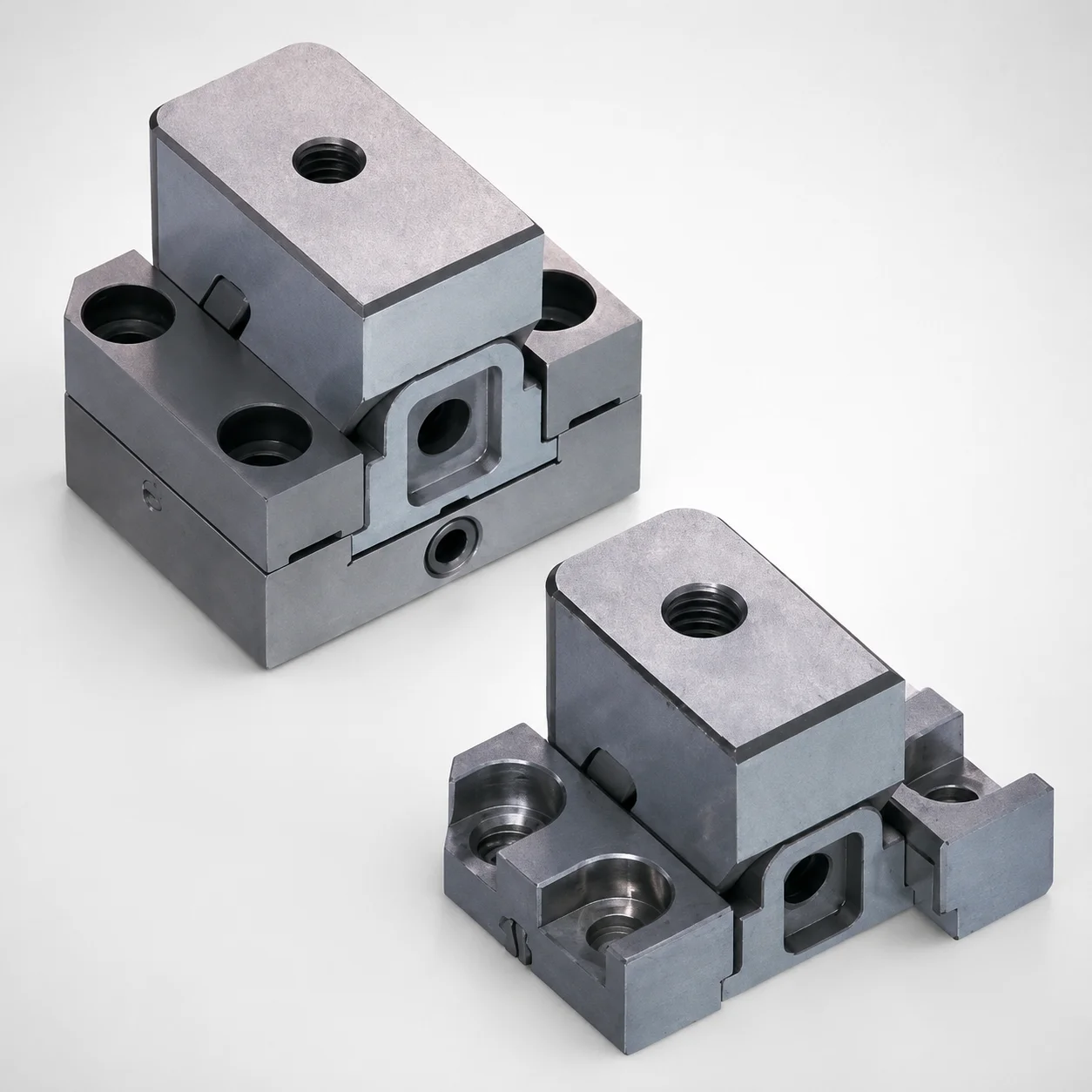
Standard Type Mini Slide Core Units
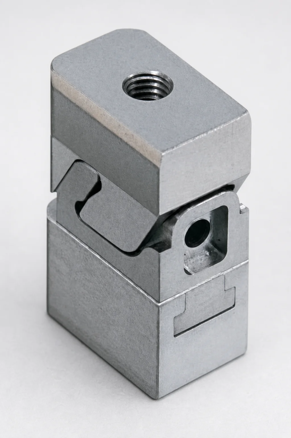
Mini Slide Core Units Slim Type (3 mm Stroke) for Inlay Tapped MSCS-Type
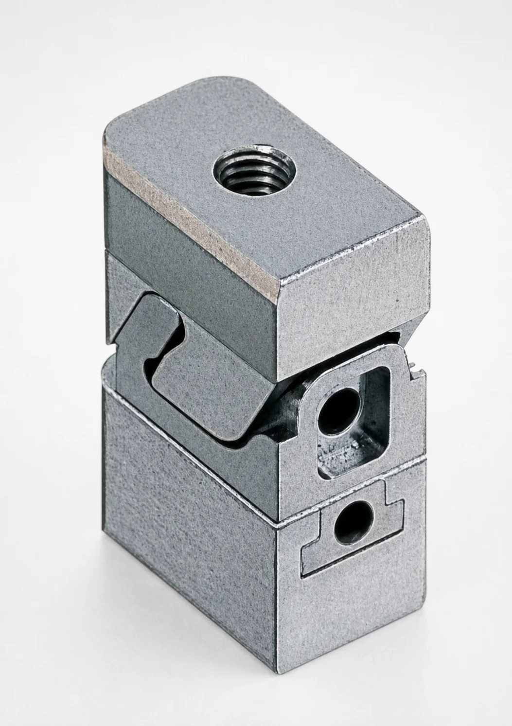
Mini Slide Core Units Slim Slide Stroke 3 mm Retractor Mechanism
Mini Slide Core Units Slim Slide Stroke 10 mm Retracting Mechanism
Mini Slide Core Units Slim Slide Core Retractor 6 mm Stroke
SCTM Two-Color Slide Core Units
Need Custom Specifications?
Our engineering team can help with custom configurations, material selection, and volume pricing.