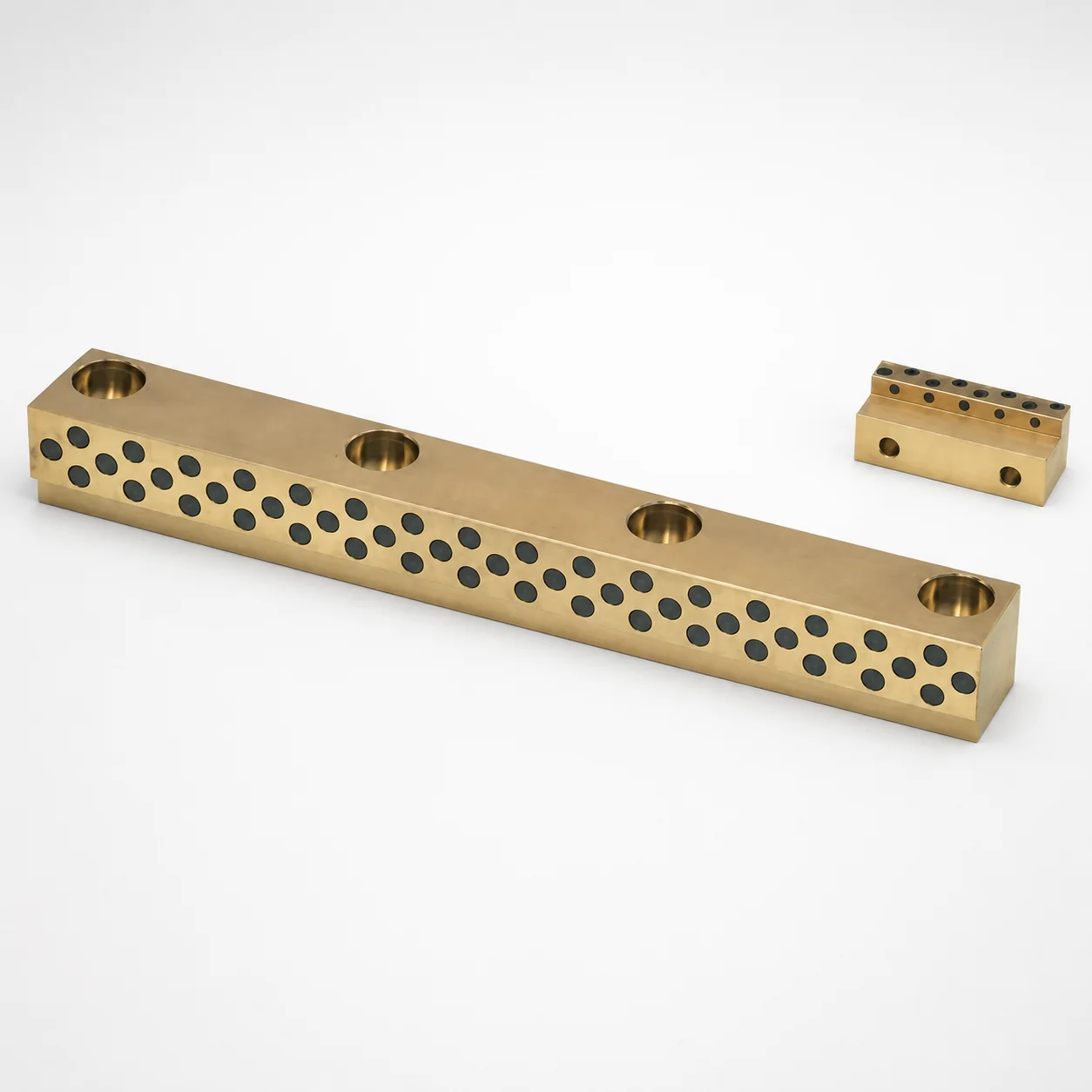
Copper Alloy Oil-Free Heel Guide Rails (No Groove, Heel Height 5 mm)
Oil-free heel guide rails (copper alloy) with no groove and 5 mm heel height are designed for clean, maintenance-friendly guidance in sliding assemblies. They support stable rail seating and smooth motion while avoiding oil groove contamination risks.
- No groove heel maintains a clean contact area for reliable, oil-free guidance
- Copper alloy construction offers good wear resistance for repeated sliding cycles
- Designed for configurable bolt hole pitch to match different mounting layouts
- Commonly used in machine tool gib systems and linear guide assemblies
Specifications
14 configurations available
| Rail Thickness T (mm) | Rail Width W (mm) | Rail Length L (mm) | No. of mounting holes (pieces) | A (Bolt hole pitch) (mm) | B (Bolt hole pitch) (mm) | type |
|---|---|---|---|---|---|---|
| 15 ~ 20 | 12.5 | 40 ~ 70 | 2 | 6 ~ 54 | 16 ~ 64 | - |
| 15 ~ 25 | 15 | 40 ~ 70 | 2 | 7 ~ 51.5 | 18.5 ~ 63 | - |
| 15 ~ 30 | 20 | 40 ~ 150 | 2 | 7.5 ~ 129.5 | 20.5 ~ 142.5 | - |
| 20 ~ 30 | 25 | 40 ~ 150 | 2 | 9 ~ 125 | 25 ~ 141 | - |
| 15 ~ 20 | 12.5 | 60 ~ 100 | 3 | 6 ~ 44 | 16 ~ 84 | - |
| 15 ~ 25 | 15 | 60 ~ 150 | 3 | 7 ~ 120 | 18.5 ~ 131.5 | - |
| 15 ~ 30 | 20 | 100 ~ 150 | 3 | 7.5 ~ 166.5 | 20.5 ~ 179.5 | - |
| 15 ~ 30 | 20 | 160 ~ 200 | 3 | 7.5 ~ 166.5 | 20.5 ~ 179.5 | - |
| 20 ~ 30 | 25 | 100 ~ 150 | 3 | 9 ~ 159 | 25 ~ 175 | - |
| 20 ~ 30 | 25 | 160 ~ 200 | 3 | 9 ~ 159 | 25 ~ 175 | - |
| 15 ~ 20 | 12.5 | - | 4 | 6 ~ 64 | 16 ~ 74 | - |
| 15 ~ 25 | 15 | 100 ~ 150 | 4 | 7 ~ 108.5 | 18.5 ~ 120 | - |
| 15 ~ 30 | 20 | 160 ~ 200 | 4 | 7.5 ~ 153.5 | 20.5 ~ 166.5 | - |
| 20 ~ 30 | 25 | 160 ~ 200 | 4 | 9 ~ 143 | 25 ~ 159 | - |
Product Guide
Application Scenarios+
These copper alloy, oil-free heel guide rails are used in injection mold tooling wherever a stable sliding interface is needed but contamination from lubricant reservoirs is undesirable. The no-groove heel design helps maintain a clean contact zone, supporting consistent seating and smooth relative motion under repeated opening and closing cycles.
- Machine tool gib systems / slide mechanisms: The rail heel height of 5 mm provides predictable geometry for locating the mating surfaces, improving guidance stability and reducing the risk of oil groove carryover.
- Linear guide and slide plate assemblies: Available rail widths (W = 12.5–25 mm) and lengths (L = 40–200 mm) allow matching to core/cavity support layouts that require rigid, low-maintenance motion control.
- Maintenance-friendly mold upgrades: The configurable mounting holes (2–4 holes, with pitch A = 6–9 mm and B = 16–25 mm) enable retrofit onto different base plates without redesigning the entire slide base.
Material & Process Details+
The product uses a copper alloy selected for sliding service where oil-free operation and wear resistance are priorities. In heel-guide applications, copper alloys can provide stable friction and good durability under repeated relative motion, supporting long maintenance intervals.
- Wear resistance vs. toughness: Copper alloys are generally chosen for smooth sliding performance and resistance to surface wear; however, the material may trade off impact toughness compared with higher-hardness steel guide components.
- Heat treatment: No specific grade, hardness (HRC), or heat-treatment state is provided in the supplied data, so no HRC or quench/temper/nitriding claims are made here.
- Manufacturing process: The rails are produced to tight dimensional control for mounting-hole geometry and heel height (5 mm), supporting reliable rail seating in slide systems.
If your mold design requires comparative performance versus steel guide rails, specify the target load, cycle count, and allowable wear rate so material selection can be validated.
Sizing & Selection Guide+
Correct selection is driven by matching the rail’s heel geometry and the mating plate’s mounting layout. This series provides a fixed heel height of 5 mm, so you primarily choose T (rail thickness), W (rail width), L (rail length), and the mounting-hole pattern.
- Thickness (T): Choose from 15–20, 15–25, 15–30, or 20–30 mm to match the base or slide plate step and ensure proper load transfer.
- Width (W): Select 12.5, 15, 20, or 25 mm based on available bearing area and contact width constraints.
- Length (L): Match the available travel/gib span using ranges such as 40–70, 40–150, 60–100, 60–150, 100–150, or 160–200 mm.
- Mounting holes: Confirm the required number of holes (2–4) and pitch: A = 6–9 mm and B = 16–25 mm. Use these pitches to align with the mating plate’s threaded holes for proper rail seating.
Where the mating plate layout varies, the configurable hole pitch and hole count help avoid custom plate rework.
Frequently Asked Questions
How do I choose rail length (L) for a heel-guide in an injection mold slide assembly?+
What do the mounting-hole pitch ranges (A and B) mean for plate compatibility?+
Why is the “no groove” heel height of 5 mm beneficial compared with grooved heel guides?+
How should I select rail thickness (T) and width (W) to prevent misalignment in sliding motion?+
Is there a specified hardness (HRC) or heat treatment state for this copper alloy rail?+
Related Products
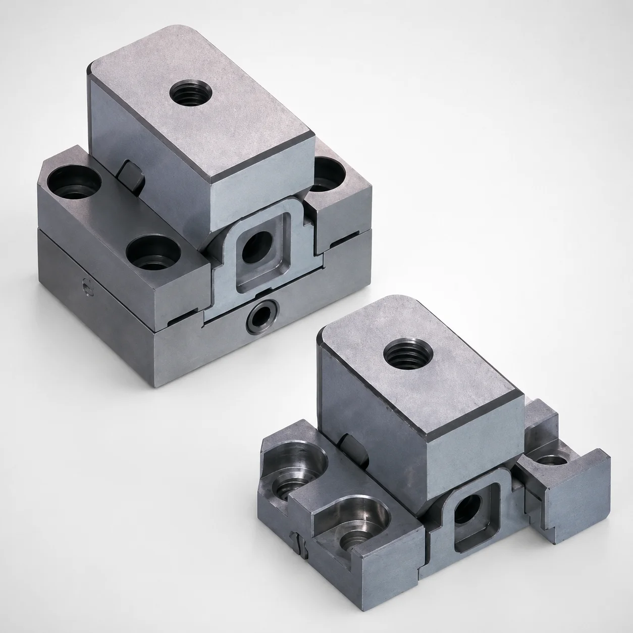
Standard Type Mini Slide Core Units
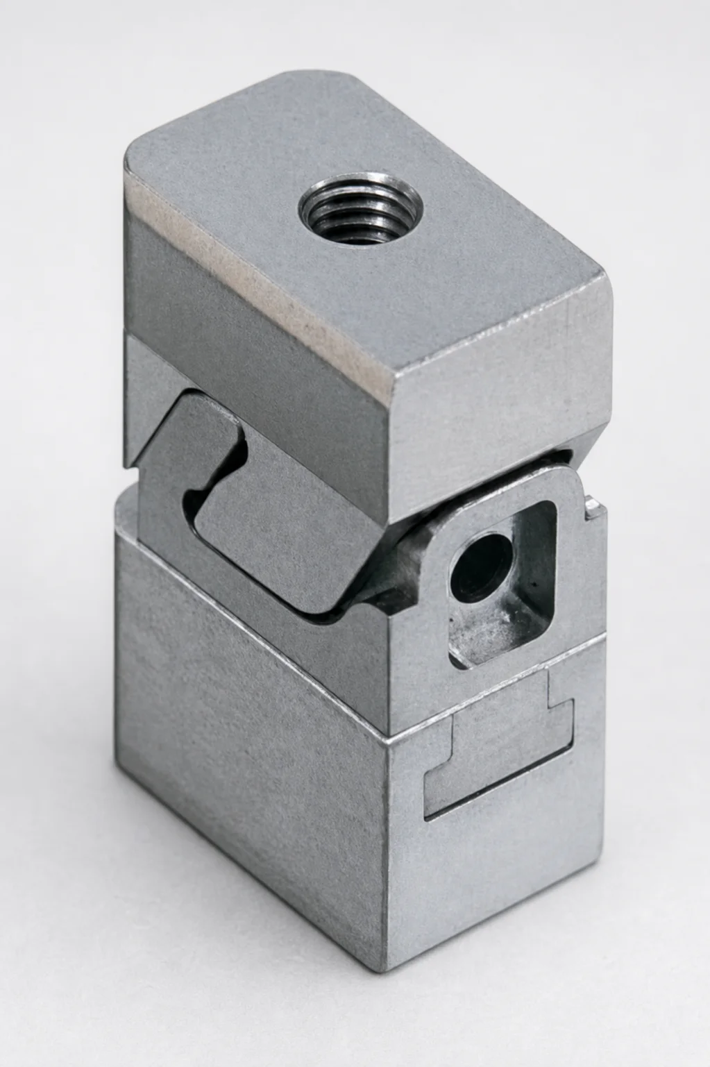
Mini Slide Core Units Slim Type (3 mm Stroke) for Inlay Tapped MSCS-Type
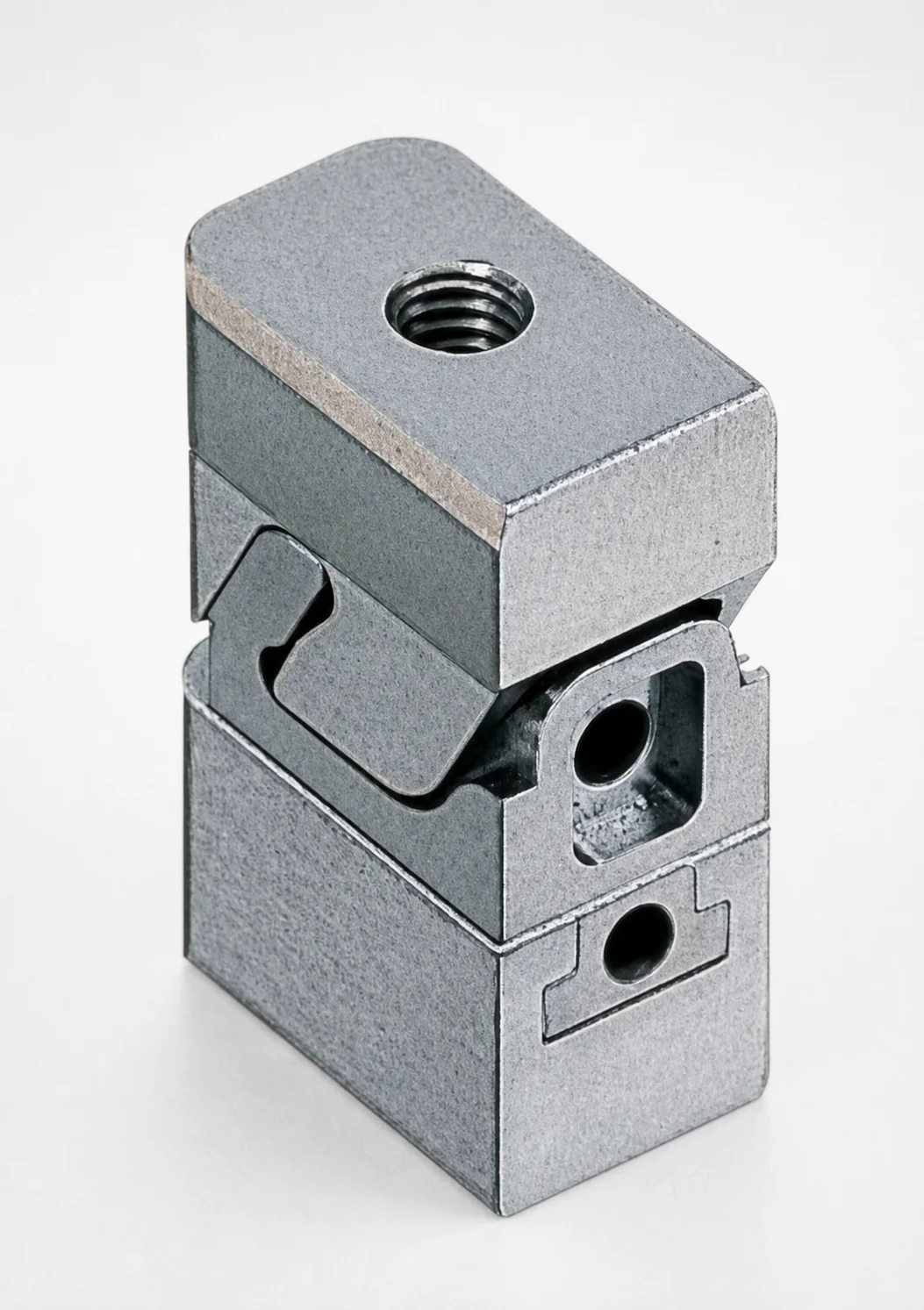
Mini Slide Core Units Slim Slide Stroke 3 mm Retractor Mechanism
Mini Slide Core Units Slim Slide Stroke 10 mm Retracting Mechanism
Mini Slide Core Units Slim Slide Core Retractor 6 mm Stroke
SCTM Two-Color Slide Core Units
Need Custom Specifications?
Our engineering team can help with custom configurations, material selection, and volume pricing.