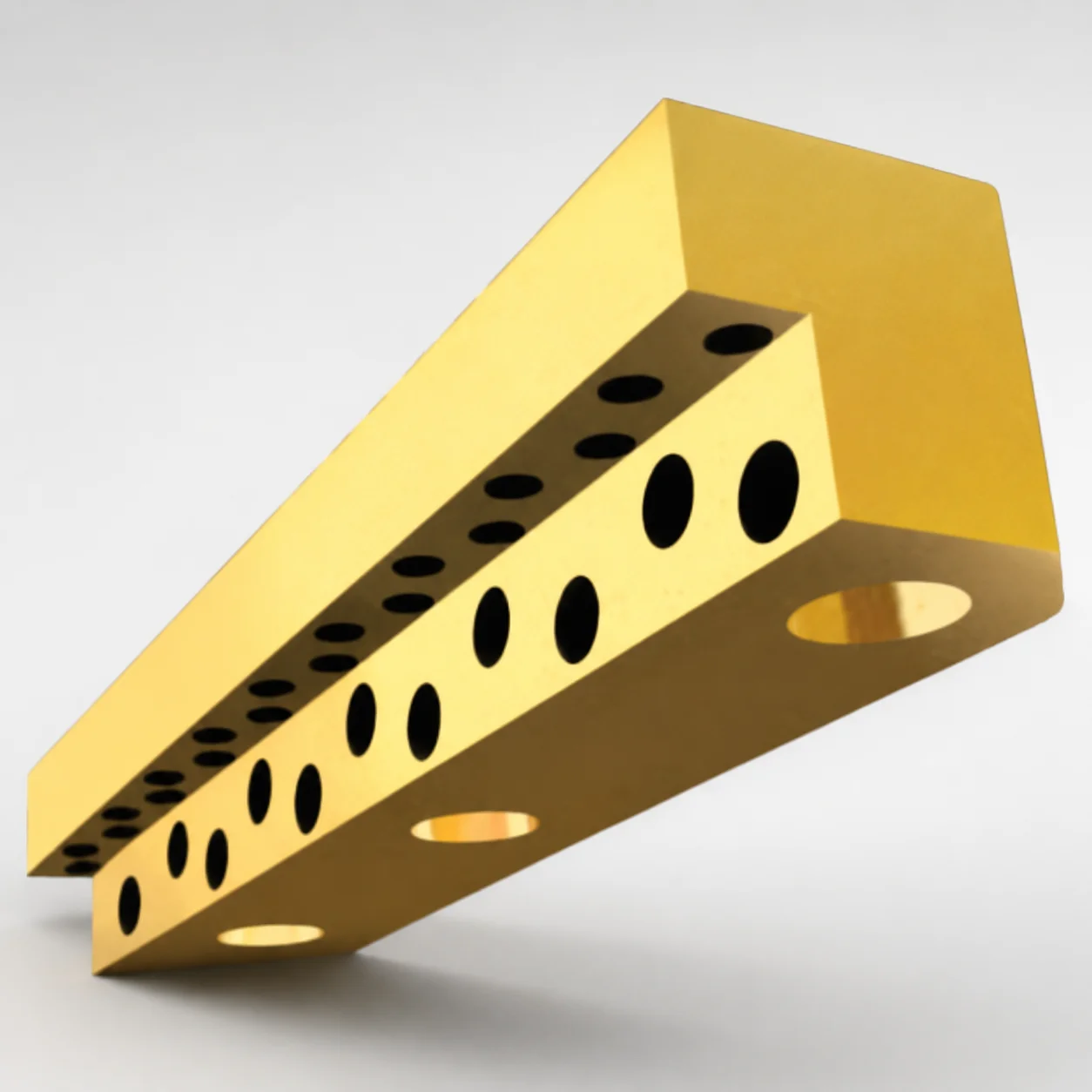
Inch L-Gibs for Gib Assemblies Non-Oil Groove
Inch L-Gibs for Gib Assemblies (non-oil groove) (Lamina) are designed to stabilize gib motion while maintaining clean, oil-free sliding performance. These guide rails support alignment in industrial machinery and help reduce wear during repeated travel.
- Non-oil groove design supports clean sliding motion and reliable alignment
- Copper alloy construction balances wear resistance for continuous operation
- Heel geometry and rail form factor support consistent guidance under load
- Compatible with inch gib assemblies for machine slide and positioning systems
Specifications
13 configurations available
| Rail thickness (in) | Rail width (in) | Rail length (in) | Heel height (in) | Heel width (in) | Mounting hole qty. | Mounting Hole Size |
|---|---|---|---|---|---|---|
| 0.75 | 0.75 | 2.00 | 0.312 | 0.188 | 2 | 1/4" |
| 0.75 | 0.75 | 3.00 | 0.312 | 0.188 | 2 | 1/4" |
| 0.75 | 0.75 | 4.00 | 0.312 | 0.188 | 3 | 1/4" |
| 0.75 | 1 | 3.00 | 0.375 | 0.25 | 2 | 5/16" |
| 0.75 | 1 | 4.00 | 0.375 | 0.25 | 3 | 5/16" |
| 0.75 | 1 | 5.00 | 0.375 | 0.25 | 3 | 5/16" |
| 0.88 | 1.25 | 3.00 | 0.5 | 0.375 | 2 | 5/16" |
| 0.88 | 1.25 | 4.00 | 0.5 | 0.375 | 3 | 5/16" |
| 0.88 | 1.25 | 5.00 | 0.5 | 0.375 | 3 | 5/16" |
| 0.88 | 1.25 | 6.00 | 0.5 | 0.375 | 4 | 5/16" |
| 1.25 | 1.5 | 4.00 | 0.75 | 0.5 | 3 | 5/16" |
| 1.25 | 1.5 | 5.00 | 0.75 | 0.5 | 3 | 5/16" |
| 1.25 | 1.5 | 6.00 | 0.75 | 0.5 | 4 | 5/16" |
Product Guide
Application Scenarios+
This non-oil groove L-gib style guide rail is used in injection mold tooling wherever linear slide alignment must stay consistent without relying on oil delivery to the contact surfaces. In mold base slide systems—such as shut-off or moving mold shoe assemblies—the rail’s clean, oil-free motion supports repeatable positioning and reduces contamination risk in precision cavities.
It is also suitable for precision lifter and undercut actuation mechanisms where debris control and stable guidance under intermittent loads are critical. The oil-free groove concept helps maintain sliding performance over repeated cycles, which is valuable when mold area cleanliness is tightly controlled.
- Used with inch gib assemblies for machine slide and positioning systems to maintain stable alignment.
- Copper alloy construction supports wear resistance in continuous operation.
- Heel geometry supports consistent guidance under load, helping reduce stick-slip during travel.
Material & Process Details+
The rail is described as a copper alloy construction. Copper alloys are commonly selected for guide components because they provide good wear resistance and stable sliding behavior against mating gib surfaces during repeated travel.
While this product page does not provide a specific copper alloy designation, hardness and heat-treatment state are not explicitly stated in the supplied data. Therefore, exact values such as HRC and whether the parts are quenched & tempered, nitrided, or otherwise heat treated cannot be confirmed from the provided specifications.
- Wear vs. toughness: copper alloys typically emphasize galling resistance and smooth sliding, trading off the very high hardness seen in fully hardened tool steels.
- Manufacturing process: dimensional control for heel/rail geometry is critical for consistent gib guidance; final fit relies on the specified rail thickness/width/length and mounting hole parameters.
Sizing & Selection Guide+
To select the correct L-gib components for a gib assembly, match the rail’s thickness, width, and length to the mating guide channels and the required travel length. The available rail thickness is 0.75, 0.88, or 1.25 in, and the rail width options are 0.75, 1, 1.25, or 1.5 in.
Choose the rail length based on the effective guidance span: available lengths are 2.00, 3.00, 4.00, 5.00, or 6.00 in. Heel geometry should be selected to fit the gib assembly interface: heel height options are 0.312, 0.375, 0.5, or 0.75 in; heel width options are 0.188, 0.25, 0.375, or 0.5 in.
- Confirm mounting compatibility using hole count (2, 3, or 4) and hole size (1/4 in or 5/16 in).
- If you’re designing a new tool, allow for normal assembly clearance in the slide to prevent binding; the correct fit depends on your gib assembly clearances and mating surfaces.
Frequently Asked Questions
Which rail thickness and width combinations are available for Lamina inch L-gibs with a non-oil groove?+
Rail thickness is offered at 0.75, 0.88, and 1.25 in. Rail width options are 0.75, 1, 1.25, and 1.5 in. Select the combination that matches your gib assembly channel dimensions and load-bearing alignment requirements.
How do I choose the right rail length for the guidance span in an inch gib assembly?+
The available rail lengths are 2.00, 3.00, 4.00, 5.00, and 6.00 in. Use the guidance span required for stable travel in your mold slide or positioning system, then verify the heel height/width options still provide full interface support.
What heel dimensions should I verify to ensure proper interface fit with the gib assembly?+
Heel height options are 0.312, 0.375, 0.5, and 0.75 in, and heel width options are 0.188, 0.25, 0.375, and 0.5 in. Confirm these match the gib assembly’s mating geometry so the rail supports consistent guidance under load.
Are mounting hole size and quantity specified—what do I need to match on the tool base?+
Mounting hole quantity is available as 2, 3, or 4. Mounting hole size options are 1/4 in and 5/16 in. Ensure your mold base or slide plate is designed with compatible hole positions and diameters for correct installation.
What does “non-oil groove” mean for wear and contamination control in mold slide applications?+
The non-oil groove design is intended to provide clean, oil-free sliding performance while maintaining alignment stability. In tooling environments where oil contamination is a concern, this configuration can help reduce reliance on oil delivery to the sliding interface and support consistent travel over repeated cycles.
Related Products
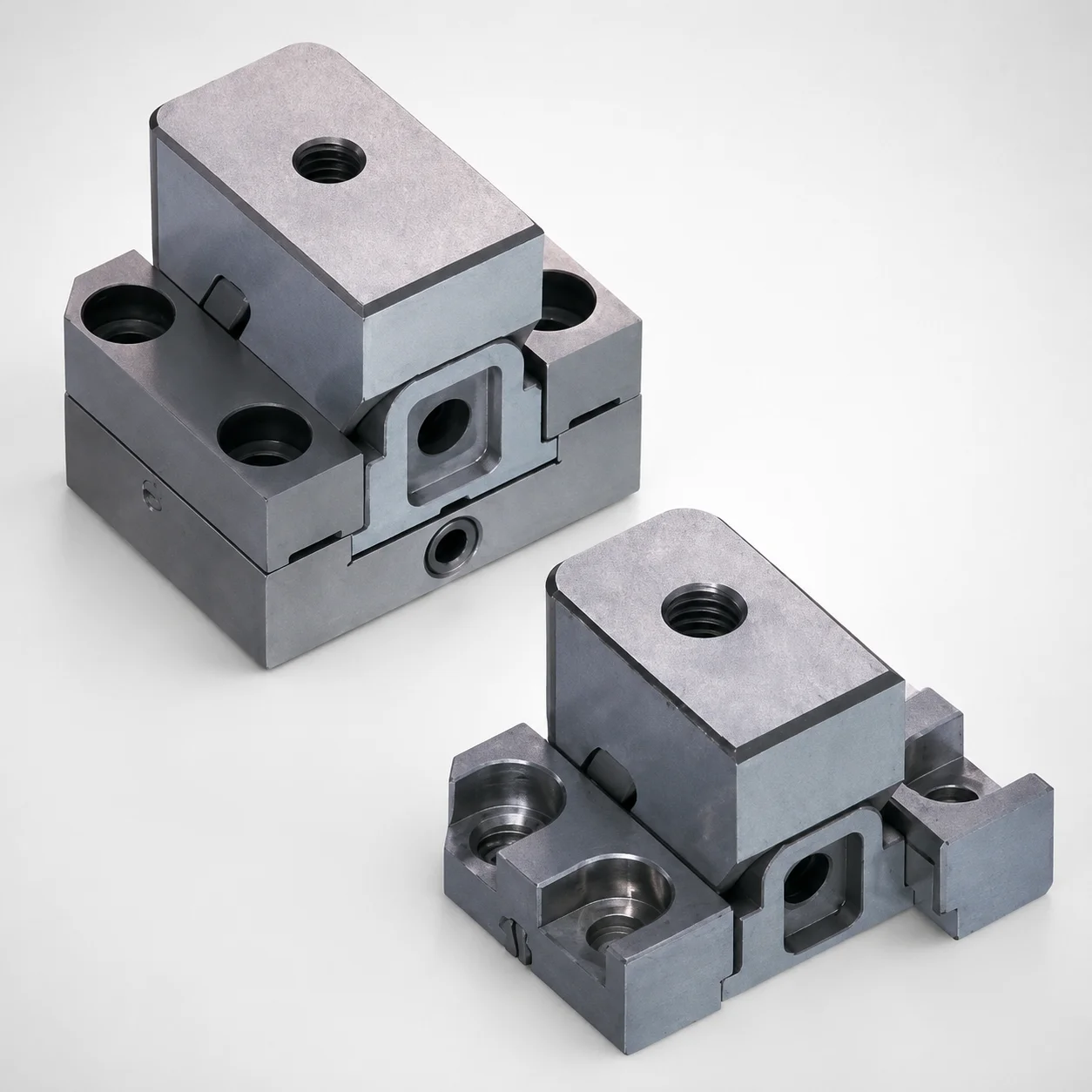
Standard Type Mini Slide Core Units
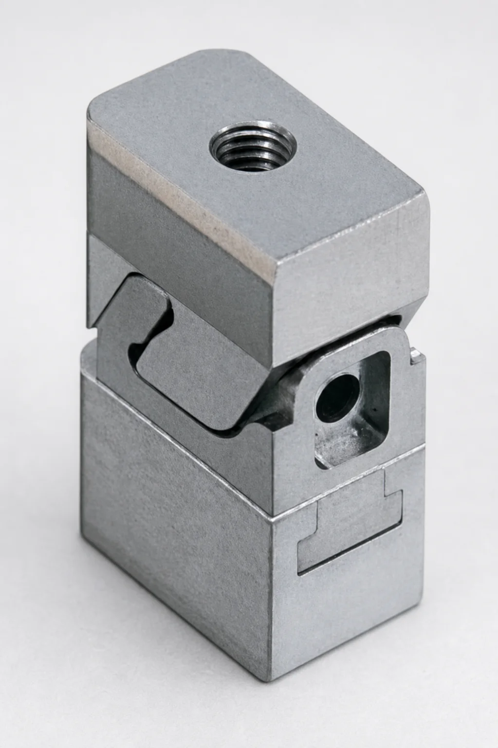
Mini Slide Core Units Slim Type (3 mm Stroke) for Inlay Tapped MSCS-Type
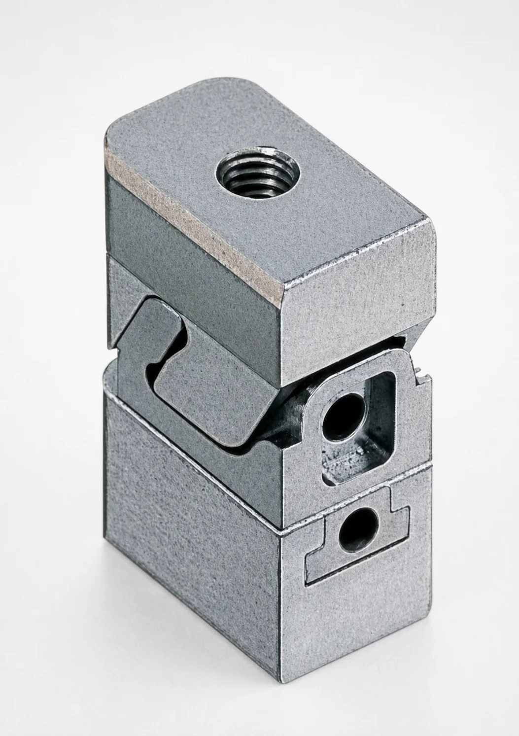
Mini Slide Core Units Slim Slide Stroke 3 mm Retractor Mechanism
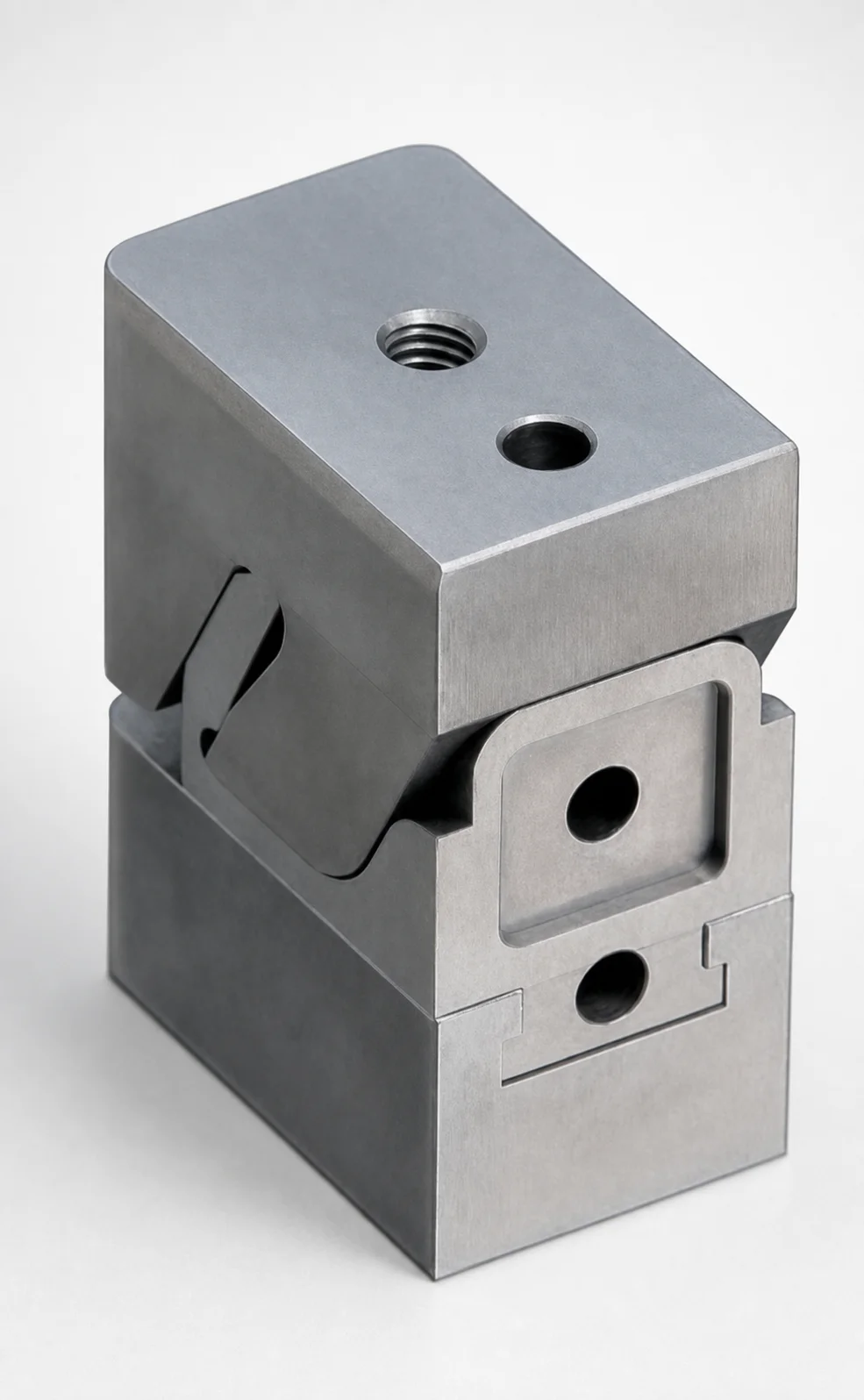
Mini Slide Core Units Slim Slide Stroke 10 mm Retracting Mechanism
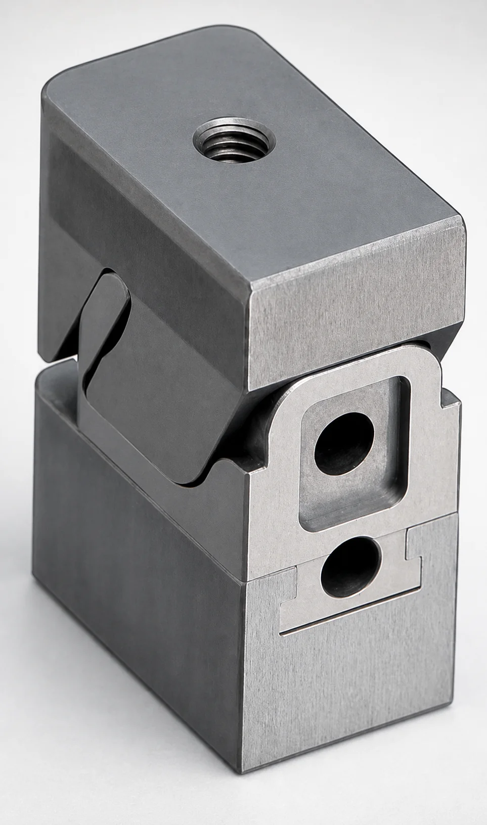
Mini Slide Core Units Slim Slide Core Retractor 6 mm Stroke
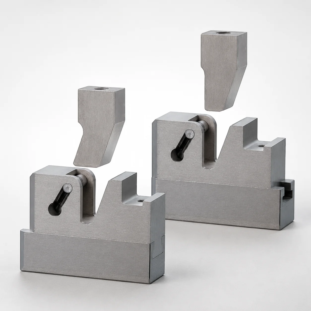
SCTM Two-Color Slide Core Units
Need Custom Specifications?
Our engineering team can help with custom configurations, material selection, and volume pricing.