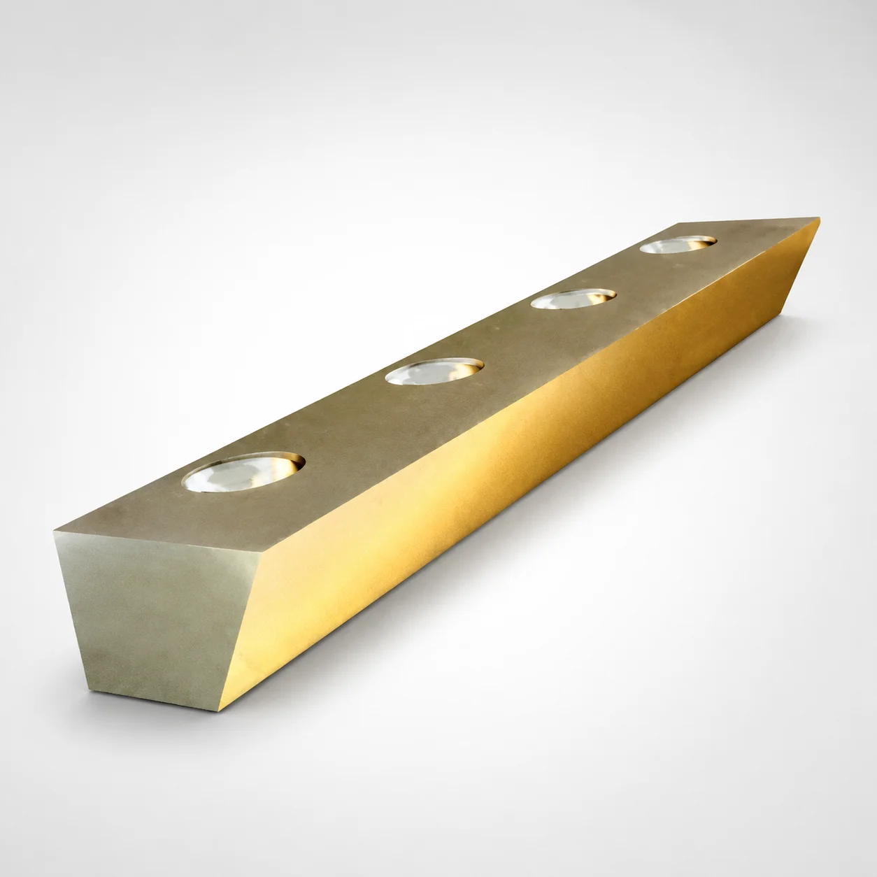
Inch Guide Rails (Bronze Plated) - No Oil Groove, 60 Degree Angle
Inch guide rails (bronze plated) from Lamina are built with a no oil groove heel configuration for cleaner sliding performance in gib rail applications. The 60 degree angle design supports stable guidance and proper alignment.
- Heel design without groove for consistent positioning in rail systems
- Bronze plated surface helps reduce friction and supports long service life
- Non-oil groove construction improves maintenance cleanliness for shop-floor use
- Used with sliding gib assemblies for tooling support and precise motion guidance
Specifications
19 configurations available
| Rail thickness (in) | Rail width (in) | Rail length (in) | Heel width (in) | Mounting hole qty. |
|---|---|---|---|---|
| 0.610 | 0.92 | 5.25 | 0.562 | 3 |
| 0.610 | 0.92 | 7.00 | 0.562 | 4 |
| 0.610 | 0.92 | 8.75 | 0.562 | 5 |
| 0.735 | 1.18 | 6.00 | 0.75 | 3 |
| 0.735 | 1.18 | 8.00 | 0.75 | 4 |
| 0.735 | 1.18 | 10.00 | 0.75 | 5 |
| 0.860 | 1.38 | 7.50 | 0.875 | 3 |
| 0.860 | 1.38 | 10.00 | 0.875 | 4 |
| 0.860 | 1.38 | 12.50 | 0.875 | 5 |
| 0.985 | 1.70 | 9.00 | 1.125 | 3 |
| 0.985 | 1.70 | 12.00 | 1.125 | 4 |
| 0.985 | 1.70 | 15.00 | 1.125 | 5 |
| 1.235 | 1.97 | 16.00 | 1.25 | 4 |
| 1.235 | 1.97 | 24.00 | 1.25 | 6 |
| 1.470 | 2.49 | 24.00 | 1.625 | 6 |
| 1.470 | 2.49 | 32.00 | 1.625 | 8 |
| 1.720 | 3.01 | 30.00 | 2.000 | 5 |
| 1.720 | 3.01 | 48.00 | 2.000 | 8 |
| 1.970 | 3.90 | 48.00 | 2.750 | 8 |
Product Guide
Application Scenarios+
This inch guide rail variant is used in precision sliding gib and guide-rail tooling where smooth, repeatable motion is required. In automotive connector or bracket mold bases, it helps maintain alignment between moving and fixed sections, supporting stable clamp/slide movement and reducing friction at the heel contact.
The no oil groove heel design is well-suited for clean-room or contamination-sensitive production, such as medical device housings, because it reduces the tendency for oil/contaminants to collect in the rail heel area while still supporting consistent positioning.
For high-cycle appliance and consumer goods molds, the bronze plated surface improves sliding behavior in gib assemblies, helping maintain fit over repeated cycles. Select the 60° angle geometry when your gib rail interface needs stable guidance and proper alignment under load.
- Use with sliding gib assemblies for motion guidance
- Choose the no-oil-heel configuration to improve maintenance cleanliness
- Apply the 60° angle to support stable alignment at the rail interface
Material & Process Details+
The provided data specifies an inch guide rail with bronze plated finish, focused on tribological performance in sliding gib assemblies. The bronze-plated contact surface is intended to reduce friction and improve wear behavior compared to unplated running surfaces under typical tool motion cycles.
For heat treatment and bulk steel grade details, the current product specifications do not list an exact grade or hardness (e.g., HRC), nor do they specify quench-and-temper, nitriding, or other heat-treatment states. As a result, material selection for critical load cases should be confirmed with your supplier documentation for the substrate steel and the plating thickness/process.
- Bronze plated finish: targeted for sliding performance and service life
- Heat-treatment state: not specified in the provided data
- Hardness/wear-vs-toughness trade-off: substrate hardness and HRC are not provided; verify for bearing/load conditions
Sizing & Selection Guide+
Select dimensions by matching your gib rail interface envelope—rail thickness, rail width, and rail length—to the cavity/core support and guide-rail seating geometry. This series provides:
- Rail thickness: 0.61 ~ 1.97 in
- Rail width: 0.92 ~ 3.9 in
- Rail length: 5.25 ~ 48 in
- Heel width: 0.562 ~ 2.75 in
Use the heel width and the required 60° angle geometry to ensure stable guidance at the contact area where alignment is established in the gib assembly.
Finally, match mounting hole quantity (3, 4, 5, 6, or 8) to your mounting plate pattern. If your rail seats into machined pockets or interfaces, ensure any clearance between the heel and mating surfaces is compatible with your design tolerances to avoid binding or excessive play during cycling.
Frequently Asked Questions
How do I choose the correct rail thickness and width for a sliding gib assembly in mold tooling?+
Use the available rail thickness range of 0.61 ~ 1.97 in and rail width range of 0.92 ~ 3.9 in to match your gib rail interface envelope and seating surfaces. Confirm that the installed rail maintains the intended guide contact area and does not interfere with the moving assembly under full stroke. The mating heel contact is also influenced by the heel width (0.562 ~ 2.75 in) and the 60° angle geometry.
What is the benefit of the no oil groove heel design when designing for cleanliness and maintenance intervals?+
This variant is built with a no oil groove heel configuration, which is intended to improve sliding cleanliness in gib rail applications. By avoiding a groove feature at the heel, it can reduce locations where oil/contaminants collect during operation. This is especially relevant for production environments where maintenance cleanliness matters, such as medical device or similar contamination-sensitive molding.
How should I select rail length to maintain alignment over the full mold movement?+
Select a rail length within 5.25 ~ 48 in so the rail supports the required guidance length across the motion path. Too short a rail can reduce the effective contact length, increasing the risk of misalignment or uneven wear. Verify that the chosen length works with your mounting plate and mounting hole layout.
How do I match the mounting hole quantity to the guide rail mounting plate design?+
This series supports mounting hole quantity options: 3, 4, 5, 6, or 8. Choose the hole count that matches your mounting plate pattern to prevent rework or additional locating features. Ensure your design allows for any required fastening clearance and maintains correct alignment with the 60° heel geometry.
Does the bronze plated finish replace the need to specify heat treatment or substrate hardness for wear-critical applications?+
The product data confirms a bronze plated surface, but it does not specify substrate steel grade, heat treatment method, or hardness (HRC). For wear-critical applications, you should verify the underlying material properties and the heat-treatment state separately from supplier documentation. This ensures you account for the full wear behavior, including the substrate toughness and hardness trade-offs, not only the plated contact surface.
Related Products
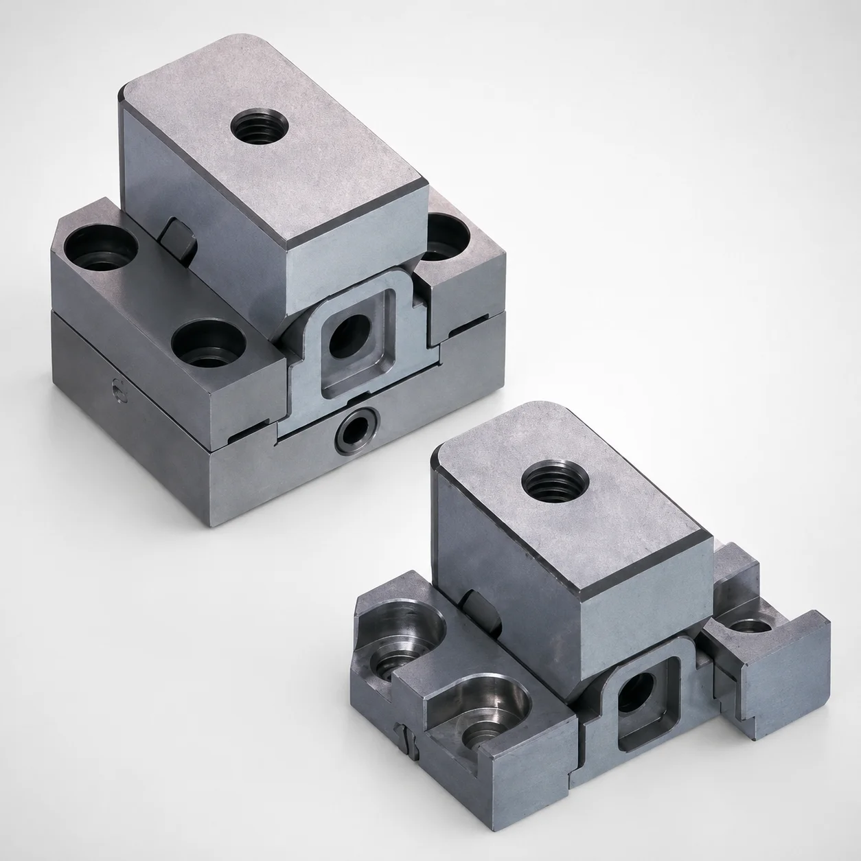
Standard Type Mini Slide Core Units
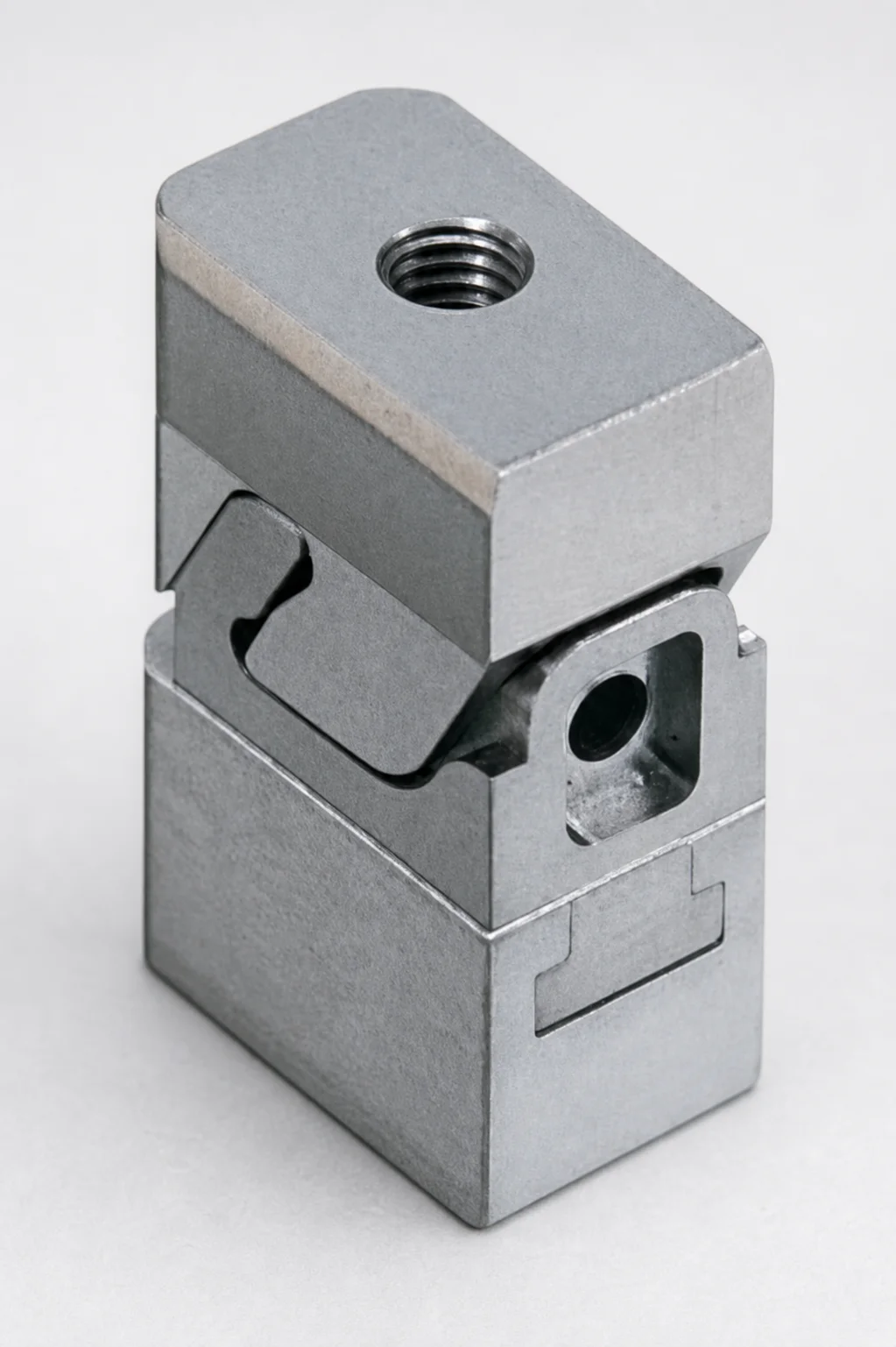
Mini Slide Core Units Slim Type (3 mm Stroke) for Inlay Tapped MSCS-Type
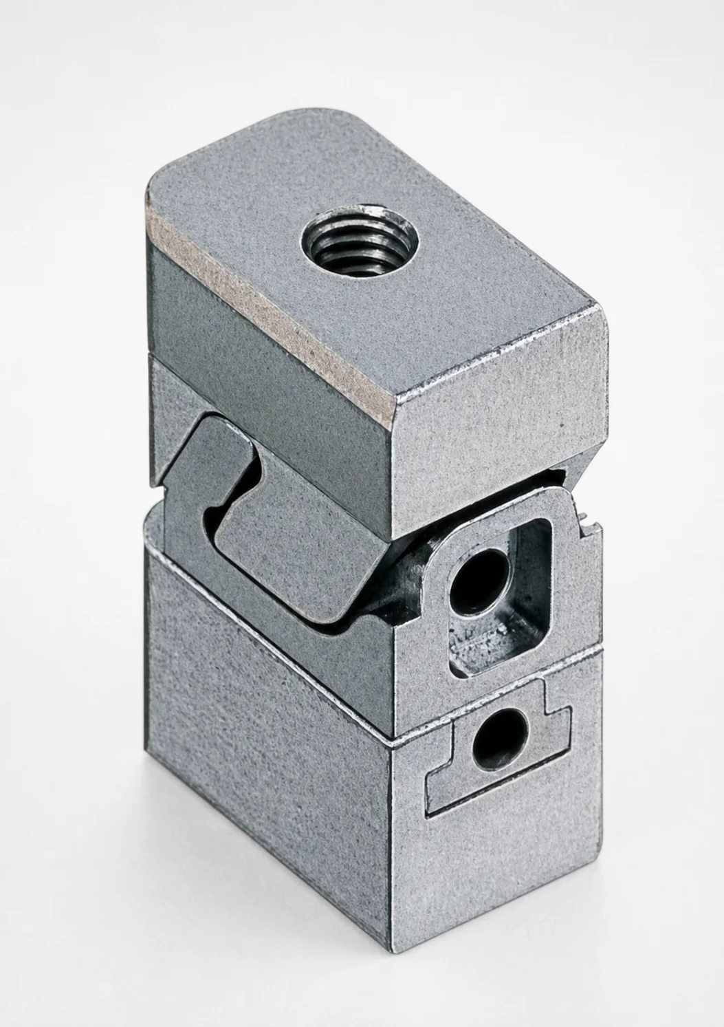
Mini Slide Core Units Slim Slide Stroke 3 mm Retractor Mechanism
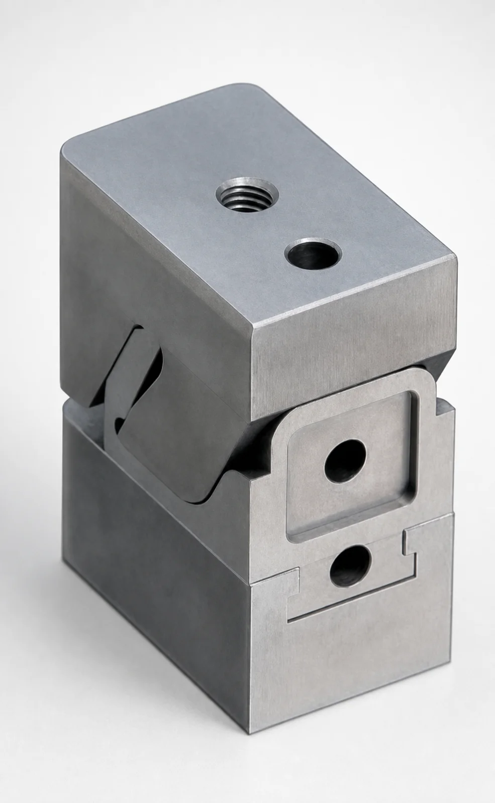
Mini Slide Core Units Slim Slide Stroke 10 mm Retracting Mechanism
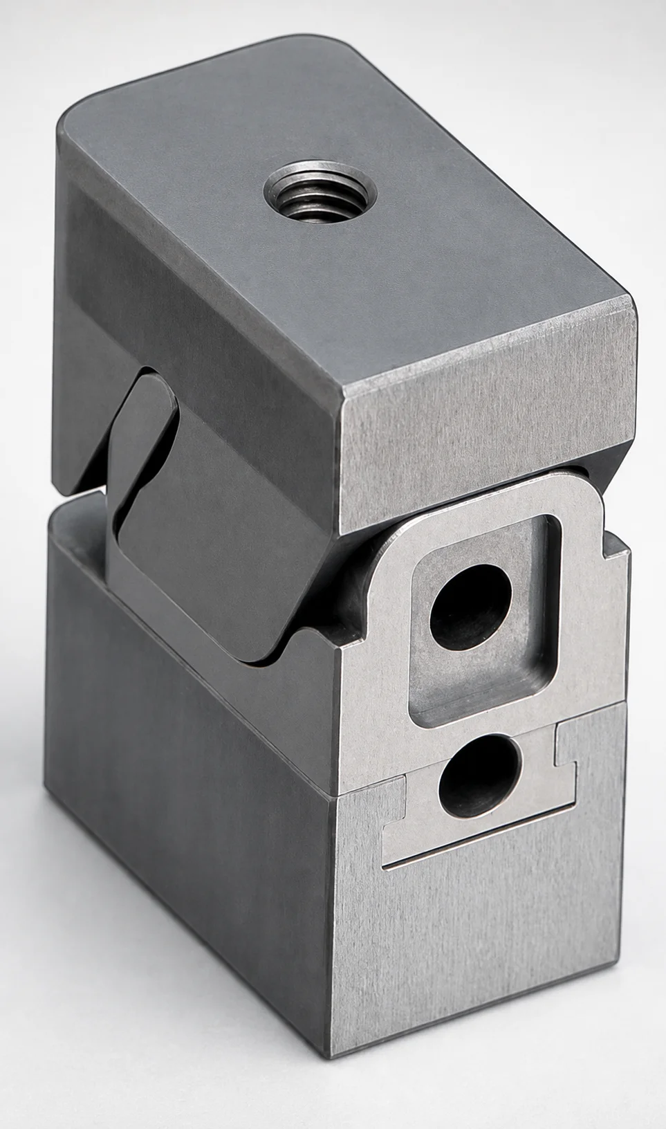
Mini Slide Core Units Slim Slide Core Retractor 6 mm Stroke
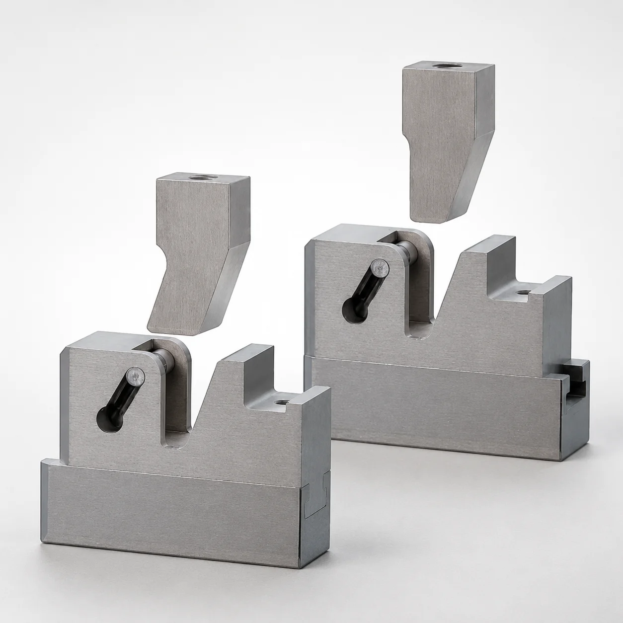
SCTM Two-Color Slide Core Units
Need Custom Specifications?
Our engineering team can help with custom configurations, material selection, and volume pricing.