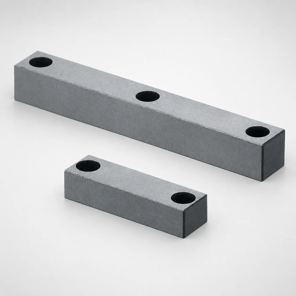
JIS Standard Steel Center Rails - Heel No Groove
Center rails heel no groove are designed for clean, non-grooved heel geometry that supports smooth linear guidance in fixture and slide assemblies. Configurable rail construction helps match different mounting layouts.
- Heel no groove design reduces interference for simplified assembly and consistent alignment
- (SKS3 or HPM2T steel) offers strong wear resistance for long-duty service
- Configurable mounting hole layouts support practical installation on common rail carriers
- Used in center rail guidance systems for machine tools, jigs, and industrial linear motion setups
Specifications
18 configurations available
| Material | Rail Thickness T (mm) | Rail Width W (mm) | Rail Length L (mm) | No. of mounting holes (pieces) | A (Bolt hole pitch) (mm) | B (Bolt hole pitch) (mm) | C (Bolt hole pitch) (mm) | D (Bolt hole pitch) (mm) | type |
|---|---|---|---|---|---|---|---|---|---|
| HPM2T | 10 ~ 30 | 12 | 40 ~ 100 | 2 | 6 ~ 94 | 16 ~ 94 | - | - | - |
| HPM2T | 10 ~ 40 | 15 | 40 ~ 100 | 2 | 6 ~ 94 | 16 ~ 94 | - | - | - |
| HPM2T | 15 ~ 50 | 20 | 40 ~ 150 | 2 | 7.5 ~ 142.5 | 20.5 ~ 142.5 | - | - | - |
| HPM2T | 10 ~ 30 | 12 | 40 ~ 100 | 3 | 6 ~ 94 | 16 ~ 94 | 26 ~ 94 | - | - |
| HPM2T | 10 ~ 40 | 15 | 40 ~ 100 | 3 | 6 ~ 94 | 16 ~ 94 | 26 ~ 94 | - | - |
| HPM2T | 15 ~ 50 | 20 | 40 ~ 150 | 3 | 7.5 ~ 142.5 | 20.5 ~ 142.5 | 33.5 ~ 142.5 | - | - |
| HPM2T | 10 ~ 30 | 12 | 40 ~ 100 | 4 | 6 ~ 94 | 16 ~ 94 | 26 ~ 94 | 36 ~ 94 | - |
| HPM2T | 10 ~ 40 | 15 | 40 ~ 100 | 4 | 6 ~ 94 | 16 ~ 94 | 26 ~ 94 | 36 ~ 94 | - |
| HPM2T | 15 ~ 50 | 20 | 40 ~ 150 | 4 | 7.5 ~ 142.5 | 20.5 ~ 142.5 | 33.5 ~ 142.5 | 46.5 ~ 142.5 | - |
| SKS3 | 10 ~ 30 | 12 | 40 ~ 100 | 2 | 6 ~ 94 | 16 ~ 94 | - | - | - |
| SKS3 | 10 ~ 40 | 15 | 40 ~ 100 | 2 | 6 ~ 94 | 16 ~ 94 | - | - | - |
| SKS3 | 15 ~ 50 | 20 | 40 ~ 150 | 2 | 7.5 ~ 142.5 | 20.5 ~ 142.5 | - | - | - |
| SKS3 | 10 ~ 30 | 12 | 40 ~ 100 | 3 | 6 ~ 94 | 16 ~ 94 | 26 ~ 94 | - | - |
| SKS3 | 10 ~ 40 | 15 | 40 ~ 100 | 3 | 6 ~ 94 | 16 ~ 94 | 26 ~ 94 | - | - |
| SKS3 | 15 ~ 50 | 20 | 40 ~ 150 | 3 | 7.5 ~ 142.5 | 20.5 ~ 142.5 | 33.5 ~ 142.5 | - | - |
| SKS3 | 10 ~ 30 | 12 | 40 ~ 100 | 4 | 6 ~ 94 | 16 ~ 94 | 26 ~ 94 | 36 ~ 94 | - |
| SKS3 | 10 ~ 40 | 15 | 40 ~ 100 | 4 | 6 ~ 94 | 16 ~ 94 | 26 ~ 94 | 36 ~ 94 | - |
| SKS3 | 15 ~ 50 | 20 | 40 ~ 150 | 4 | 7.5 ~ 142.5 | 20.5 ~ 142.5 | 33.5 ~ 142.5 | 46.5 ~ 142.5 | - |
Product Guide
Application Scenarios+
These center rails are used in injection mold tooling and industrial fixturing where stable linear motion depends on consistent guidance at the rail heel. The heel no groove geometry helps maintain clean contact surfaces, reducing interference during assembly and improving alignment retention over repeated cycles.
Common scenarios include:
- Machine tool and mold base slide assemblies: selectable rail thicknesses (T 10–30 / 10–40 / 15–50 mm) support different carrier stiffness requirements.
- Fixture and jig guidance systems: mounting-hole options (2/3/4 holes) and pitch variability (A, B, C, D ranges) enable practical retrofit to existing carriers.
- High-cycle production environments: rails made from SKS3 or HPM2T are suited to wear-prone guidance interfaces where smooth movement is required with minimal surface damage.
The configurable construction and two steel options make this variant adaptable to diverse linear-motion layouts while preserving the non-grooved heel for simplified installation and stable guidance.
Material & Process Details+
The rails are supplied in either HPM2T or SKS3 steel, selected for wear resistance in guidance applications. Both are hardened, guidance-grade steels commonly used to balance hardness with dimensional stability under sliding contact.
HPM2T is typically chosen when higher wear resistance and surface durability are priorities. SKS3 is often selected for strong wear performance with good toughness for service conditions involving vibration and intermittent loading. Exact hardness and heat-treatment details are not specified in the provided data; however, these steels are generally supplied in a hardened state suited for rails.
- Wear resistance: optimized for sliding interfaces to help limit heel-edge damage.
- Toughness trade-off: higher hardness improves wear resistance, but can reduce toughness; material selection should match the expected load severity.
- Manufacturing process: rails are manufactured to tight guidance dimensions and then heat-treated to achieve the appropriate hardness for long-duty service.
Sizing & Selection Guide+
Select rail dimensions based on the guiding surface envelope in your mold base, slide plate, or fixture carrier. This product supports the following configuration ranges: T (rail thickness) = 10–30 mm / 10–40 mm / 15–50 mm, W (rail width) = 12 / 15 / 20 mm, and L (rail length) = 40–100 mm / 40–150 mm.
To match mounting layout, choose the number of mounting holes (2, 3, or 4) and then align bolt-hole pitch dimensions to your carrier:
- A (bolt pitch) = 6–94 mm / 7.5–142.5 mm
- B = 16–94 mm / 20.5–142.5 mm
- C = 26–94 mm / 33.5–142.5 mm
- D = 36–94 mm / 46.5–142.5 mm
Ensure the selected L and hole pitch leave adequate edge distance on the carrier. Since tolerance/fit values are not provided here, confirm your carrier machining tolerances during layout to prevent misalignment during assembly, especially at the heel no groove interface.
Frequently Asked Questions
Which steel option (HPM2T vs SKS3) is more suitable for long-cycle mold base guidance rails?+
This product is offered in HPM2T or SKS3. If you expect heavy sliding wear at the heel-guidance interface, HPM2T is typically selected for higher surface durability. If your application involves more vibration or mixed loading where toughness is important, SKS3 is commonly selected for a balanced wear–toughness response.
How does the heel no groove design affect installation and alignment in slide plate assemblies?+
The heel no groove geometry is designed to reduce interference during assembly and help maintain consistent alignment. Because the heel area is non-grooved, mounting and contact behavior is simpler to reproduce across similar fixtures and carrier layouts. This is especially helpful when integrating rails into existing machine tool or mold base slide structures.
What rail thickness/width/length combinations are available for configuring a guidance layout?+
Rail thickness T is available in ranges 10–30 mm, 10–40 mm, or 15–50 mm. Rail width W is 12 / 15 / 20 mm, and rail length L is available as 40–100 mm or 40–150 mm. Match these to your carrier envelope to ensure the rail supports the required guidance stiffness.
How do I select the correct mounting hole pitch for this rail?+
Choose the number of mounting holes (2, 3, or 4) first, then select the corresponding pitch dimensions: A (6–94 mm or 7.5–142.5 mm), B (16–94 mm or 20.5–142.5 mm), C (26–94 mm or 33.5–142.5 mm), and D (36–94 mm or 46.5–142.5 mm). Confirm these pitches align with the carrier’s drilled/located features to avoid forced assembly and misalignment.
Is this rail fully configurable, or are there fixed dimensions?+
This series is described as fully configurable with selectable rail thickness (T), width (W), length (L), mounting hole count, and multiple pitch options (A/B/C/D). That means key layout dimensions can be configured to match different mounting layouts and carrier designs. However, you must select the configuration that fits your required envelope because the chosen dimensions are not interchangeable after ordering.
Related Products
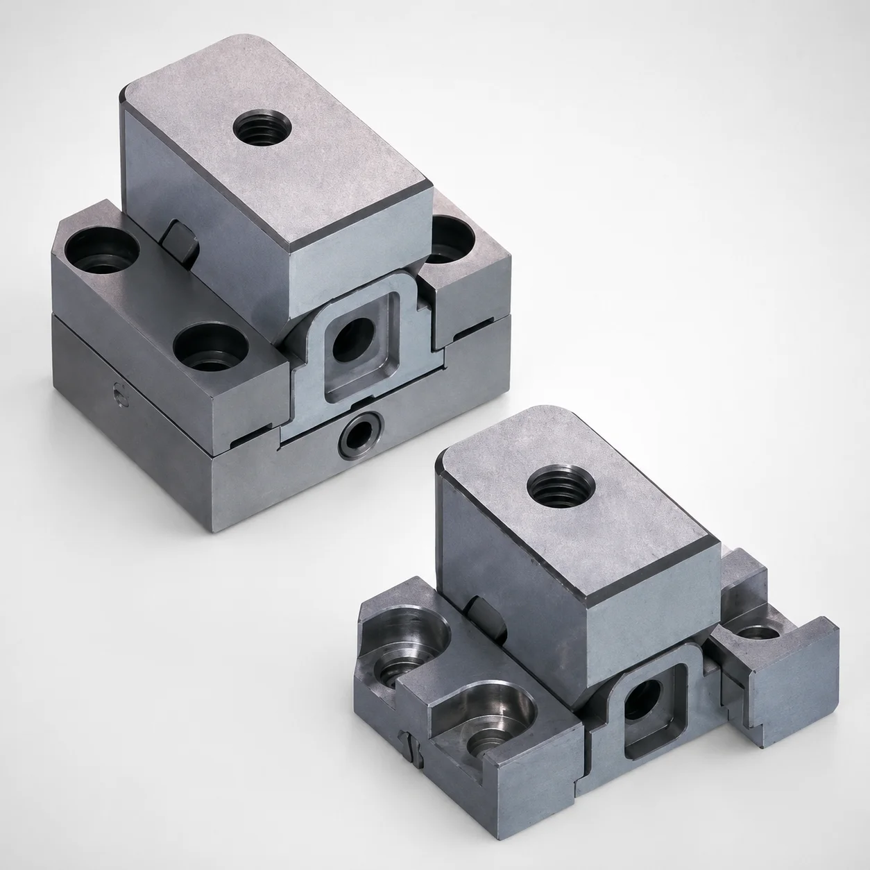
Standard Type Mini Slide Core Units
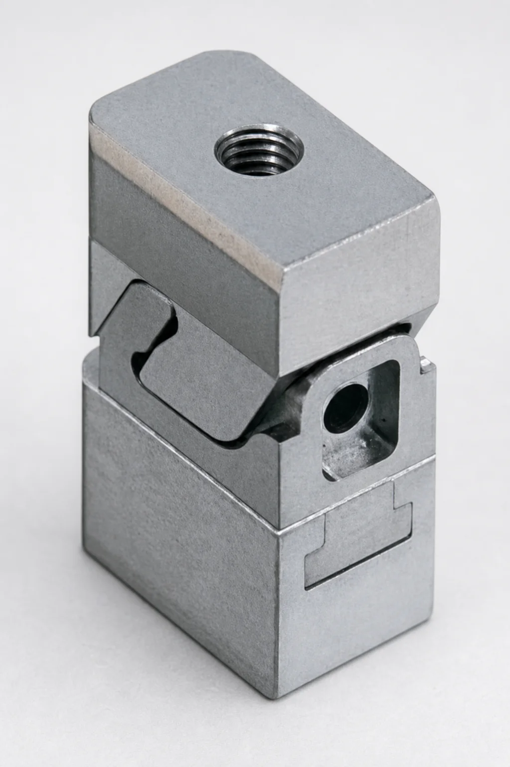
Mini Slide Core Units Slim Type (3 mm Stroke) for Inlay Tapped MSCS-Type
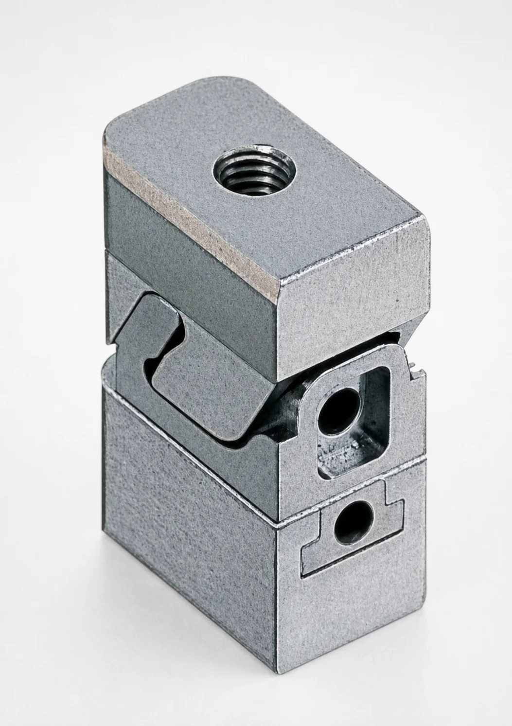
Mini Slide Core Units Slim Slide Stroke 3 mm Retractor Mechanism
Mini Slide Core Units Slim Slide Stroke 10 mm Retracting Mechanism
Mini Slide Core Units Slim Slide Core Retractor 6 mm Stroke
SCTM Two-Color Slide Core Units
Need Custom Specifications?
Our engineering team can help with custom configurations, material selection, and volume pricing.