Locating Pins
360 precision dowel pins for fixture positioning. Cylindrical, diamond, step, and spring configurations in SKD11, SUJ2, and SUS304. Tolerance grades h7, g6, m6 for press-fit and slip-fit applications.
Locating Pins — 360 Products
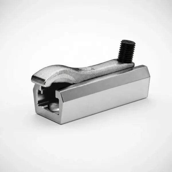
Cylindrical Locating Pins — SKD11
Standard cylindrical dowel pins. SKD11 tool steel, 58-62 HRC. Press-fit (h7) and slip-fit (g6) available.
View Details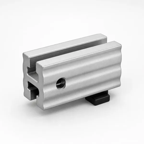
Diamond Locating Pins
Diamond-shaped cross-section for two-point contact. Accommodates thermal expansion without binding.
View Details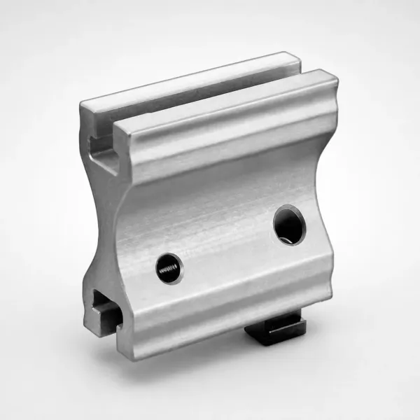
Step Locating Pins
Shouldered design with precision step for depth control. Press-fit body with guided tip for easy insertion.
View Details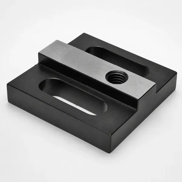
Spring Locating Pins
Spring-loaded retractable pins for automated loading/unloading. Available with ball-lock and groove-lock retention.
View DetailsLocating Pin Geometry Comparison
Four geometric configurations serve different positioning requirements:
| Geometry | Contact Type | Thermal Expansion | Best For |
|---|---|---|---|
| Cylindrical | Full circumference | Binds if ΔT is large | Primary datum pin (1 per fixture) |
| Diamond | Two-point (flat faces) | Accommodates expansion | Secondary datum pin (paired with cylindrical) |
| Step | Full circumference + shoulder | Binds if ΔT is large | Depth-controlled positioning (blind holes) |
| Spring | Full circumference (retractable) | Self-compensating | Automated load/unload stations |
Deep dive: Read Cylindrical vs Diamond Locating Pins — When to Use Each for the engineering rationale behind the 2-pin system.
How to Choose the Right Tolerance Grade
Three standard tolerance grades for locating pins:
- m6 (interference fit): Pin is slightly oversized relative to bore. Must be pressed in. Use for permanent pins that never need removal — highest positional accuracy.
- h7 (transition fit): Pin is nominally at bore size. Tight push-fit or light press-fit. Use for semi-permanent pins that may need replacement during fixture maintenance.
- g6 (clearance fit): Pin is slightly undersized. Slides freely in bore. Use for removable pins (spring pins, retractable locators) or where thermal expansion must be accommodated.
Interference fit formula: For a Ø10 m6 pin in an H7 bore, the interference range is +0.001 to +0.024 mm. Required press-in force ≈ π × d × L × μ × p, where μ ≈ 0.15 (steel-on-steel) and p = interference × E / (2 × d).
Learn more: See How to Calculate Interference Fit for Press-Fit Locating Pins for formulas and worked examples.
Pin-Bushing Pairing Reference
Locating pins achieve their best performance when paired with the correct bushing:
| Pin Tolerance | Bushing Bore | Fit Type | Application |
|---|---|---|---|
| m6 (pin) + H7 (bushing) | H7 | Light interference | Permanent datum pins in hardened fixture plates |
| h7 (pin) + H7 (bushing) | H7 | Transition (slight clearance to light interference) | Semi-permanent pins, maintainable fixtures |
| g6 (pin) + H7 (bushing) | H7 | Clearance (0.005–0.024 mm gap at Ø10) | Retractable pins, spring locators, thermal compensation |
Deep dive: Read How to Pair Locating Pins with Bushings for Optimal Fixture Accuracy for complete tolerance matching tables.
Pin-Bushing Pairing Quick Reference
Match your locating pin tolerance grade to the correct bushing bore for optimal fit:
Deep dive: See How to Pair Locating Pins with Bushings for Optimal Fixture Accuracy for clearance values by diameter, material pairing rules, and replacement indicators.
Specification Quick Reference
Standard locating pin dimensions available across all geometry types:
| Diameter (mm) | Available Lengths (mm) | Geometries | Tolerances |
|---|---|---|---|
| Ø3 – Ø5 | 10, 15, 20, 25, 30 | Cylindrical, Step | h7, g6 |
| Ø6 – Ø8 | 15, 20, 25, 30, 40, 50 | Cylindrical, Diamond, Step, Spring | h7, g6, m6 |
| Ø10 – Ø12 | 20, 25, 30, 40, 50, 60, 80 | Cylindrical, Diamond, Step, Spring | h7, g6, m6 |
| Ø16 – Ø20 | 25, 30, 40, 50, 60, 80, 100 | Cylindrical, Diamond, Step | h7, g6, m6 |
| Ø25 – Ø30 | 30, 40, 50, 60, 80, 100 | Cylindrical, Diamond | h7, m6 |
Materials available per diameter: SKD11 (all sizes), SUJ2 (Ø3–Ø25), SUS304 (Ø6–Ø20). Custom diameters and lengths available on request.
Application Scenarios
CNC Machining Fixtures
Pain point: Workpiece must return to the same position within ±0.01 mm after each unload/reload cycle.
Why it fits: A cylindrical + diamond pin pair in SKD11 (58-62 HRC) provides repeatable X-Y-θ positioning with 0.005 mm repeatability over millions of cycles.
Recommended: Cylindrical (m6) + Diamond (h7), SKD11
Inspection Gauges
Pain point: Gauge accuracy degrades as locating pins wear, causing false pass/fail readings.
Why it fits: SUJ2 bearing steel pins offer superior surface finish and roundness, maintaining gauge accuracy longer than standard tool steel.
Recommended: Cylindrical (m6), SUJ2
Automated Assembly
Pain point: Fixed pins require manual part loading — slows cycle time and risks operator injury.
Why it fits: Spring-loaded retractable pins allow automated part placement: pin retracts during load, extends to locate after placement, retracts again for unload.
Recommended: Spring Locating Pins (g6), ball-lock retention
Quick Specification Lookup
Standard diameter range: Ø2 mm to Ø25 mm in 0.5 mm increments. Lengths: 10 mm to 100 mm.
| Diameter | h7 Tolerance | g6 Tolerance | m6 Tolerance |
|---|---|---|---|
| Ø4 | 4.000 / 3.990 | 3.992 / 3.984 | 4.008 / 4.002 |
| Ø6 | 6.000 / 5.990 | 5.992 / 5.984 | 6.012 / 6.004 |
| Ø8 | 8.000 / 7.985 | 7.991 / 7.981 | 8.015 / 8.006 |
| Ø10 | 10.000 / 9.985 | 9.991 / 9.981 | 10.015 / 10.006 |
| Ø12 | 12.000 / 11.982 | 11.989 / 11.978 | 12.018 / 12.007 |
| Ø16 | 16.000 / 15.982 | 15.989 / 15.978 | 16.018 / 16.007 |
| Ø20 | 20.000 / 19.979 | 19.987 / 19.974 | 20.021 / 20.008 |
Engineering Resources
Application Scenarios
Precision CNC Fixture Datum Setup
Pain point: Manual workpiece alignment takes 15-20 minutes per setup and introduces operator-dependent positional variation of ±0.1 mm.
Why it fits: Press-fit cylindrical pins (m6) establish permanent datum points — setup drops to under 2 minutes with ±0.005 mm repeatability.
Multi-Cavity Mold Fixture Plates
Pain point: Large fixture plates for multi-cavity molds need precise alignment but thermal expansion causes binding in tight-fitting pins.
Why it fits: Diamond locating pins allow thermal expansion along one axis while constraining the other, eliminating over-constraint in 2-pin systems.
Quick-Change Fixture Systems
Pain point: Frequent product changeovers require fixture components that can be rapidly installed and removed without compromising positioning accuracy.
Why it fits: Spring-loaded retractable locating pins (g6 clearance fit) allow push-button insertion and extraction while maintaining ±0.01 mm positioning.
Frequently Asked Questions
What tolerance grades are available for locating pins (h7, g6, m6)?+
What is the difference between cylindrical, diamond, and step locating pins?+
What bushing should I pair with my locating pin for optimal fit?+
Can I order locating pins with custom lengths or tip configurations?+
How do I calculate the correct interference fit for a press-fit locating pin?+
Why do I need a diamond pin with a round pin?+
How do I extend the service life of locating pins?+
Related Product Categories
Need Locating Pins?
Specify diameter, length, material, and tolerance grade. We'll provide a quote within 24 hours.