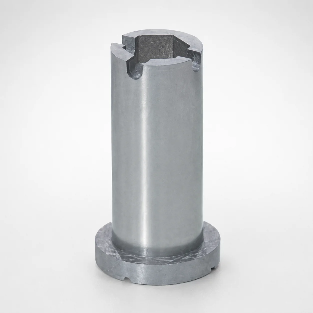
Runner Flow Direction Change Pins for Z Pins
Runner Flow Direction Change Pins for Z Pins are engineered to maintain stable alignment when changing runner flow direction setups. The configurable-length design helps support smooth transitions and consistent machine performance in production environments.
- Ensures reliable positioning during component alignment for flow direction change
- Durable construction helps minimize wear on precision mold and machine parts
- Configurable length supports different Z-pin runner layouts and assembly needs
- Built for industrial automation use to reduce downtime and protect sensitive systems
Specifications
144 configurations available
| Tip Shape | Dimension designation type | D (Outer diameter) (mm) | A (Groove width, Runner groove, Shape A) (mm) | B (Semicircle, Runner groove, Shape B) (mm) | C (Virtual circle diameter, Runner groove, Shape C) (mm) | F (Ejector pin guide length) (mm) | L (L dimension) (mm) | LC (L dimension alteration) (mm) | P (Inner diameter) (mm) | type |
|---|---|---|---|---|---|---|---|---|---|---|
| I | L dimension designation | 8 | - | 1 ~ 1.5 | - | 7 ~ 30 | 15 ~ 50 | - | 3 | - |
| I | L dimension designation | 8 | - | - | 2 | 7 ~ 30 | 15 ~ 50 | - | 3 | - |
| K | L dimension designation | 8 | - | 1 ~ 1.5 | - | 7 ~ 30 | 15 ~ 50 | - | 3 | - |
| K | L dimension designation | 8 | - | - | 2 | 7 ~ 30 | 15 ~ 50 | - | 3 | - |
| L | L dimension designation | 8 | - | 1 ~ 1.5 | - | 7 ~ 30 | 15 ~ 50 | - | 3 | - |
| L | L dimension designation | 8 | - | - | 2 | 7 ~ 30 | 15 ~ 50 | - | 3 | - |
| N | L dimension designation | 8 | - | - | - | 7 ~ 30 | 15 ~ 50 | - | 3 | - |
| T | L dimension designation | 8 | - | 1 ~ 1.5 | - | 7 ~ 30 | 15 ~ 50 | - | 3 | - |
| T | L dimension designation | 8 | - | - | 2 | 7 ~ 30 | 15 ~ 50 | - | 3 | - |
| I | L dimension designation | 10 | 3 | - | - | 7 ~ 30 | 15 ~ 50 | - | 4 | - |
| I | L dimension designation | 10 | - | 1 ~ 2.5 | - | 7 ~ 30 | 15 ~ 50 | - | 4 | - |
| I | L dimension designation | 10 | - | - | 2 ~ 2.5 | 7 ~ 30 | 15 ~ 50 | - | 4 | - |
| K | L dimension designation | 10 | 3 | - | - | 7 ~ 30 | 15 ~ 50 | - | 4 | - |
| K | L dimension designation | 10 | - | 1 ~ 2.5 | - | 7 ~ 30 | 15 ~ 50 | - | 4 | - |
| K | L dimension designation | 10 | - | - | 2 ~ 2.5 | 7 ~ 30 | 15 ~ 50 | - | 4 | - |
| L | L dimension designation | 10 | 3 | - | - | 7 ~ 30 | 15 ~ 50 | - | 4 | - |
| L | L dimension designation | 10 | - | 1 ~ 2.5 | - | 7 ~ 30 | 15 ~ 50 | - | 4 | - |
| L | L dimension designation | 10 | - | - | 2 ~ 2.5 | 7 ~ 30 | 15 ~ 50 | - | 4 | - |
| N | L dimension designation | 10 | - | - | - | 7 ~ 30 | 15 ~ 50 | - | 4 | - |
| T | L dimension designation | 10 | 3 | - | - | 7 ~ 30 | 15 ~ 50 | - | 4 | - |
| T | L dimension designation | 10 | - | 1 ~ 2.5 | - | 7 ~ 30 | 15 ~ 50 | - | 4 | - |
| T | L dimension designation | 10 | - | - | 2 ~ 2.5 | 7 ~ 30 | 15 ~ 50 | - | 4 | - |
| I | L dimension designation | 13 | 3 ~ 4 | - | - | 7 ~ 30 | 20 ~ 60 | - | 5 ~ 6 | - |
| I | L dimension designation | 13 | - | 1 ~ 3 | - | 7 ~ 30 | 20 ~ 60 | - | 5 ~ 6 | - |
| I | L dimension designation | 13 | - | - | 2 ~ 3 | 7 ~ 30 | 20 ~ 60 | - | 5 ~ 6 | - |
| K | L dimension designation | 13 | 3 ~ 4 | - | - | 7 ~ 30 | 20 ~ 60 | - | 5 ~ 6 | - |
| K | L dimension designation | 13 | - | 1 ~ 2.5 | - | 7 ~ 30 | 20 ~ 60 | - | 5 ~ 6 | - |
| K | L dimension designation | 13 | - | - | 2 ~ 3 | 7 ~ 30 | 20 ~ 60 | - | 5 ~ 6 | - |
| L | L dimension designation | 13 | 3 ~ 4 | - | - | 7 ~ 30 | 20 ~ 60 | - | 5 ~ 6 | - |
| L | L dimension designation | 13 | - | 1 ~ 3 | - | 7 ~ 30 | 20 ~ 60 | - | 5 ~ 6 | - |
| L | L dimension designation | 13 | - | - | 2 ~ 3 | 7 ~ 30 | 20 ~ 60 | - | 5 ~ 6 | - |
| N | L dimension designation | 13 | - | - | - | 7 ~ 30 | 20 ~ 60 | - | 5 ~ 6 | - |
| T | L dimension designation | 13 | 3 ~ 4 | - | - | 7 ~ 30 | 20 ~ 60 | - | 5 ~ 6 | - |
| T | L dimension designation | 13 | - | 1 ~ 2.5 | - | 7 ~ 30 | 20 ~ 60 | - | 5 ~ 6 | - |
| T | L dimension designation | 13 | - | - | 2 ~ 3 | 7 ~ 30 | 20 ~ 60 | - | 5 ~ 6 | - |
| I | L dimension designation | 16 | 3 ~ 6 | - | - | 7 ~ 30 | 20 ~ 60 | - | 8 | - |
| I | L dimension designation | 16 | - | 1 ~ 4 | - | 7 ~ 30 | 20 ~ 60 | - | 8 | - |
| I | L dimension designation | 16 | - | - | 2 ~ 4 | 7 ~ 30 | 20 ~ 60 | - | 8 | - |
| K | L dimension designation | 16 | 3 ~ 4 | - | - | 7 ~ 30 | 20 ~ 60 | - | 8 | - |
| K | L dimension designation | 16 | - | 1 ~ 2.5 | - | 7 ~ 30 | 20 ~ 60 | - | 8 | - |
| K | L dimension designation | 16 | - | - | 2 ~ 3 | 7 ~ 30 | 20 ~ 60 | - | 8 | - |
| L | L dimension designation | 16 | 3 ~ 6 | - | - | 7 ~ 30 | 20 ~ 60 | - | 8 | - |
| L | L dimension designation | 16 | - | 1 ~ 4 | - | 7 ~ 30 | 20 ~ 60 | - | 8 | - |
| L | L dimension designation | 16 | - | - | 2 ~ 4 | 7 ~ 30 | 20 ~ 60 | - | 8 | - |
| N | L dimension designation | 16 | - | - | - | 7 ~ 30 | 20 ~ 60 | - | 8 | - |
| T | L dimension designation | 16 | 3 ~ 4 | - | - | 7 ~ 30 | 20 ~ 60 | - | 8 | - |
| T | L dimension designation | 16 | - | 1 ~ 2.5 | - | 7 ~ 30 | 20 ~ 60 | - | 8 | - |
| T | L dimension designation | 16 | - | - | 2 ~ 3 | 7 ~ 30 | 20 ~ 60 | - | 8 | - |
| I | L dimension selection | 8 | - | 1 ~ 1.5 | - | - | 20 ~ 50 | - | 3 | - |
| I | L dimension selection | 8 | - | 1 ~ 1.5 | - | - | - | 20 ~ 49.9 | 3 | - |
Product Guide
Application Scenarios+
This runner flow direction change pin is used inside sprue/runner tooling to hold precise alignment when a runner transitions to a new flow direction (Z-pin based runner layouts). By maintaining positional repeatability at the changeover area, it helps prevent misalignment that can lead to gate/runner mismatches and flow imbalance.
- Automotive connector and small-part molds: Suitable where multiple runner segments require consistent shutoff and alignment during part-to-part repetition. The configurable length range (ejector guide length F = 7–30 mm) supports different Z-pin runner assemblies while keeping the direction change stable.
- Consumer electronics and housings: Helps reduce flow disruption during runner redirection, which supports uniform filling for thin-wall features and fine inserts. Compatible tip shapes (I, K, L, N, T) allow matching to groove geometry in the runner change zone.
- Industrial automation housings with high cycle demands: Provides durable guidance for repeatable alignment, supporting smoother production operation and lowering the risk of downtime from cumulative runner misalignment.
Material & Process Details+
The provided product metadata does not specify a steel grade, heat-treatment state, or hardness (HRC). As a result, Axiom Molds can only describe material properties at the level of what is supported by the listing: the component is offered in multiple dimensional variants (tip shapes and groove-related diameters) intended for precision alignment in runner-change tooling.
For runner components and guide pins, suppliers typically select steels optimized for wear resistance and dimensional stability, then apply heat treatment such as quenching & tempering or nitriding depending on the load and sliding conditions. However, because no specific grade (e.g., SKD61/H13, SKH51/M2) is stated here, hardness and wear–toughness trade-offs (e.g., higher hardness improving wear at the expense of toughness) cannot be confirmed for this exact variant.
Sizing & Selection Guide+
To select the correct runner flow direction change pin, match its geometry to the runner groove change design and the Z-pin assembly envelope. Choose the outer diameter D first (8, 10, 13, 16 mm) so the pin fits the corresponding guide/retention feature in your mold base.
- Tip/groove compatibility: Select the tip shape (I, K, L, N, T) and the groove-related dimensions A, B, and C (A: 3 / 3–4 / 3–6 mm; B: 1–1.5 / 1–2.5 / 1–3 / 1–4 mm; C: 2 / 2–2.5 / 2–3 / 2–4 mm) to match the runner groove profile at the flow direction change.
- Length and guidance: Use the fixed ejector pin guide length F = 7–30 mm and select the L variant from 15–50, 20–60, 20–50, or 30–60 mm depending on available assembly space. For alignment sequencing, confirm LC = 20–49.9 or 20–59.9 mm against your layout.
- Inner diameter P: Ensure P = 3, 4, 5–6, or 8 mm fits the mating Z-pin/runner interface.
Tolerance and fit are not specified in the listing; confirm clearance requirements with your mold design drawings and the mating part’s tolerances.
Frequently Asked Questions
Which tip shape (I, K, L, N, T) should I choose for a specific runner groove change geometry?+
Use the tip shape that matches your runner groove profile at the flow direction change zone. In this series, compatibility is tied to the selected groove-related dimensions: A (3 / 3–4 / 3–6 mm), B (1–1.5 / 1–2.5 / 1–3 / 1–4 mm), and C (2 / 2–2.5 / 2–3 / 2–4 mm). Select a tip shape and A/B/C combination that replicates the intended runner channel cross-section.
How do I ensure the pin length will fit my Z-pin runner layout?+
First confirm the fixed ejector pin guide length range F = 7–30 mm. Then choose the appropriate L range from 15–50, 20–60, 20–50, or 30–60 mm based on the available mold assembly space. If your drawing uses an additional alignment offset, verify the LC selection: 20–49.9 or 20–59.9 mm.
What outer diameter D options are available, and how should I match them to my mold guide features?+
This series provides D = 8, 10, 13, or 16 mm. Match the pin’s outer diameter to the corresponding guide bore/retention feature in your mold base so the runner-change pin can seat and locate correctly. Since tolerances are not listed here, verify clearance and press/fit requirements using your own drawing tolerances.
How do A, B, and C affect runner flow direction change alignment?+
A, B, and C describe the runner groove-related geometry used at the direction-change interface. Choose values that reflect the groove profile you designed for the runner channel: A (3 to 3–6 mm), B (1 to 1–4 mm), and C (2 to 2–4 mm). Correct selection helps prevent step discontinuities at the changeover that can destabilize flow and increase sensitivity to misalignment.
What inner diameter P values are available for mating with the Z-pin interface?+
The inner diameter options are P = 3, 4, 5–6, or 8 mm. Select P based on the mating Z-pin or interface size in your runner-change assembly. If your assembly includes multiple constraints (guide bore, clearance, and alignment), confirm P selection together with D and the selected length ranges (F/L/LC).
Related Products
Need Custom Specifications?
Our engineering team can help with custom configurations, material selection, and volume pricing.