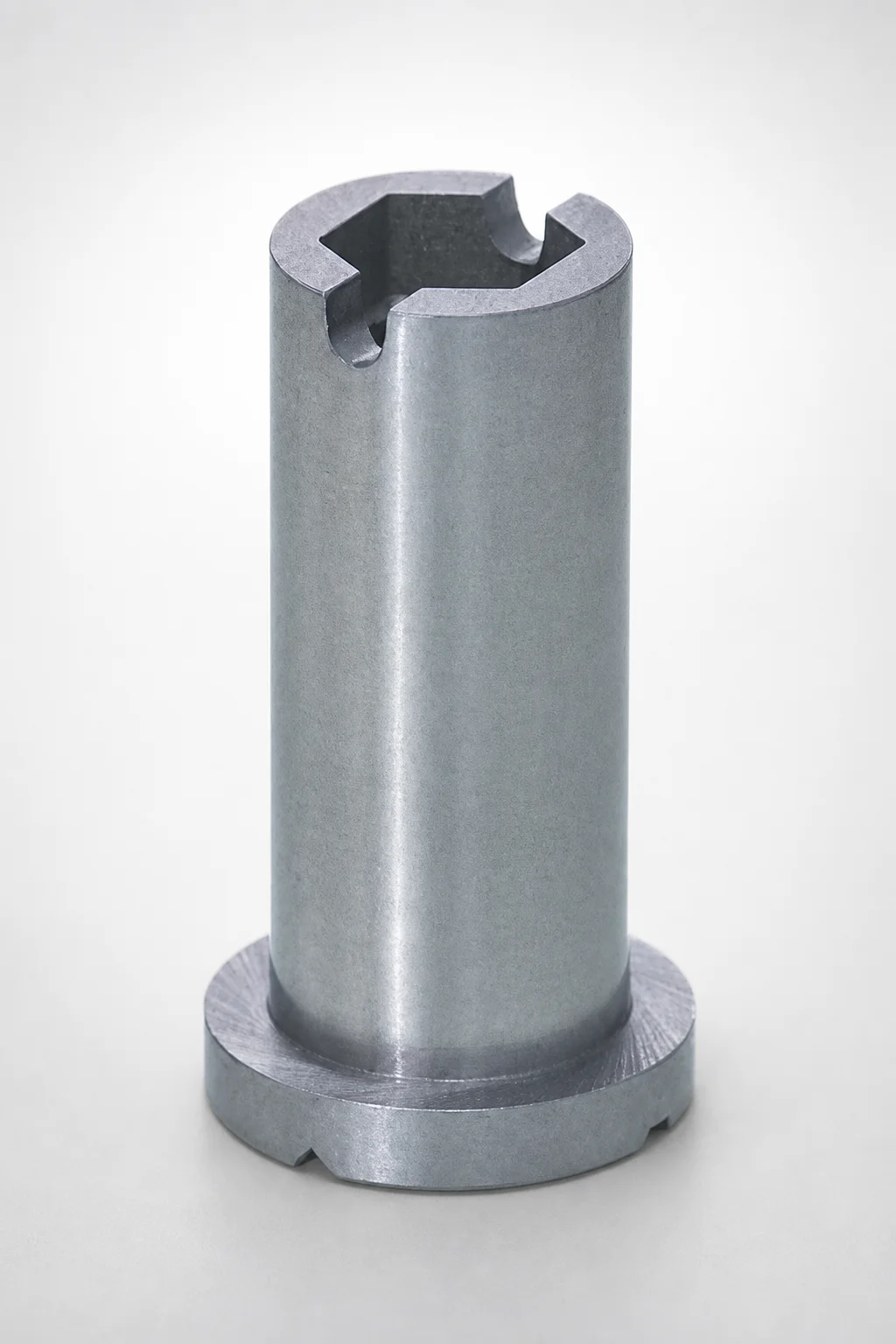
RCPL Runner Flow Direction Change Pins for Ejector Pins
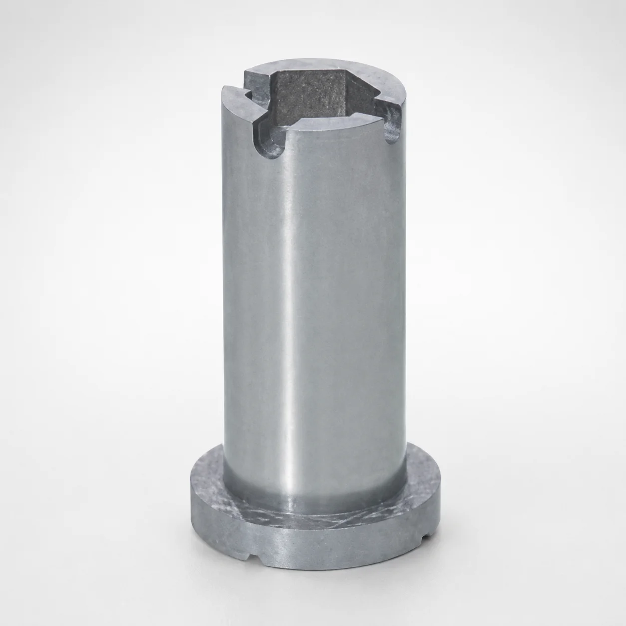
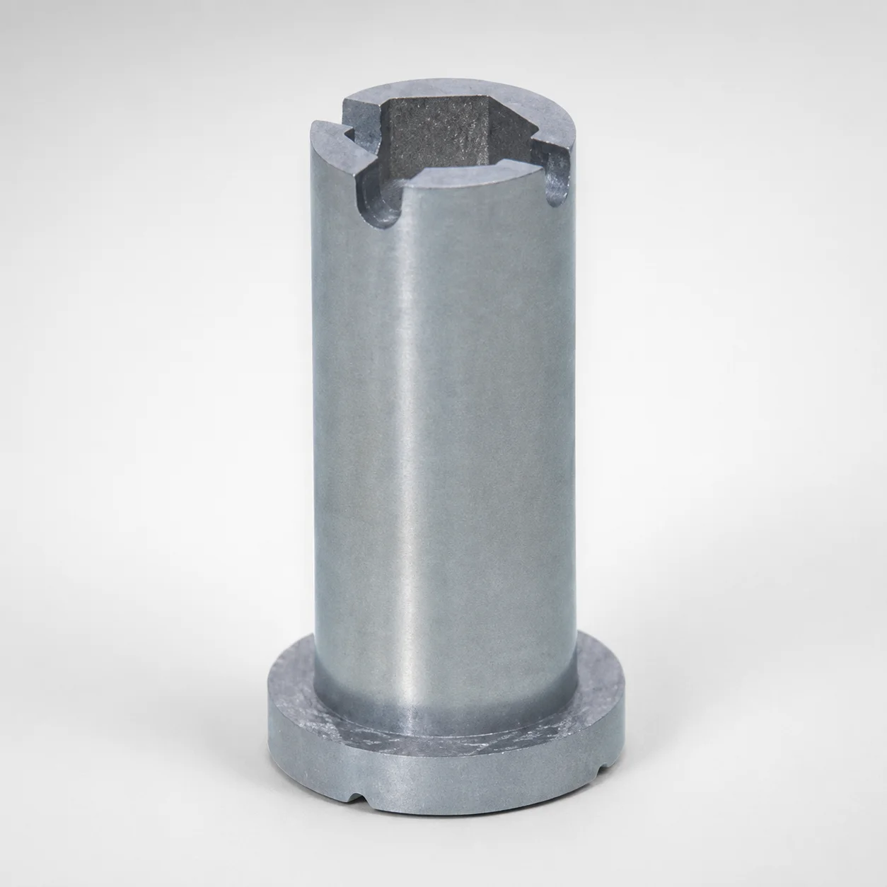
Runner flow direction change pins for ejector pins (RCPL) provide a reliable way to introduce and switch runner flow directions in mold assemblies. The configurable length helps you match the pin placement to your layout while maintaining consistent guidance.
- Runner groove design supports controlled flow direction changes in the mold
- (RCPL) configuration for stable pin guidance with ejector pin integration
- Configurable length selection to fit different mold runner geometries
- Designed for common die and runner applications in injection molding
Specifications
144 configurations available
| Tip Shape | Dimension designation type | D (Outer diameter) (mm) | A (Groove width, Runner groove, Shape A) (mm) | B (Semicircle, Runner groove, Shape B) (mm) | C (Virtual circle diameter, Runner groove, Shape C) (mm) | F (Ejector pin guide length) (mm) | G (Taper angle) (mm) | L (L dimension) (mm) | LC (L dimension alteration) (mm) | P (Inner diameter) (mm) | type |
|---|---|---|---|---|---|---|---|---|---|---|---|
| I | L dimension designation | 8 | - | 1 ~ 1.5 | - | 8 ~ 30 | 0 ~ 5 | 15 ~ 50 | - | 3 | - |
| I | L dimension designation | 8 | - | - | 2 | 8 ~ 30 | 0 ~ 5 | 15 ~ 50 | - | 3 | - |
| K | L dimension designation | 8 | - | 1 ~ 1.5 | - | 8 ~ 30 | 0 ~ 5 | 15 ~ 50 | - | 3 | - |
| K | L dimension designation | 8 | - | - | 2 | 8 ~ 30 | 0 ~ 5 | 15 ~ 50 | - | 3 | - |
| L | L dimension designation | 8 | - | 1 ~ 1.5 | - | 8 ~ 30 | 0 ~ 5 | 15 ~ 50 | - | 3 | - |
| L | L dimension designation | 8 | - | - | 2 | 8 ~ 30 | 0 ~ 5 | 15 ~ 50 | - | 3 | - |
| N | L dimension designation | 8 | - | - | - | 8 ~ 30 | 0 ~ 5 | 15 ~ 50 | - | 3 | - |
| T | L dimension designation | 8 | - | 1 ~ 1.5 | - | 8 ~ 30 | 0 ~ 5 | 15 ~ 50 | - | 3 | - |
| T | L dimension designation | 8 | - | - | 2 | 8 ~ 30 | 0 ~ 5 | 15 ~ 50 | - | 3 | - |
| I | L dimension designation | 10 | 3 | - | - | 8 ~ 30 | 0 ~ 5 | 15 ~ 50 | - | 4 | - |
| I | L dimension designation | 10 | - | 1 ~ 2.5 | - | 8 ~ 30 | 0 ~ 5 | 15 ~ 50 | - | 4 | - |
| I | L dimension designation | 10 | - | - | 2 ~ 2.5 | 8 ~ 30 | 0 ~ 5 | 15 ~ 50 | - | 4 | - |
| K | L dimension designation | 10 | 3 | - | - | 8 ~ 30 | 0 ~ 5 | 15 ~ 50 | - | 4 | - |
| K | L dimension designation | 10 | - | 1 ~ 2.5 | - | 8 ~ 30 | 0 ~ 5 | 15 ~ 50 | - | 4 | - |
| K | L dimension designation | 10 | - | - | 2 ~ 2.5 | 8 ~ 30 | 0 ~ 5 | 15 ~ 50 | - | 4 | - |
| L | L dimension designation | 10 | 3 | - | - | 8 ~ 30 | 0 ~ 5 | 15 ~ 50 | - | 4 | - |
| L | L dimension designation | 10 | - | 1 ~ 2.5 | - | 8 ~ 30 | 0 ~ 5 | 15 ~ 50 | - | 4 | - |
| L | L dimension designation | 10 | - | - | 2 ~ 2.5 | 8 ~ 30 | 0 ~ 5 | 15 ~ 50 | - | 4 | - |
| N | L dimension designation | 10 | - | - | - | 8 ~ 30 | 0 ~ 5 | 15 ~ 50 | - | 4 | - |
| T | L dimension designation | 10 | 3 | - | - | 8 ~ 30 | 0 ~ 5 | 15 ~ 50 | - | 4 | - |
| T | L dimension designation | 10 | - | 1 ~ 2.5 | - | 8 ~ 30 | 0 ~ 5 | 15 ~ 50 | - | 4 | - |
| T | L dimension designation | 10 | - | - | 2 ~ 2.5 | 8 ~ 30 | 0 ~ 5 | 15 ~ 50 | - | 4 | - |
| I | L dimension designation | 13 | 3 ~ 4 | - | - | 10 ~ 30 | 0 ~ 5 | 20 ~ 60 | - | 5 ~ 6 | - |
| I | L dimension designation | 13 | - | 1 ~ 3 | - | 10 ~ 30 | 0 ~ 5 | 20 ~ 60 | - | 5 ~ 6 | - |
| I | L dimension designation | 13 | - | - | 2 ~ 3 | 10 ~ 30 | 0 ~ 5 | 20 ~ 60 | - | 5 ~ 6 | - |
| K | L dimension designation | 13 | 3 ~ 4 | - | - | 10 ~ 30 | 0 ~ 5 | 20 ~ 60 | - | 5 ~ 6 | - |
| K | L dimension designation | 13 | - | 1 ~ 2.5 | - | 10 ~ 30 | 0 ~ 5 | 20 ~ 60 | - | 5 ~ 6 | - |
| K | L dimension designation | 13 | - | - | 2 ~ 3 | 10 ~ 30 | 0 ~ 5 | 20 ~ 60 | - | 5 ~ 6 | - |
| L | L dimension designation | 13 | 3 ~ 4 | - | - | 10 ~ 30 | 0 ~ 5 | 20 ~ 60 | - | 5 ~ 6 | - |
| L | L dimension designation | 13 | - | 1 ~ 3 | - | 10 ~ 30 | 0 ~ 5 | 20 ~ 60 | - | 5 ~ 6 | - |
| L | L dimension designation | 13 | - | - | 2 ~ 3 | 10 ~ 30 | 0 ~ 5 | 20 ~ 60 | - | 5 ~ 6 | - |
| N | L dimension designation | 13 | - | - | - | 10 ~ 30 | 0 ~ 5 | 20 ~ 60 | - | 5 ~ 6 | - |
| T | L dimension designation | 13 | 3 ~ 4 | - | - | 10 ~ 30 | 0 ~ 5 | 20 ~ 60 | - | 5 ~ 6 | - |
| T | L dimension designation | 13 | - | 1 ~ 2.5 | - | 10 ~ 30 | 0 ~ 5 | 20 ~ 60 | - | 5 ~ 6 | - |
| T | L dimension designation | 13 | - | - | 2 ~ 3 | 10 ~ 30 | 0 ~ 5 | 20 ~ 60 | - | 5 ~ 6 | - |
| I | L dimension designation | 16 | 3 ~ 6 | - | - | 12 ~ 30 | 0 ~ 5 | 20 ~ 60 | - | 8 | - |
| I | L dimension designation | 16 | - | 1 ~ 4 | - | 12 ~ 30 | 0 ~ 5 | 20 ~ 60 | - | 8 | - |
| I | L dimension designation | 16 | - | - | 2 ~ 4 | 12 ~ 30 | 0 ~ 5 | 20 ~ 60 | - | 8 | - |
| K | L dimension designation | 16 | 3 ~ 4 | - | - | 12 ~ 30 | 0 ~ 5 | 20 ~ 60 | - | 8 | - |
| K | L dimension designation | 16 | - | 1 ~ 2.5 | - | 12 ~ 30 | 0 ~ 5 | 20 ~ 60 | - | 8 | - |
| K | L dimension designation | 16 | - | - | 2 ~ 3 | 12 ~ 30 | 0 ~ 5 | 20 ~ 60 | - | 8 | - |
| L | L dimension designation | 16 | 3 ~ 6 | - | - | 12 ~ 30 | 0 ~ 5 | 20 ~ 60 | - | 8 | - |
| L | L dimension designation | 16 | - | 1 ~ 4 | - | 12 ~ 30 | 0 ~ 5 | 20 ~ 60 | - | 8 | - |
| L | L dimension designation | 16 | - | - | 2 ~ 4 | 12 ~ 30 | 0 ~ 5 | 20 ~ 60 | - | 8 | - |
| N | L dimension designation | 16 | - | - | - | 12 ~ 30 | 0 ~ 5 | 20 ~ 60 | - | 8 | - |
| T | L dimension designation | 16 | 3 ~ 4 | - | - | 12 ~ 30 | 0 ~ 5 | 20 ~ 60 | - | 8 | - |
| T | L dimension designation | 16 | - | 1 ~ 2.5 | - | 12 ~ 30 | 0 ~ 5 | 20 ~ 60 | - | 8 | - |
| T | L dimension designation | 16 | - | - | 2 ~ 3 | 12 ~ 30 | 0 ~ 5 | 20 ~ 60 | - | 8 | - |
| I | L dimension selection | 8 | - | 1 ~ 1.5 | - | - | 0 ~ 5 | 20 ~ 50 | - | 3 | - |
| I | L dimension selection | 8 | - | 1 ~ 1.5 | - | - | 0 ~ 5 | - | 20 ~ 49.9 | 3 | - |
Product Guide
Application Scenarios+
RCPL runner flow direction change pins are used in injection mold assemblies where the runner needs a controlled change in flow path while remaining mechanically integrated with ejector systems. They are commonly specified for automotive connector and electrical housing molds, where stable runner guidance helps maintain repeatable fill behavior from cavity to cavity.
In multi-cavity packaging and consumer product molds, the configurable guide length (via the available F range) allows engineers to position the pin-tip interaction precisely for the runner groove geometry, improving stability during cycling and reducing sensitivity to layout variation.
For precision industrial parts molds that use ejector pins alongside runner components, these change pins support consistent guidance by matching the ejector pin guide function with the runner flow direction alteration. The available tip shapes (I, K, L, N, T) and the selectable outer diameters (D = 8, 10, 13, 16 mm) make this variant suited to different runner envelope sizes.
Material & Process Details+
The provided specification data for this RCPL change pin focuses on geometry (tip shapes, diameters, groove dimensions, and guide lengths) and does not include the steel grade or heat treatment state. As a result, the material properties (e.g., hardness in HRC) cannot be stated from the current input.
What can be supported from the data is the manufacturing intent: the pin is designed to act as a runner groove interaction component with an ejector pin guide length. That geometry typically requires stable wear performance at runner-contact surfaces, but the exact wear resistance and toughness trade-offs depend on the selected steel and hardening process.
- Steel grade / HRC: Not specified in the provided parameters.
- Heat treatment: Not specified (no quench & temper, nitriding, or pre-hardened state given).
- Manufacturing process: Geometry shows a machined/ground pin profile to match groove envelopes (A/B/C) and taper (G).
Sizing & Selection Guide+
Select the runner flow direction change pin by matching its interaction geometry and the ejector guide engagement to the mold’s runner layout. Start with the outer diameter D (available 8, 10, 13, 16 mm) so the pin fits within your component clearances and any runner bushing envelope.
Next, match the runner groove dimensions that the pin is intended to define: choose the shape/tip type (I, K, L, N, T) and select the groove-related parameters A, B, and C within the available ranges (A: 3 to 3~6 mm; B: 1~1.5 up to 1~4 mm; C: 2 to 2~4 mm).
For ejector integration, set the guide length F to your required engagement (8~30, 10~30, or 12~30 mm). If your drawing uses a target L range (15~50, 20~60, or 30~60 mm), choose the corresponding L dimension designation/selection and verify LC (20~49.9 or 20~59.9) for the intended positioning.
- Taper angle G is given as 0~5 (check against your runner transition design).
- Tolerance/fit: Specific tolerance values are not provided; confirm clearances with your mold design drawings and adjacent ejector components.
Frequently Asked Questions
Which tip shapes (I, K, L, N, T) should be considered for a runner flow direction change pin?+
The pin supports multiple tip shapes: I, K, L, N, T, which are intended to work with different runner groove interaction envelopes. Select the tip type based on the groove parameters you plan to define—A (3 to 3~6 mm), B (1~1.5 up to 1~4 mm), and C (2 to 2~4 mm).
When matching your design, ensure the chosen tip type aligns with your required runner transition geometry and the ejector guide length F (8~30, 10~30, or 12~30 mm).
How do I size the pin diameter for integration with runner components and ejector mechanisms?+
Use the available outer diameter D options—8, 10, 13, 16 mm—to match your mold’s component envelope and clearances. For ejector integration, also verify the pin’s overall positioning dimensions using the selected L range (15~50, 20~60, or 30~60 mm) and the related LC values (20~49.9 or 20~59.9 mm).
Since no explicit tolerance values are provided in the input data, confirm fit with your assembly drawings and adjacent ejector hardware.
What does the ejector pin guide length (F) determine, and what ranges are available?+
The F dimension represents the ejector pin guide length, which controls how much guided engagement you get for the ejector system. Available options are 8~30 mm, 10~30 mm, and 12~30 mm, allowing you to tailor guide engagement to your cavity layout and ejector stroke design.
After selecting F, verify the runner groove-related parameters (A/B/C) and taper angle G (0~5) for correct runner flow transition behavior.
How should I match groove-related dimensions A, B, and C to the runner design?+
Match the pin’s runner groove envelope using A, B, and C. The provided ranges are A = 3, 3~4, 3~6 mm; B = 1~1.5, 1~2.5, 1~3, 1~4 mm; and C = 2, 2~2.5, 2~3, 2~4 mm.
Choose the combination that best fits your runner groove cross-section for a stable flow direction change, then confirm outer diameter D (8/10/13/16 mm) and guide length F for proper fit.
Are the inner diameter (P) and virtual circle diameter (C) used for runner groove alignment?+
The data includes an inner diameter P with options 3, 4, 5~6, 8 mm, and a virtual circle diameter C with options 2, 2~2.5, 2~3, 2~4 mm. These dimensions are typically used to control geometric relationships between the pin and the runner groove/bore interfaces.
Use P to ensure the pin interface fits your required inner envelope, and use C alongside A and B to align the runner flow direction change profile. Confirm the selected taper angle G (0~5) matches your transition design.
Related Products
Need Custom Specifications?
Our engineering team can help with custom configurations, material selection, and volume pricing.