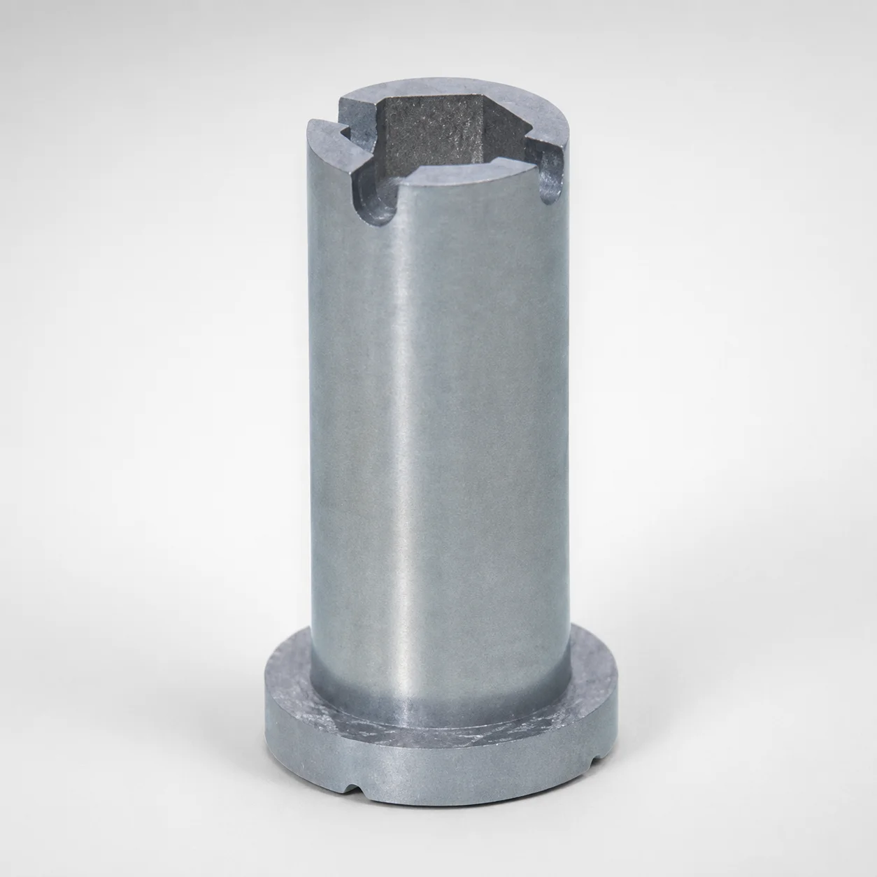
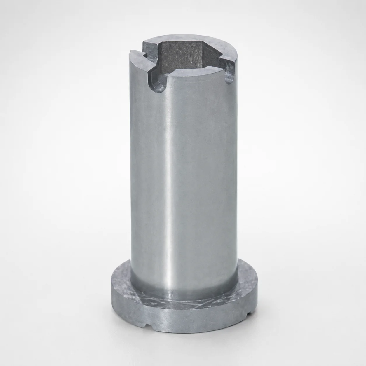
RCPK Fixed Side Runner Flow Direction Change Pins
Runner Flow Direction Change Pins for fixed side (RCPK) are designed to control runner flow direction with stable positioning in the mold assembly. This pin style supports consistent runner layout for dependable cycle-to-cycle results.
- RCPK fixed-side design improves runner flow direction repeatability during molding
- Compatible tip geometry options (N, I, T, K, L) to match different runner grooves
- Runner-groove aligned features support accurate contact and smooth flow switching
- Used in tooling where runner layout changes are required on fixed side components
Specifications
96 configurations available
| Tip Shape | D (Outer diameter) (mm) | A (Groove width, Runner groove, Shape A) (mm) | B (Semicircle, Runner groove, Shape B) (mm) | C (Virtual circle diameter, Runner groove, Shape C) (mm) | L (L dimension) (mm) | LC (L dimension alteration) (mm) | type |
|---|---|---|---|---|---|---|---|
| I | 8 | - | 1 ~ 1.5 | - | 15 ~ 50 | - | - |
| I | 8 | - | 1 ~ 1.5 | - | - | 15 ~ 49.9 | - |
| I | 8 | - | - | 2 | 15 ~ 50 | - | - |
| I | 8 | - | - | 2 | - | 15 ~ 49.9 | - |
| K | 8 | - | 1 ~ 1.5 | - | 15 ~ 50 | - | - |
| K | 8 | - | 1 ~ 1.5 | - | - | 15 ~ 49.9 | - |
| K | 8 | - | - | 2 | 15 ~ 50 | - | - |
| K | 8 | - | - | 2 | - | 15 ~ 49.9 | - |
| L | 8 | - | 1 ~ 1.5 | - | 15 ~ 50 | - | - |
| L | 8 | - | 1 ~ 1.5 | - | - | 15 ~ 49.9 | - |
| L | 8 | - | - | 2 | 15 ~ 50 | - | - |
| L | 8 | - | - | 2 | - | 15 ~ 49.9 | - |
| N | 8 | - | - | - | 15 ~ 50 | - | - |
| N | 8 | - | - | - | - | 15 ~ 49.9 | - |
| T | 8 | - | 1 ~ 1.5 | - | 15 ~ 50 | - | - |
| T | 8 | - | 1 ~ 1.5 | - | - | 15 ~ 49.9 | - |
| T | 8 | - | - | 2 | 15 ~ 50 | - | - |
| T | 8 | - | - | 2 | - | 15 ~ 49.9 | - |
| I | 10 | 3 | - | - | 15 ~ 50 | - | - |
| I | 10 | 3 | - | - | - | 15 ~ 49.9 | - |
| I | 10 | - | 1 ~ 2.5 | - | 15 ~ 50 | - | - |
| I | 10 | - | 1 ~ 2.5 | - | - | 15 ~ 49.9 | - |
| I | 10 | - | - | 2 ~ 2.5 | 15 ~ 50 | - | - |
| I | 10 | - | - | 2 ~ 2.5 | - | 15 ~ 49.9 | - |
| K | 10 | 3 | - | - | 15 ~ 50 | - | - |
| K | 10 | 3 | - | - | - | 15 ~ 49.9 | - |
| K | 10 | - | 1 ~ 2.5 | - | 15 ~ 50 | - | - |
| K | 10 | - | 1 ~ 2.5 | - | - | 15 ~ 49.9 | - |
| K | 10 | - | - | 2 ~ 2.5 | 15 ~ 50 | - | - |
| K | 10 | - | - | 2 ~ 2.5 | - | 15 ~ 49.9 | - |
| L | 10 | 3 | - | - | 15 ~ 50 | - | - |
| L | 10 | 3 | - | - | - | 15 ~ 49.9 | - |
| L | 10 | - | 1 ~ 2.5 | - | 15 ~ 50 | - | - |
| L | 10 | - | 1 ~ 2.5 | - | - | 15 ~ 49.9 | - |
| L | 10 | - | - | 2 ~ 2.5 | 15 ~ 50 | - | - |
| L | 10 | - | - | 2 ~ 2.5 | - | 15 ~ 49.9 | - |
| N | 10 | - | - | - | 15 ~ 50 | - | - |
| N | 10 | - | - | - | - | 15 ~ 49.9 | - |
| T | 10 | 3 | - | - | 15 ~ 50 | - | - |
| T | 10 | 3 | - | - | - | 15 ~ 49.9 | - |
| T | 10 | - | 1 ~ 2.5 | - | 15 ~ 50 | - | - |
| T | 10 | - | 1 ~ 2.5 | - | - | 15 ~ 49.9 | - |
| T | 10 | - | - | 2 ~ 2.5 | 15 ~ 50 | - | - |
| T | 10 | - | - | 2 ~ 2.5 | - | 15 ~ 49.9 | - |
| I | 13 | 3 ~ 4 | - | - | 15 ~ 60 | - | - |
| I | 13 | 3 ~ 4 | - | - | - | 15 ~ 59.9 | - |
| I | 13 | - | 1 ~ 3 | - | 15 ~ 60 | - | - |
| I | 13 | - | 1 ~ 3 | - | - | 15 ~ 59.9 | - |
| I | 13 | - | - | 2 ~ 3 | 15 ~ 60 | - | - |
| I | 13 | - | - | 2 ~ 3 | - | 15 ~ 59.9 | - |
Product Guide
Application Scenarios+
These runner flow direction change pins are used in injection mold runner systems where the flow must switch direction while remaining repeatable from shot to shot. They are commonly applied on the fixed side of a mold with an RCPK design, supporting stable positioning during assembly and maintaining consistent contact with the runner groove features.
- Automotive connector and housing molds: When runner layout changes are required to balance gate feeding across cavities, the pin’s fixed-side geometry helps maintain consistent flow switching and reduces variability across production cycles.
- Consumer electronics casings: For multi-cavity tools that demand controlled runner routing to minimize weld lines and fill-time differences, the compatible tip shapes (N, I, T, K, L) allow matching to specific runner groove profiles.
- General industrial parts with split runner routing: The aligned groove-interaction features promote smooth flow redirection and reliable seating in the tool.
Selection of the correct tip shape and diameter (D) ensures the pin mates correctly with the runner-groove interface for dependable switching.
Material & Process Details+
The provided product data specifies geometry and dimensional parameters (tip shape, D, groove dimensions, and lengths), but it does not list a steel grade or heat-treatment state. Because material properties such as wear resistance, toughness, and hardness depend on the actual manufacturing alloy for this component variant, those values cannot be stated from the current input.
When sourcing runner-change pins like this for high-cycle runner routing, engineers typically choose steels compatible with frequent sliding/contact at the runner-groove interface, then apply appropriate surface hardening (for example, nitriding or carburizing) and a quench-and-temper base heat treatment to balance wear resistance with toughness.
- Wear resistance vs. toughness trade-off: harder surface treatments improve groove-contact life, while maintaining sufficient core toughness helps resist chipping at repeated impact loads.
- Verification needed: confirm the specific steel grade and hardness from the supplier documentation for this exact part number.
Sizing & Selection Guide+
To select the correct runner flow direction change pin, match the tip geometry and key dimensions to the runner groove design on the fixed side (RCPK). Start by choosing the Tip Shape from the available set: I, K, L, N, T, because this determines how the pin engages the runner-groove contours.
- Outer diameter (D): Select D = 8, 10, 13, or 16 mm to fit the corresponding pin pocket/clearance in the mold.
- Runner groove geometry alignment: Verify the groove width/shape A ( 3, 3–4, or 3–6 mm ), semicircle/shape B ( 1–1.5, 1–2.5, 1–3, or 1–4 mm ), and virtual circle diameter/shape C ( 2, 2–2.5, 2–3, or 2–4 mm ).
- Axial length: Choose L = 15–50 mm (or 15–60 mm depending on LC option) and confirm LC is within 15–49.9 mm or 15–59.9 mm.
Maintain designer-verified clearance at the interface; even with correct D, small fit differences can affect seating and flow-switching repeatability.
Frequently Asked Questions
Which tip shape (N, I, T, K, L) should I select for my fixed-side runner groove?+
How do I match the pin outer diameter (D) to the mold’s pin pocket for RCPK fixed-side mounting?+
What groove dimensions (A, B, C) must be aligned to ensure reliable runner flow direction switching?+
How do I choose the correct L and LC values for the fixed-side assembly?+
Is this runner change pin intended only for fixed-side molds, or can it be used elsewhere?+
Related Products
Need Custom Specifications?
Our engineering team can help with custom configurations, material selection, and volume pricing.