Flow Rate Adjustment Pins
Adjustable pins and bolts for fine-tuning resin flow distribution across multiple cavities in injection molds.
Products — 2 Variants
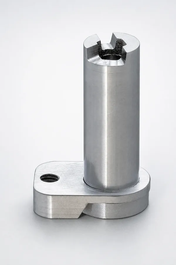
Adjustable Pins for Runner Flow Amount
Adjustable Pins for Runner Flow Amount with an adjustable pin type design to tune runner flow. Built for stable mold ...
View Details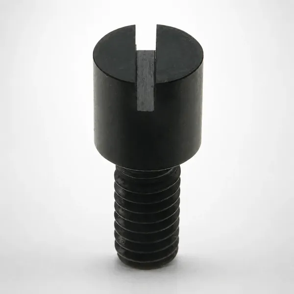
RRCB Adjustable Bolt Pins for Runner Flow Amount
RRCB Adjustable Bolt Pins for Runner Flow Amount for precise runner flow control in injection molds. Bolt pin type de...
View DetailsCompare Adjustment Methods
Two adjustment mechanisms serve different maintenance workflows:
| Feature | Adjustable Pin (RRCN) | Adjustable Bolt (RRCB) |
|---|---|---|
| Adjustment Method | Thread pin in/out with tool | Turn bolt head with wrench |
| Access | Requires tool access to pin end | Bolt head accessible from mold exterior |
| Adjustment Frequency | Set-and-forget applications | Frequent adjustments during production |
| Best For | Standard multi-cavity balancing | Family molds with frequent material/color changes |
Selection tip: For a detailed comparison, see our Adjustable Pins vs. Bolts guide.
How Flow Rate Adjustment Works
Principle
Flow rate adjustment pins install in runner channels where they partially obstruct the flow cross-section. By threading the pin in (more restriction) or out (less restriction), you control how much resin reaches each cavity.
When to Use
Multi-cavity molds with uneven filling are the primary use case. Uneven filling manifests as short shots in some cavities and flash in others. Instead of re-machining runner channels (expensive and irreversible), adjustable pins provide a tunable, reversible solution.
Installation
Pins install perpendicular to the runner flow direction. The pin tip protrudes into the runner channel, creating a variable restriction. The depth of protrusion determines the degree of flow restriction.
Balancing tip: Start with all pins at minimum restriction, then progressively restrict the fastest-filling cavities. See our Cavity Filling Balance Guide.
About Flow Rate Adjustment Pins
Flow rate adjustment pins and bolts are precision-threaded components that provide variable runner flow restriction. They install in cross-drilled holes in the runner plate and offer continuous adjustment range. Both types use hardened steel tips for wear resistance against flowing resin.
Application Scenarios
Flow adjustment is critical in these mold configurations:
Family Molds with Different Part Volumes
Molds producing different parts (e.g., lid + base) in the same shot. Different cavity volumes cause uneven filling.
Adjustable pins restrict flow to the smaller cavity, slowing its fill rate to match the larger cavity. Both parts fill simultaneously, preventing short shots and flash.
Naturally Unbalanced Runner Layouts
Molds where runner length varies between cavities due to layout constraints (not all cavities equidistant from sprue).
Pins add restriction to the shortest runner paths, equalizing flow arrival time at all cavities. Eliminates the need to redesign runner geometry.
Frequently Asked Questions
How do adjustable pins balance flow in multi-cavity molds?+
Adjustable pin vs adjustable bolt — which offers finer flow control?+
What runner diameter range do MISUMI flow rate adjustment pins fit?+
Engineering Resources
Need a Custom Quote?
Specify your runner diameter, adjustment type (pin/bolt), and number of cavities requiring flow control. Include runner cross-section dimensions for sizing confirmation.