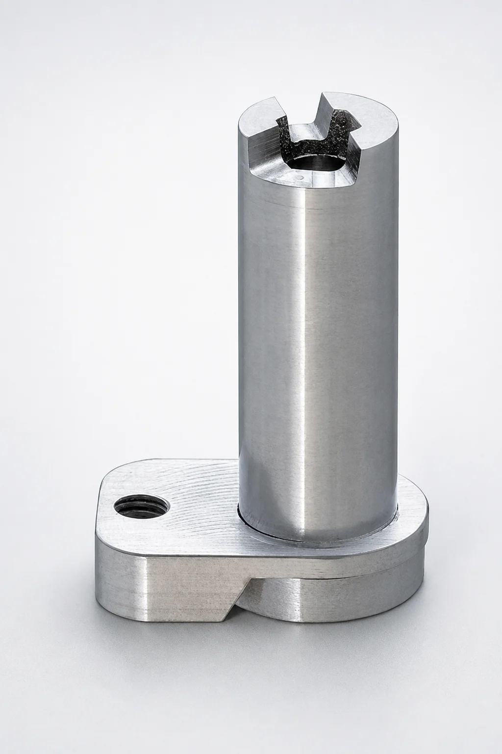
Adjustable Pins for Runner Flow Amount
Adjustable Pins for Runner Flow Amount provide a practical way to tune runner flow during mold assembly. The adjustable pin type supports consistent positioning for reliable part transfer and smoother production.
- Adjustable pin type for controlled changes in runner flow amount
- Runner-groove compatible top shapes (N, I, Y) to match design needs
- Supports multiple groove parameters for 8–16 mm runner flow adjustment pin dia.
- Used in runner groove configurations to help stabilize assembly fit and repeatability
Specifications
78 configurations available
| D (Runner Flow Rate Adjustment Pin Dia.) (mm) | Top Shape | Dimension designation type | A (Groove width, Runner groove, Shape A) (mm) | B (Semicircle, Runner groove, Shape B) (mm) | C (Virtual circle diameter, Runner groove, Shape C) (mm) | F (Ejector pin guide length) (mm) | L (L dimension) (mm) | LC (L dimension alteration) (mm) | P (Inner diameter) (mm) | type |
|---|---|---|---|---|---|---|---|---|---|---|
| 8 | I | L dimension designation | - | 1 ~ 1.5 | - | 8 ~ 30 | 15 ~ 50 | - | 3 | - |
| 8 | I | L dimension designation | - | - | 2 | 8 ~ 30 | 15 ~ 50 | - | 3 | - |
| 8 | N | L dimension designation | - | - | - | 8 ~ 30 | 15 ~ 50 | - | 3 | - |
| 8 | Y | L dimension designation | - | 1 ~ 1.5 | - | 8 ~ 30 | 15 ~ 50 | - | 3 | - |
| 8 | Y | L dimension designation | - | - | 2 | 8 ~ 30 | 15 ~ 50 | - | 3 | - |
| 10 | I | L dimension designation | 3 | - | - | 8 ~ 30 | 15 ~ 50 | - | 4 | - |
| 10 | I | L dimension designation | - | 1 ~ 2 | - | 8 ~ 30 | 15 ~ 50 | - | 4 | - |
| 10 | I | L dimension designation | - | - | 2 ~ 2.5 | 8 ~ 30 | 15 ~ 50 | - | 4 | - |
| 10 | N | L dimension designation | - | - | - | 8 ~ 30 | 15 ~ 50 | - | 4 | - |
| 10 | Y | L dimension designation | 3 | - | - | 8 ~ 30 | 15 ~ 50 | - | 4 | - |
| 10 | Y | L dimension designation | - | 1 ~ 2 | - | 8 ~ 30 | 15 ~ 50 | - | 4 | - |
| 10 | Y | L dimension designation | - | - | 2 ~ 2.5 | 8 ~ 30 | 15 ~ 50 | - | 4 | - |
| 13 | I | L dimension designation | 3 ~ 4 | - | - | 10 ~ 30 | 20 ~ 60 | - | 5 ~ 6 | - |
| 13 | I | L dimension designation | - | 1 ~ 3 | - | 10 ~ 30 | 20 ~ 60 | - | 5 ~ 6 | - |
| 13 | I | L dimension designation | - | - | 2 ~ 3 | 10 ~ 30 | 20 ~ 60 | - | 5 ~ 6 | - |
| 13 | N | L dimension designation | - | - | - | 10 ~ 30 | 20 ~ 60 | - | 5 ~ 6 | - |
| 13 | Y | L dimension designation | 3 ~ 4 | - | - | 10 ~ 30 | 20 ~ 60 | - | 5 ~ 6 | - |
| 13 | Y | L dimension designation | - | 1 ~ 2.5 | - | 10 ~ 30 | 20 ~ 60 | - | 5 ~ 6 | - |
| 13 | Y | L dimension designation | - | - | 2 ~ 3 | 10 ~ 30 | 20 ~ 60 | - | 5 ~ 6 | - |
| 16 | I | L dimension designation | 3 ~ 6 | - | - | 12 ~ 30 | 20 ~ 60 | - | 8 | - |
| 16 | I | L dimension designation | - | 1 ~ 4 | - | 12 ~ 30 | 20 ~ 60 | - | 8 | - |
| 16 | I | L dimension designation | - | - | 2 ~ 4 | 12 ~ 30 | 20 ~ 60 | - | 8 | - |
| 16 | N | L dimension designation | - | - | - | 12 ~ 30 | 20 ~ 60 | - | 8 | - |
| 16 | Y | L dimension designation | 3 ~ 4 | - | - | 12 ~ 30 | 20 ~ 60 | - | 8 | - |
| 16 | Y | L dimension designation | - | 1 ~ 2.5 | - | 12 ~ 30 | 20 ~ 60 | - | 8 | - |
| 16 | Y | L dimension designation | - | - | 2 ~ 3 | 12 ~ 30 | 20 ~ 60 | - | 8 | - |
| 8 | I | L dimension selection | - | 1 ~ 1.5 | - | - | 20 ~ 50 | - | 3 | - |
| 8 | I | L dimension selection | - | 1 ~ 1.5 | - | - | - | 20 ~ 49.9 | 3 | - |
| 8 | I | L dimension selection | - | - | 2 | - | 20 ~ 50 | - | 3 | - |
| 8 | I | L dimension selection | - | - | 2 | - | - | 20 ~ 49.9 | 3 | - |
| 8 | N | L dimension selection | - | - | - | - | 20 ~ 50 | - | 3 | - |
| 8 | N | L dimension selection | - | - | - | - | - | 20 ~ 49.9 | 3 | - |
| 8 | Y | L dimension selection | - | 1 ~ 1.5 | - | - | 20 ~ 50 | - | 3 | - |
| 8 | Y | L dimension selection | - | 1 ~ 1.5 | - | - | - | 20 ~ 49.9 | 3 | - |
| 8 | Y | L dimension selection | - | - | 2 | - | 20 ~ 50 | - | 3 | - |
| 8 | Y | L dimension selection | - | - | 2 | - | - | 20 ~ 49.9 | 3 | - |
| 10 | I | L dimension selection | 3 | - | - | - | 20 ~ 50 | - | 4 | - |
| 10 | I | L dimension selection | 3 | - | - | - | - | 20 ~ 49.9 | 4 | - |
| 10 | I | L dimension selection | - | 1 ~ 2 | - | - | 20 ~ 50 | - | 4 | - |
| 10 | I | L dimension selection | - | 1 ~ 2 | - | - | - | 20 ~ 49.9 | 4 | - |
| 10 | I | L dimension selection | - | - | 2 ~ 2.5 | - | 20 ~ 50 | - | 4 | - |
| 10 | I | L dimension selection | - | - | 2 ~ 2.5 | - | - | 20 ~ 49.9 | 4 | - |
| 10 | N | L dimension selection | - | - | - | - | 20 ~ 50 | - | 4 | - |
| 10 | N | L dimension selection | - | - | - | - | - | 20 ~ 49.9 | 4 | - |
| 10 | Y | L dimension selection | 3 | - | - | - | 20 ~ 50 | - | 4 | - |
| 10 | Y | L dimension selection | 3 | - | - | - | - | 20 ~ 49.9 | 4 | - |
| 10 | Y | L dimension selection | - | 1 ~ 2 | - | - | 20 ~ 50 | - | 4 | - |
| 10 | Y | L dimension selection | - | 1 ~ 2 | - | - | - | 20 ~ 49.9 | 4 | - |
| 10 | Y | L dimension selection | - | - | 2 ~ 2.5 | - | 20 ~ 50 | - | 4 | - |
| 10 | Y | L dimension selection | - | - | 2 ~ 2.5 | - | - | 20 ~ 49.9 | 4 | - |
Product Guide
Application Scenarios+
Where it’s used: Adjustable pins for runner flow tuning are installed in runner-groove tooling to fine-adjust the effective flow cross-section during mold setup. They are especially useful in sprue/bushing/gate assemblies where small changes can stabilize fill balance.
- Automotive connector molds: For multi-cavity parts that require consistent pack and fill, the adjustable pin type helps tune runner flow amount to reduce variability between cavities. The flow-rate adjustment pin diameters of 8–16 mm support matching common runner groove sizes, improving assembly fit repeatability.
- Consumer electronics housings: When gate location and runner resistance must be balanced for thin-wall features, the I/N/Y top-shape options allow alignment with runner-groove top geometries, supporting predictable flow behavior across production runs.
- Medical device component tooling: During early process development or parameter changes, using an adjustable pin design supports fast iteration without full rework of runner geometry, helping maintain stable mold assembly while responding quickly to flow deviations.
Why this variant fits: The pin design and groove-compatible top shapes (I, N, Y) are built to work with runner groove configurations, enabling controlled flow tuning while maintaining stable positioning.
Material & Process Details+
The provided product data specifies dimensional and geometric parameters for the adjustable runner flow tuning pin, but it does not list a specific steel grade, heat treatment state, or hardness (HRC). Because no material properties are included in the specifications, material selection and heat-treatment details must be confirmed via the product’s engineering documentation or quote sheet.
- Property intent: Runner flow adjustment components typically require dimensional stability under assembly loads, and adequate wear resistance to maintain the tuned runner geometry across repeated setups.
- Heat treatment note: If you source a hardened condition, the trade-off is usually higher wear resistance versus slightly reduced toughness if over-hardened; if pre-hardened, machining flexibility improves but wear resistance may be lower.
- Multiple materials: If alternatives are offered by MISUMI for the same dimensional designation, compare steel grade availability and reported HRC/hardness at the intended operating temperature range.
Action for selection: Request the material grade and heat treatment for series 110200084630 to ensure the hardness/toughness balance matches your runner groove wear expectations.
Sizing & Selection Guide+
Select the pin diameter D first based on the runner flow rate adjustment requirement: available D values are 8, 10, 13, and 16 mm. Choose the diameter that best matches your runner groove tuning target so the effective flow restriction/expansion created by the pin sits within the intended range.
- Match the top shape: Select Top Shape = I, N, or Y to align with your runner-groove top geometry. This compatibility helps ensure the adjustment pin seats correctly and preserves tuned repeatability during assembly.
- Verify groove compatibility parameters: Confirm your runner groove dimensions against the available ranges: A = 3 / 3–4 / 3–6 mm, B = 1–1.5 up to 1–4 mm, and C = 2–2.5 up to 2–4 mm. Use these ranges to select the designation that corresponds to your molded channel profile.
- Check length designations: Ejector pin guide length F = 8–30 (and variants 10–30, 12–30) mm, and L choices such as 15–50, 20–60, 20–50, 30–60 mm. Ensure LC selection fits within 20–49.9 or 20–59.9 mm as applicable.
Tolerance/fit consideration: Because this is used for stable mold assembly and repeat positioning, confirm the L/Lc designation and the inner diameter P (3, 4, 5–6, 8 mm) relative to the mating features to prevent seating variation during setup.
Frequently Asked Questions
Which runner groove top shape (I, N, Y) should I select for stable seating of an adjustable flow tuning pin?+
Choose the Top Shape to match the runner-groove top geometry used in your tooling. The product is described as runner-groove compatible for top shapes N, I, and Y, which helps the pin align correctly during mold assembly and supports repeatable tuned positioning.
How do I determine the correct adjustment pin diameter D for my runner flow balance changes?+
Select the Runner Flow Rate Adjustment Pin Dia. D from the available sizes: 8, 10, 13, or 16 mm. Then verify that the chosen designation aligns with your runner groove parameter ranges for A, B, and C so the tuned runner flow amount matches the intended flow cross-section.
What groove dimension ranges (A, B, C) are covered by this adjustable pin series?+
The specification provides discrete compatibility ranges for the runner groove parameters. For example, A includes 3, 3–4, and 3–6 mm; B spans multiple options such as 1–1.5 up to 1–4 mm; and C covers 2 through 2–4 mm depending on the designation.
How should I choose the L, LC, and F lengths to ensure proper guide engagement and repeatability?+
Use the designation ranges provided for this series: F = 8–30 (also 10–30 and 12–30 variants), and L selections such as 15–50, 20–60, 20–50, and 30–60 mm. Then confirm LC = 20–49.9 or 20–59.9 mm as applicable to your mating geometry.
Does this product specify a steel grade or hardness for wear resistance and toughness?+
The provided metadata for series 110200084630 includes runner groove and pin geometry, but it does not specify the steel grade, heat treatment state, or hardness (HRC). To select for wear resistance and toughness, request the material grade and heat treatment details from Axiom Molds/MISUMI for this exact designation.
Related Products
Need Custom Specifications?
Our engineering team can help with custom configurations, material selection, and volume pricing.