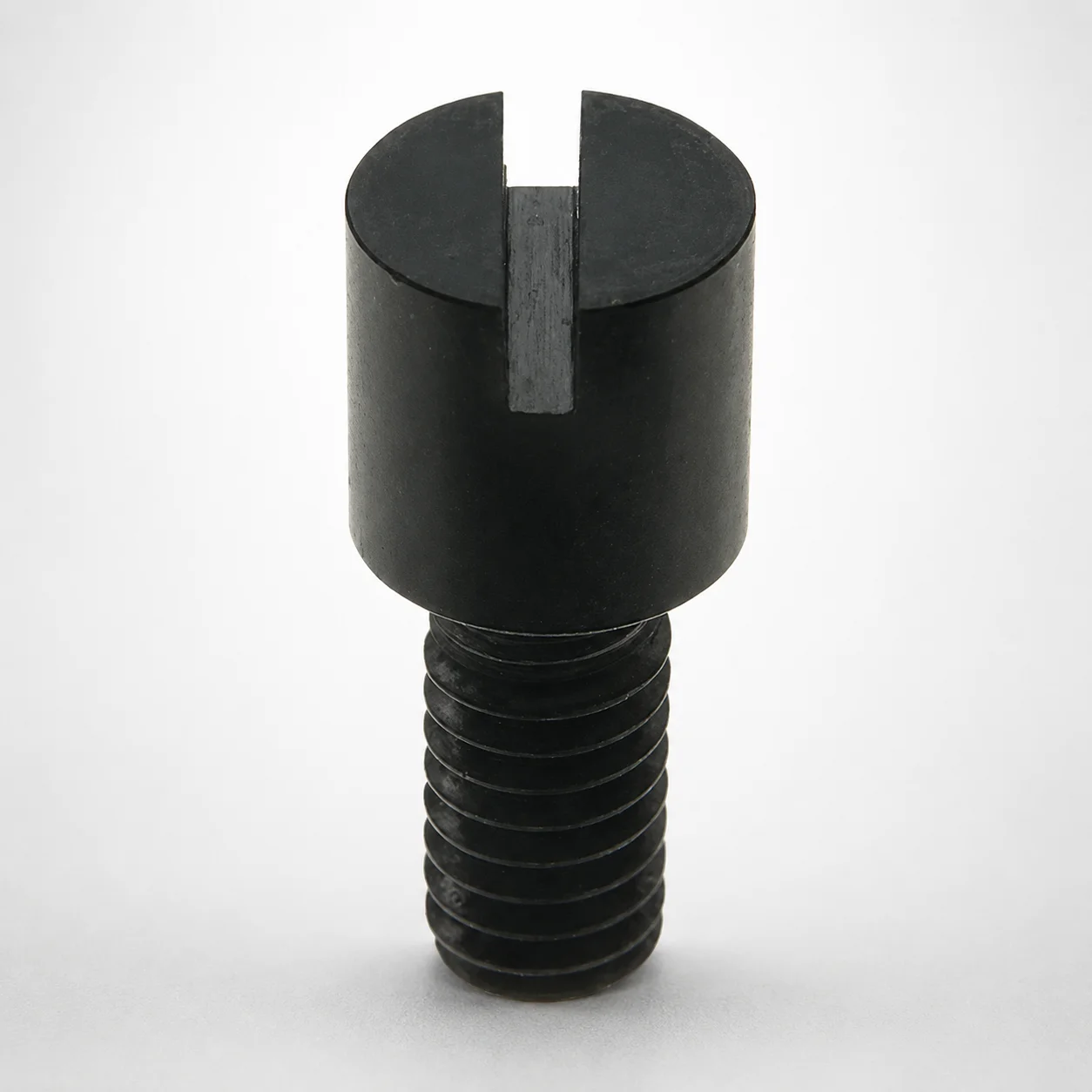
RRCB Adjustable Bolt Pins for Runner Flow Amount
RRCB adjustable bolt pins for runner flow amount are designed to fine-tune runner flow in injection molds using a bolt-style adjustment mechanism for reliable production control.
- Bolt pin type for controlled, repeatable runner flow amount adjustments
- Built with RRCB design to support stable positioning during operation
- Head geometry accommodates multiple configurations for fit with typical mold parts
- Used in injection molding systems requiring consistent flow balancing
Specifications
9 configurations available
| A (Head Diameter) (mm) | E (Head Thickness) (mm) | type |
|---|---|---|
| 6 | 4 | - |
| 6 | 6 | - |
| 6 | 8 | - |
| 8 | 6 | - |
| 8 | 8 | - |
| 8 | 10 | - |
| 10 | 8 | - |
| 10 | 10 | - |
| 10 | 12 | - |
Product Guide
Application Scenarios+
Where it’s used: These adjustable bolt pins are installed in runner/flow-control regions of injection molds to fine-tune how much melt enters specific runner branches.
How it’s used: Engineers set the runner flow amount by using the bolt-style adjustment to create repeatable runner flow conditions for stable cycle-to-cycle performance.
- Runner flow balancing in multi-cavity molds: Helps standardize fill between cavities by adjusting flow amount at the runner component interface.
- Automotive and appliance housings: Supports consistent filling of long or resistive flow paths where small flow variations can change part weight and knit-line location.
- Connector and insert-molding applications: Improves process robustness by maintaining predictable flow during switching between product families or material lots.
Why this variant suits these applications: The head diameter options (A = 6/8/10 mm) and head thickness options (E = 4/6/8/10/12 mm) enable secure, stable positioning and repeatable settings with typical runner-flow adjustment geometries.
Material & Process Details+
The provided dataset identifies this as an RRCB adjustable bolt pin for runner flow amount control, with key sizing defined by head diameter and thickness. However, it does not specify the steel grade, heat treatment state, or hardness values for this particular series code.
Implication for mold engineering: To ensure durability under repeated clamping/adjustment cycles, confirm the material specification from the manufacturer (and verify hardness/wear performance) for the intended shot pressure and temperature window.
- Heat treatment: Not listed in the current specifications—required to validate wear resistance at elevated mold temperatures.
- Hardness & toughness trade-offs: Cannot be stated from the supplied input; depends on the actual steel grade and whether it is quenched & tempered, pre-hardened, or surface-treated.
If multiple materials are available for the same geometry, choose based on required wear resistance versus shock/toughness, but the available comparison cannot be completed without the missing material/heat-treatment data.
Sizing & Selection Guide+
Correct selection depends on matching the pin head geometry to the runner-flow adjustment interface in your mold.
Available dimensions from the specification:
- Head diameter A: 6 mm, 8 mm, 10 mm
- Head thickness E: 4 mm, 6 mm, 8 mm, 10 mm, 12 mm
Selection method: Choose A to fit the mating recess/clearance envelope of the runner component without interference, and choose E to match the available bearing height so the pin can seat and maintain a stable adjusted position.
- Fit & tolerance: Use your mold’s machining allowances for the mating features; this dataset provides sizes but does not list tolerance bands, so confirm allowable clearance/dimensional control in your assembly drawings.
- Core/cavity compatibility: Verify that the selected head diameter and thickness do not conflict with adjacent parts that may move or experience thermal expansion.
These dimensions are configurable within the stated ranges; the series code remains the same for the product family.
Frequently Asked Questions
How do I choose the correct head diameter (A) for an RRCB runner flow adjustment bolt pin?+
Select A (6, 8, or 10 mm) based on the mating feature envelope in the runner-flow adjustment area. Use clearance allowances from your mold design drawings to prevent head interference during assembly and under thermal expansion.
Because the dataset does not provide tolerance values, validate the fit with your machining specification and the supplier’s dimensional control limits.
What head thickness (E) options are available, and how does E affect seating and repeatability?+
Head thickness E is available as 4, 6, 8, 10, or 12 mm. Choose E to match the available bearing height so the pin seats properly and maintains a stable, repeatable adjusted position.
If E is too small, seating height may vary; if too large, it can cause interference with adjacent runner components.
Is there a standard material/heat treatment specified for series 110200185070 RRCB adjustable bolt pins?+
The provided product data specifies only geometric dimensions (A and E) and does not include the steel grade, hardness (HRC), or heat treatment state. To finalize material selection for your required wear resistance and toughness, request the material/heat-treatment documentation for the exact series code.
Confirm suitability for your mold temperature and runner-flow adjustment load conditions.
Which runner-flow control applications benefit most from bolt-style repeatable settings?+
Bolt-style adjustment is typically used in molds where consistent runner fill is required across cycles or cavities. This includes multi-cavity runner flow balancing and long/resistive flow paths where small flow differences impact part weight, fill balance, or knit-line appearance.
Use the available head geometry options (A = 6/8/10 mm, E = 4/6/8/10/12 mm) to match your runner component interface.
Do I need different pins for different mold cavities, or can one sizing option cover multiple assemblies?+
Use the pin only when its A and E match the specific mating geometry in that mold assembly. Even for the same series code, changing the runner component interface typically requires selecting the appropriate head diameter and thickness from the listed options.
Because tolerance ranges are not provided in the dataset, verify that your assembly clearance and seating requirements are met for each cavity layout.
Related Products
Need Custom Specifications?
Our engineering team can help with custom configurations, material selection, and volume pricing.