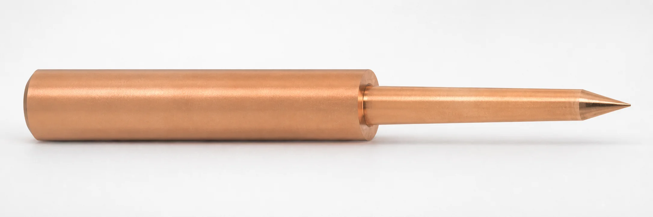
EMPGA Pin-Point Gate Processing Electrodes (Oxygen-Free Copper)
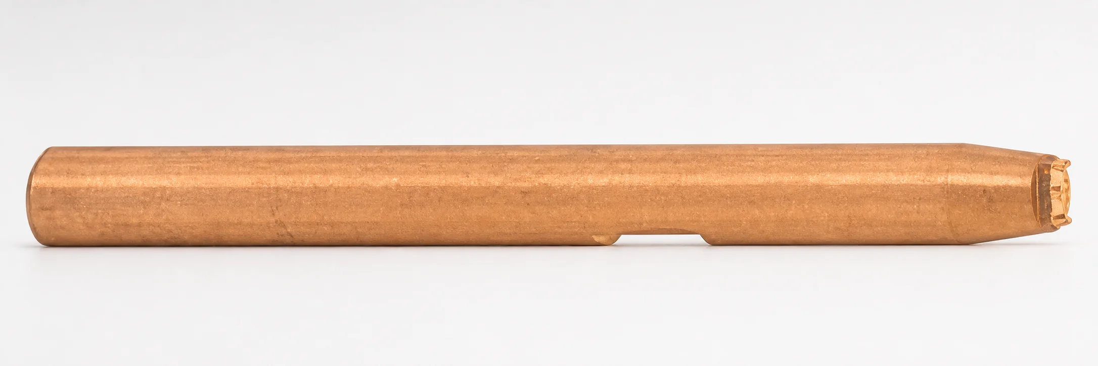
EMPGA pin-point gate processing electrodes (oxygen-free copper) are engineered for consistent gate processing performance. They support stable machining and finishing results during production workflows that require precise gate work.
- Built for pin-point gate processing and gate finishing operations
- Uses oxygen-free copper for stable conductivity and controlled wear
- Supports multiple nominal diameters and L dimension options for fitting needs
- Compatible with EMPGA type electrode systems used in gate processing
Specifications
9 configurations available
| No. (Nominal diameter) (mm) | L (L dimension) (mm) | G (Taper angle) (°) | type |
|---|---|---|---|
| 0.8 | 50 ~ 70 | 20 ~ 60 | - |
| 1 | 50 ~ 70 | 20 ~ 60 | - |
| 1.2 | 50 ~ 90 | 20 ~ 60 | - |
| 1.5 | 50 ~ 90 | 20 ~ 60 | - |
| 2 | 50 ~ 110 | 20 ~ 60 | - |
| 2.5 | 50 ~ 110 | 20 ~ 60 | - |
| 3 | 50 ~ 110 | 20 ~ 60 | - |
| 3.5 | 50 ~ 90 | 20 ~ 60 | - |
| 4 | 50 ~ 90 | 20 ~ 60 | - |
Product Guide
Application Scenarios+
These oxygen-free copper point electrodes are used in injection mold tooling wherever pin-point gate processing and gate finishing are required, particularly after casting or during gate rework workflows. In die casting gates, they help maintain consistent electrical/processing stability so the gate geometry can be finished to a controlled profile.
- Pin-point gate finishing for die casting: Suitable when tight gate definition and repeatable finishing are needed; the oxygen-free copper variant supports stable conductivity for reliable machining/processing results.
- Gate processing in EMPGA-type electrode systems: Designed for compatibility with EMPGA electrode setups used by mold shops to standardize gate treatment sequences and reduce variation between runs.
- Multi-diameter mold gate applications: Available nominal diameters from 0.8 to 4 mm and selectable L lengths to match different gate sizes and recessed electrode standoff requirements.
With a specified taper angle range of 20–60°, the electrode can be matched to the required gate taper for consistent finishing performance.
Material & Process Details+
This electrode is made from oxygen-free copper, selected for stable electrical conductivity and predictable machining/processing behavior. In gate processing contexts, this helps promote controlled wear characteristics, supporting repeatable electrode performance across production cycles.
- Conductivity & wear behavior: Oxygen-free copper supports steady current transmission and helps maintain consistent processing outcomes during gate finishing.
- Hardness/toughness trade-off: Copper offers good stability for processing tasks, but it is generally softer than tool steels; therefore, it’s best treated as an electrode/processing component rather than a high-wear mechanical tool insert.
- Heat treatment: No specific quench-and-temper, nitriding, or target HRC value is provided for this item; validation should be done against the supplier’s manufacturing documentation for any special finishing or conditioning steps.
Compared with steel electrodes, oxygen-free copper emphasizes conductivity and controlled processing behavior over maximum wear resistance.
Sizing & Selection Guide+
Select the nominal diameter and L length to match the mold’s gate feature size and the electrode reach required by your gate processing setup. The available nominal diameter range is 0.8–4 mm, covering small to medium pin-point gate geometries.
- Nominal diameter (No.): Choose a diameter that fits the gate region targeted for finishing without forcing misalignment. Use the closest working diameter within 0.8–4 mm to maintain consistent gate profile results.
- L dimension: Select one of the provided 50–70 mm, 50–90 mm, or 50–110 mm options to achieve the required reach/standoff for the mold cavity/core layout.
- Taper angle (G): The taper angle is fixed within 20–60° selection; align the taper to the expected gate taper for controlled finishing.
Because tolerance values are not specified, confirm fit through your electrode holder and EMPGA-type system alignment requirements. If exact cavity depth varies, prefer the L range that provides full reach while minimizing unnecessary overtravel.
Frequently Asked Questions
Which nominal diameter (0.8–4 mm) should I choose for pin-point gate finishing?+
Use the nominal diameter (No.) range of 0.8–4 mm to match the gate feature size you intend to finish. Selecting the closest workable diameter helps maintain the intended gate geometry without excessive clearance.
After selection, verify alignment in the EMPGA electrode system to reduce variations from run to run.
How do I select the correct L dimension (50–70 / 50–90 / 50–110 mm) for my mold geometry?+
Pick the L option that provides adequate reach from your electrode holder position to the target gate region. Use 50–70 mm, 50–90 mm, or 50–110 mm based on cavity depth and required standoff.
Because tolerances are not provided, confirm holder/electrode alignment with your EMPGA-type tooling before production.
What is the impact of the taper angle range (G = 20–60°) on gate processing results?+
The taper angle is specified as G = 20–60° for this electrode family. Matching the electrode taper to the gate taper you are finishing supports more controlled gate profile reproduction.
If your mold gate has a specific taper requirement, ensure the selected electrode taper aligns with the processing objective.
Is this oxygen-free copper electrode compatible with EMPGA-type electrode systems?+
Yes. The provided description states compatibility with EMPGA type electrode systems used in gate processing workflows.
When integrating, confirm that your electrode holder and electrical/processing parameters are set for the selected copper electrode dimensions (No. and L).
Why choose oxygen-free copper for gate processing electrodes instead of tool steels?+
This item uses oxygen-free copper, emphasizing stable conductivity for reliable gate processing and finishing. In applications like die casting gate finishing, stable electrical behavior helps support consistent processing outcomes.
Unlike hardened tool steels, copper is not specified with HRC or heat treatment in the given data, so it’s typically selected for its processing characteristics rather than maximum mechanical wear resistance.
Related Products
Need Custom Specifications?
Our engineering team can help with custom configurations, material selection, and volume pricing.