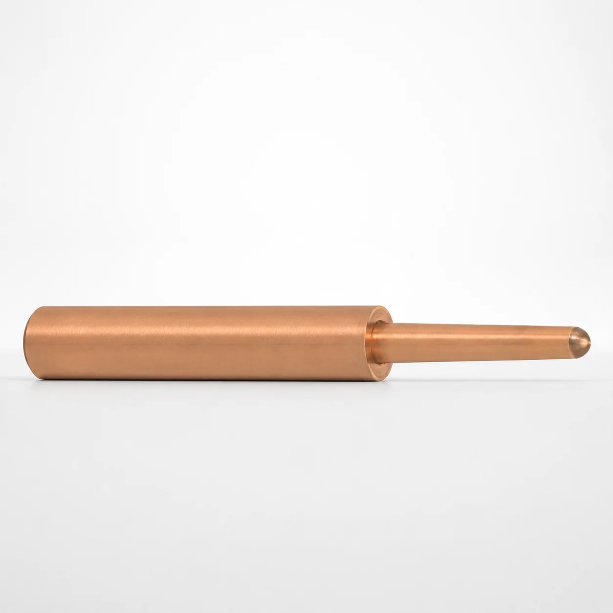
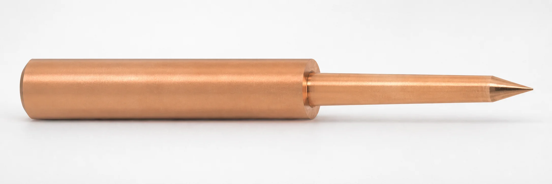
EMPG Type Oxygen-Free Copper Electrodes for Pin-Point Gate - for SR Processing
Electrodes for Pin-Point Gate - for SR Processing (EMPG type) are made from oxygen-free copper to support stable electrical discharge conditions. Designed specifically for SR processing to help maintain consistent gate formation.
- EMPG type electrodes matched to SR processing requirements
- Oxygen-free copper construction for reliable electrical conductivity
- Compatible with pin-point gate workflows using configurable No., L, and A settings
- Typical use in EDM/spark discharge setups for pin-point gate formation
Specifications
9 configurations available
| No. (Nominal diameter) (mm) | L (L dimension) (mm) | A (Taper angle) (°) | type |
|---|---|---|---|
| 0.8 | 50 ~ 70 | 1 ~ 3 | - |
| 1 | 50 ~ 70 | 1 ~ 3 | - |
| 1.2 | 50 ~ 90 | 1 ~ 3 | - |
| 1.5 | 50 ~ 90 | 1 ~ 3 | - |
| 2 | 50 ~ 110 | 1 ~ 3 | - |
| 2.5 | 50 ~ 110 | 1 ~ 3 | - |
| 3 | 50 ~ 110 | 1 ~ 3 | - |
| 3.5 | 50 ~ 110 | 1 ~ 3 | - |
| 4 | 50 ~ 110 | 1 ~ 3 | - |
Product Guide
Application Scenarios+
These EMPG-type electrodes are used in pin-point gate mold tooling where stable EDM/spark discharge is required to form precise gate features. In SR processing workflows, the oxygen-free copper construction supports steady electrical discharge conditions, which helps maintain consistent gate geometry from cavity to cavity.
Common scenarios include automotive connector and housing molds, where pinpoint gates reduce weld lines and improve cosmetic consistency. They are also used for small precision components (e.g., medical and electronic housings) that need tight control over gate location and size to avoid gate vestige variation.
- EDM/spark discharge setups: select the electrode dimensions to match the pinpoint gate pocket and ensure consistent burn control.
- SR processing: the EMPG variant and taper angle range (1–3°) are suited for maintaining repeatable discharge behavior during gate formation.
Material & Process Details+
This electrode uses oxygen-free copper (OFC), selected for its high electrical conductivity and stable discharge performance during EDM/spark discharge. Compared with copper alloys, OFC is typically preferred when uniform conductivity and predictable electrical behavior are critical for pinpoint gate formation.
- Hardness / wear balance: copper-based electrodes generally trade lower hardness for excellent current-carrying capability; this prioritizes stable discharge over extreme wear resistance.
- Heat treatment: the provided data does not specify a quench-and-temper or nitriding treatment state, so the selection should be based on the supplied OFC material condition from the manufacturer.
- EDM behavior: stable conductivity helps reduce discharge fluctuations that can otherwise affect gate contour consistency.
For applications requiring maximum abrasion resistance, engineers may consider alternative electrode materials, but for SR processing pinpoint gates, OFC’s electrical stability is the key property.
Sizing & Selection Guide+
Correct electrode sizing is critical for matching the pin-point gate feature geometry in the mold. Use the three parameters provided: No. (nominal diameter, 0.8–4 mm), L (length, 50–70, 50–90, or 50–110 mm options), and A (taper angle, fixed range 1–3°).
- Match No. to gate diameter: select the nominal diameter (0.8–4 mm) to align with the pinpoint gate’s target throat/diameter requirements.
- Match L to electrode reach: choose the L range (50–70, 50–90, or 50–110 mm) based on cavity depth and how much electrode length is needed to reach the discharge zone.
- Set taper angle A: select within 1–3° to control the formed gate profile and taper behavior.
Concerning tolerances: the input data provides dimension ranges but no explicit tolerance values, so confirm fit and clearance against your holder/tooling drawings. If your SR process uses configurable settings, keep No./L/A consistent between electrode batches to maintain repeatable gate formation.
Frequently Asked Questions
Which EMPG electrode dimensions should I choose for a pinpoint gate SR processing job?+
Select No. (0.8–4 mm) to match the pinpoint gate target diameter, then choose L based on required electrode reach (50–70, 50–90, or 50–110 mm). Keep A within the specified taper angle range of 1–3° to control the gate profile during discharge.
Why is oxygen-free copper specified for stable electrical discharge in pinpoint gate formation?+
The electrode is made from oxygen-free copper to support stable electrical discharge behavior during EDM/spark discharge. Higher electrical conductivity helps reduce discharge fluctuation effects that can impact repeatability of the gate contour.
What does the fixed taper angle range (1–3°) mean for the resulting gate shape?+
The product specifies A as a taper angle within 1–3°. In EDM-based pinpoint gate work, adjusting taper can influence the formed gate’s profile, helping engineers better match the desired gate geometry for SR processing.
How do I ensure the electrode length L will reach the discharge zone in deep cavities?+
Use the available L ranges (50–70, 50–90, or 50–110 mm) to cover cavity depth and setup requirements. If the discharge zone is deeper, select the larger L option to maintain reach without compromising alignment.
Is this electrode compatible with standard pin-point gate EDM setups?+
It is intended for pin-point gate workflows using EDM/spark discharge setups, specifically for SR processing conditions. Ensure your machine/tooling can accept the selected No., L, and A ranges before running production gate forming.
Related Products
Need Custom Specifications?
Our engineering team can help with custom configurations, material selection, and volume pricing.