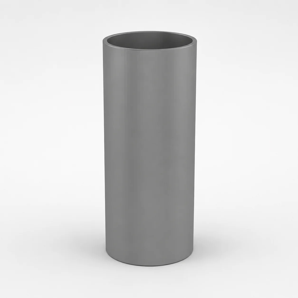
Spring Cages - Inch & Metric
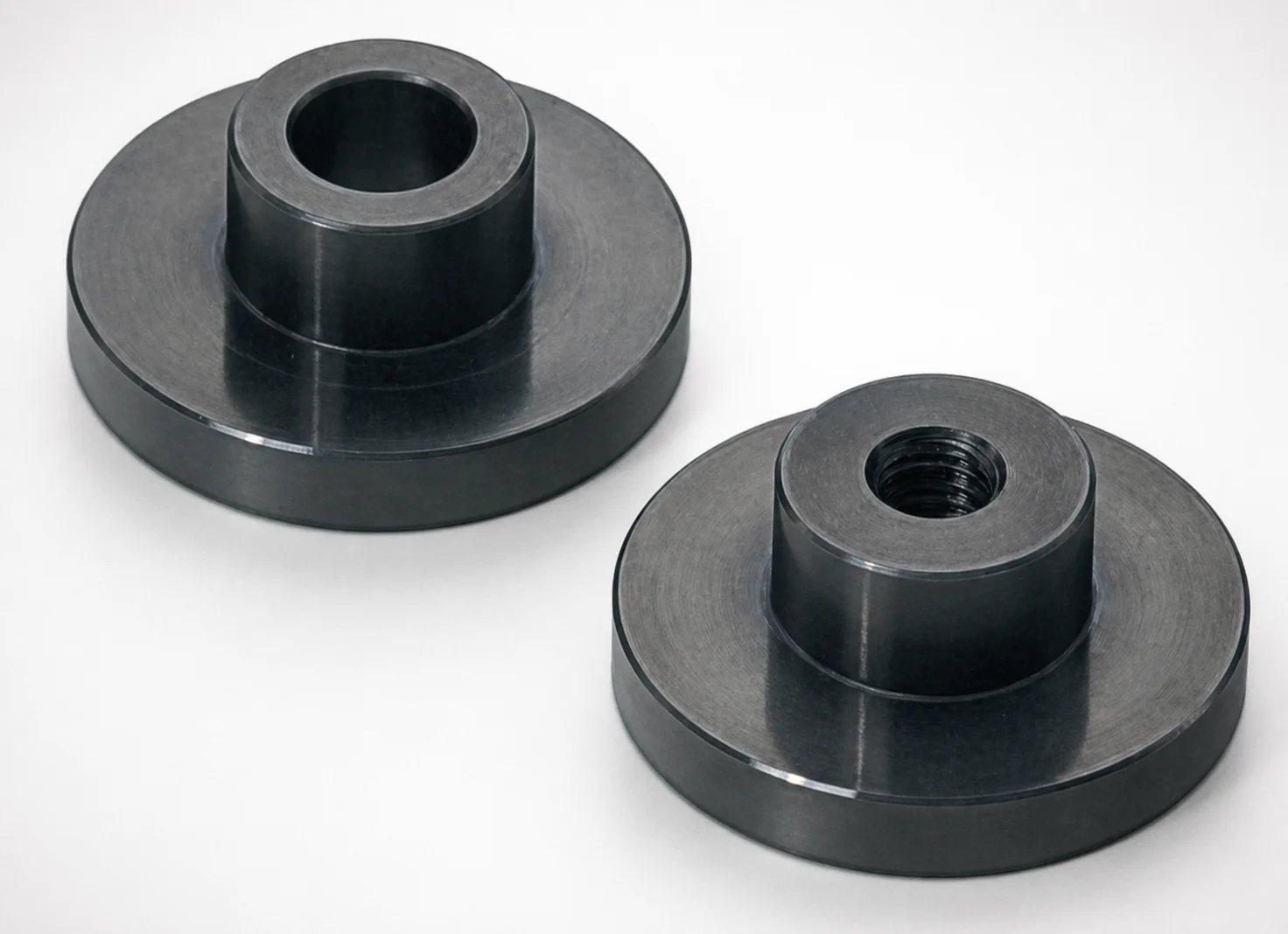
Spring Cages - Inch & Metric (DANLY IEM) are steel guide supports built to stabilize coil spring components across both inch and metric setups. They help prevent misalignment and reduce wear for more consistent operation in demanding production.
- Steel construction for reliable spring-unit support and alignment stability
- Designed for both inch and metric dimensional systems for easier integration
- Helps minimize component wear to support stable motion and lower maintenance
- Suitable for tool environments where reliable positioning improves uptime
Specifications
118 configurations available
| Spring Diameter (mm) | L (Guide length) (mm) | Spring Diameter (in) | L (Guide length) (in) |
|---|---|---|---|
| 20 | 25 | 3/4" | 1" |
| 20 | 32 | 3/4" | 1-1/4" |
| 20 | 38 | 3/4" | 1-1/2" |
| 20 | 44 | 3/4" | 1-3/4" |
| 20 | 51 | 3/4" | 2" |
| 20 | 57 | 3/4" | 2-1/4" |
| 20 | 64 | 3/4" | 2-1/2" |
| 20 | 70 | 3/4" | 2-3/4" |
| 20 | 76 | 3/4" | 3" |
| 20 | 83 | 3/4" | 3-1/4" |
| 20 | 89 | 3/4" | 3-1/2" |
| 20 | 95 | 3/4" | 3-3/4" |
| 20 | 102 | 3/4" | 4" |
| 20 | 108 | 3/4" | 4-1/4" |
| 20 | 114 | 3/4" | 4-1/2" |
| 20 | 121 | 3/4" | 4-3/4" |
| 20 | 127 | 3/4" | 5" |
| 20 | 140 | 3/4" | 5-1/2" |
| 20 | 152 | 3/4" | 6" |
| 20 | 165 | 3/4" | 6-1/2" |
| 20 | 178 | 3/4" | 7" |
| 20 | 203 | 3/4" | 8" |
| 25 | 25 | 1" | 1" |
| 25 | 32 | 1" | 1-1/4" |
| 25 | 38 | 1" | 1-1/2" |
| 25 | 44 | 1" | 1-3/4" |
| 25 | 51 | 1" | 2" |
| 25 | 57 | 1" | 2-1/4" |
| 25 | 64 | 1" | 2-1/2" |
| 25 | 70 | 1" | 2-3/4" |
| 25 | 76 | 1" | 3" |
| 25 | 83 | 1" | 3-1/4" |
| 25 | 89 | 1" | 3-1/2" |
| 25 | 95 | 1" | 3-3/4" |
| 25 | 102 | 1" | 4" |
| 25 | 108 | 1" | 4-1/4" |
| 25 | 114 | 1" | 4-1/2" |
| 25 | 121 | 1" | 4-3/4" |
| 25 | 127 | 1" | 5" |
| 25 | 140 | 1" | 5-1/2" |
| 25 | 152 | 1" | 6" |
| 25 | 165 | 1" | 6-1/2" |
| 25 | 178 | 1" | 7" |
| 25 | 203 | 1" | 8" |
| 32 | 25 | 1-1/4" | 1" |
| 32 | 32 | 1-1/4" | 1-1/4" |
| 32 | 38 | 1-1/4" | 1-1/2" |
| 32 | 44 | 1-1/4" | 1-3/4" |
| 32 | 51 | 1-1/4" | 2" |
| 32 | 57 | 1-1/4" | 2-1/4" |
Product Guide
Application Scenarios+
Spring cages are used inside injection mold tooling to provide a stable guide environment for coil-spring-driven systems, where consistent linear motion directly affects part quality and cycle reliability.
- Automotive and appliance actuation mechanisms: Pair the cage with spring guides to keep moving components aligned under repeated opening/closing loads, reducing off-axis wear that can lead to sticking or uneven travel.
- Electronics and connector housings: In molds that require tight repeatability of spring return, the cage’s steel support helps maintain guide geometry, supporting stable operation across high-volume production.
- Packaging and consumer goods tooling: For fast-cycle tools, a robust guide support limits misalignment-driven friction, which helps extend maintenance intervals.
This Inch & Metric variant is suited because it is offered for multiple spring diameters (20–50 mm and 3/4–2 in) and guide lengths (L = 25–305 mm / 1–12 in), enabling designers to match the cage to both standardized inch and metric spring guide layouts.
Material & Process Details+
This component is specified as a steel guide support intended to stabilize coil spring guidance and reduce wear caused by misalignment. While no specific alloy grade, hardness (HRC), or heat-treatment state is provided in the data, the steel construction supports durability in tooling environments where repeated spring loading and sliding contact occur.
- Wear resistance vs. toughness trade-off: In general steel guide supports prioritize dimensional stability and surface durability; selecting an appropriate hardened condition improves wear resistance but can reduce impact toughness if over-hardened.
- Manufacturing process: Typical production involves precision fabrication followed by finishing operations to achieve alignment-critical guide features and consistent assembly fit.
If your application demands a defined hardness level or specific heat treatment (e.g., nitriding or quench & temper), request the exact material/heat-treatment specification for series 250300462349 to confirm performance targets.
Sizing & Selection Guide+
Correct selection is driven by matching both the spring diameter and the guide length (L) to your mold’s spring-guided mechanism envelope.
- Spring diameter (mm): choose 20, 25, 32, 40, or 50 mm.
- Spring diameter (in): choose 3/4", 1", 1-1/4", 1-1/2", or 2".
- Guide length L (mm): select from 25 ~ 305 mm.
- Guide length L (in): select from 1 ~ 12 in.
When designing the cavity/core or moving assembly, confirm the cage’s L dimension matches the available guided travel region, including any clearance needed for spring compression and assembly tolerances. Use the appropriate inch or metric sizing system to avoid unit mismatch, and verify that the chosen spring diameter aligns with the mating spring guide/support bore geometry to maintain concentric motion and minimize wear.
Frequently Asked Questions
Which spring diameters are compatible with the Spring Cages (Inch & Metric) for series 250300462349?+
Compatible spring diameters are specified as 20, 25, 32, 40, 50 mm and 3/4", 1", 1-1/4", 1-1/2", 2". Select the cage size using the same unit system (inch or metric) as your spring and guide design to prevent dimensional mismatch.
How do I select the correct guide length L for the mold assembly?+
The guide length L is available in 25 ~ 305 mm or 1 ~ 12 in ranges, depending on the inch/metric configuration. Match L to the available guided region in the mold such that spring compression and movement occur within the supported length without binding.
Is this cage intended for both inch and metric spring guide layouts in the same tooling program?+
Yes. This variant is explicitly offered for both inch and metric dimensional systems, with spring diameters and guide lengths listed in both units. Use the corresponding inch or metric size to keep mating features consistent across your tool design.
What performance factors should I verify if I need reduced wear from spring misalignment?+
The cage is designed as a steel guide support to stabilize coil spring operation and prevent misalignment-driven wear. To meet wear targets, ensure the selected spring diameter (20–50 mm or 3/4–2 in) and L (25–305 mm or 1–12 in) align with the mechanism envelope so the guided motion stays concentric.
Do you provide the steel grade, hardness (HRC), or heat-treatment details for this spring cage series?+
The provided specification data confirms steel construction but does not list a specific steel grade, hardness (HRC), or heat-treatment condition. If your design requires a defined wear-resistant condition, request the exact material/heat-treatment specification for series 250300462349.
Related Products
Need Custom Specifications?
Our engineering team can help with custom configurations, material selection, and volume pricing.