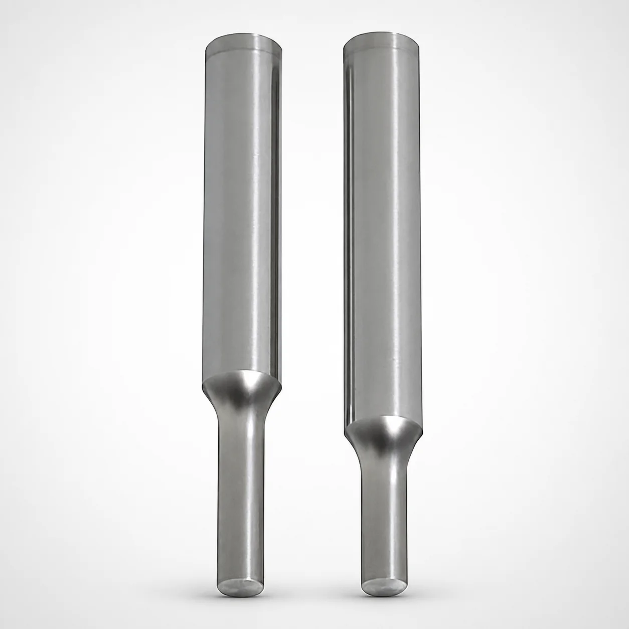
RP Coating Tapped Punches
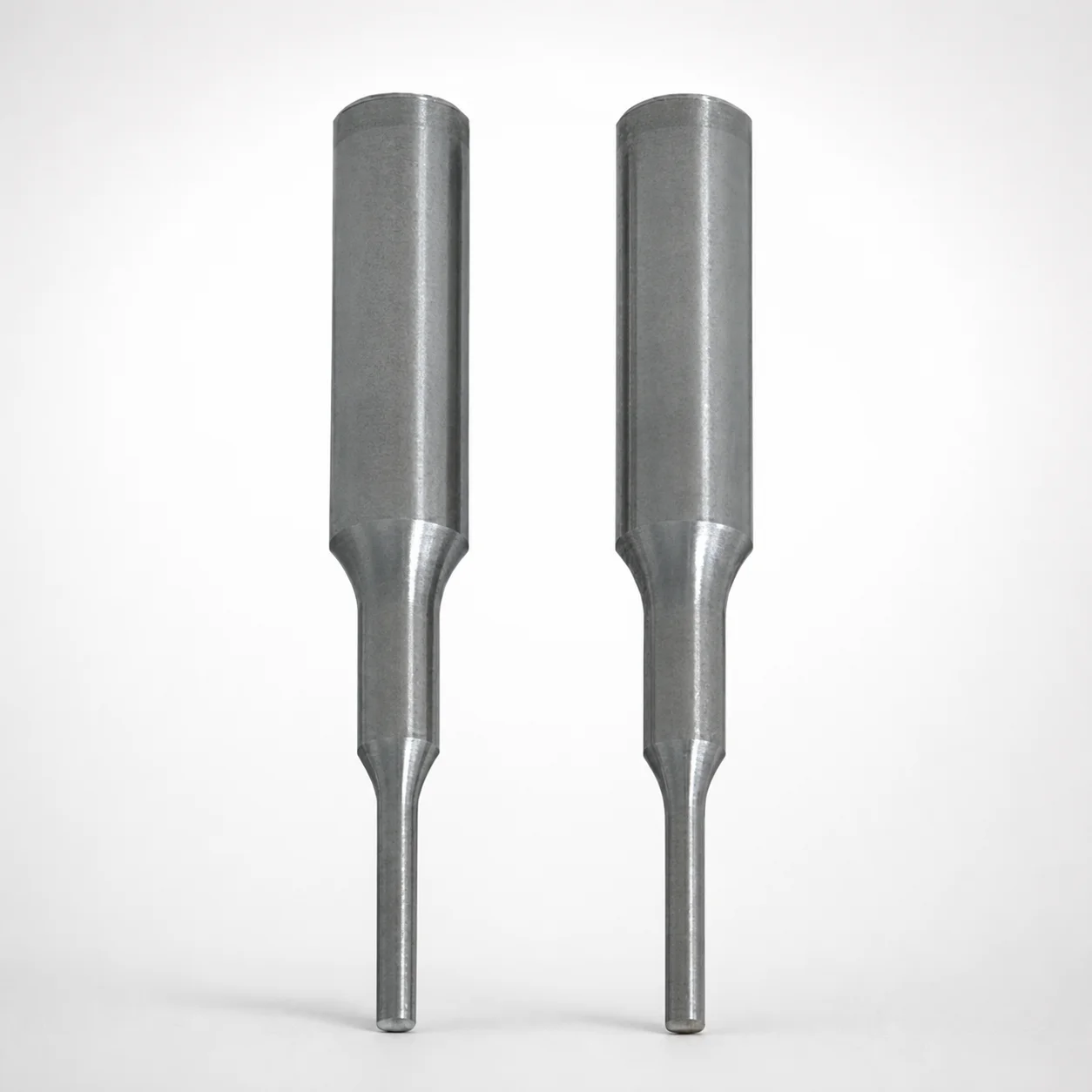
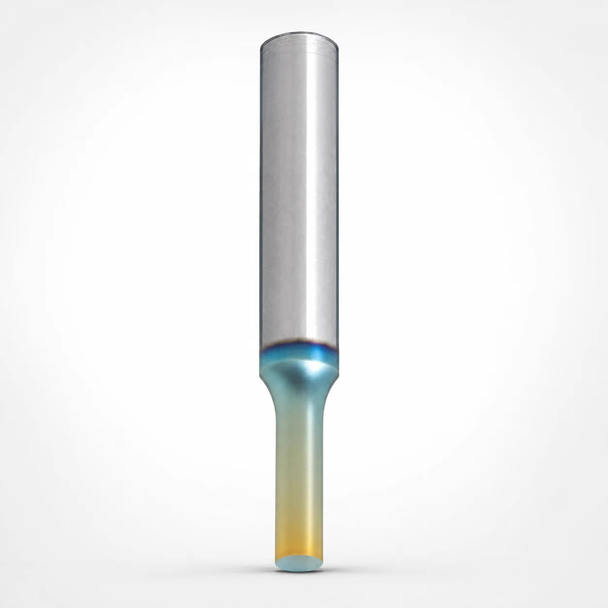
RP coating tapped punches feature an Al-Cr based coating for high hardness and heat resistance, while alpha treatment strengthens substrate performance to improve coating adhesion and overall tool durability.
- Al-Cr based RP coating designed for high hardness and heat resistance in punching cycles
- Alpha treatment enhances wear resistance and improves adhesion of the coating film
- Supports longer punch life even where traditional coatings struggled, helping lower maintenance effort
- Ideal for mold shops using standard tapping punch formats and repeat production runs
Specifications
1648 configurations available
| Tip shape | Shank diameter D tolerance | B (Tip length) | D (Shank diameter) (mm) | P (Tip dimension) (mm) | L (L dimension) (mm) | Specification | LC (Full length alteration) (mm) | R (Tip corner R) (mm) | PC (Tip dimension alteration) (mm) | W (Tip dimension) (mm) | WC (Tip dimension alteration) (mm) | type |
|---|---|---|---|---|---|---|---|---|---|---|---|---|
| A | +0.005/0 | L | 5 | 2 ~ 4.99 | 50 ~ 80 | Tap standard type | - | - | - | - | - | - |
| A | +0.005/0 | L | 5 | - | 50 ~ 80 | Tap standard type | - | - | 1 ~ 1.99 | - | - | - |
| A | +0.005/0 | L | 5 | 2 ~ 4.99 | - | Tap standard type | 27 ~ 79.9 | - | - | - | - | - |
| A | +0.005/0 | L | 5 | - | - | Tap standard type | 27 ~ 79.9 | - | 1 ~ 1.99 | - | - | - |
| A | +0.005/0 | L | 6 | 2 ~ 5.99 | 50 ~ 80 | Tap standard type | - | - | - | - | - | - |
| A | +0.005/0 | L | 6 | - | 50 ~ 80 | Tap standard type | - | - | 1 ~ 1.99 | - | - | - |
| A | +0.005/0 | L | 6 | 2 ~ 5.99 | - | Tap standard type | 27 ~ 79.9 | - | - | - | - | - |
| A | +0.005/0 | L | 6 | - | - | Tap standard type | 27 ~ 79.9 | - | 1 ~ 1.99 | - | - | - |
| A | +0.005/0 | L | 8 | 3 ~ 7.99 | 50 ~ 100 | Tap standard type | - | - | - | - | - | - |
| A | +0.005/0 | L | 8 | - | 50 ~ 100 | Tap standard type | - | - | 1.5 ~ 2.99 | - | - | - |
| A | +0.005/0 | L | 8 | 3 ~ 7.99 | - | Tap standard type | 27 ~ 99.9 | - | - | - | - | - |
| A | +0.005/0 | L | 8 | - | - | Tap standard type | 27 ~ 99.9 | - | 1.5 ~ 2.99 | - | - | - |
| A | +0.005/0 | L | 10 | 3 ~ 9.99 | 50 ~ 100 | Tap standard type | - | - | - | - | - | - |
| A | +0.005/0 | L | 10 | - | 50 ~ 100 | Tap standard type | - | - | 1.5 ~ 2.99 | - | - | - |
| A | +0.005/0 | L | 10 | 3 ~ 9.99 | - | Tap standard type | 27 ~ 99.9 | - | - | - | - | - |
| A | +0.005/0 | L | 10 | - | - | Tap standard type | 27 ~ 99.9 | - | 1.5 ~ 2.99 | - | - | - |
| A | +0.005/0 | L | 13 | 6 ~ 12.99 | 50 ~ 100 | Tap standard type | - | - | - | - | - | - |
| A | +0.005/0 | L | 13 | - | 50 ~ 100 | Tap standard type | - | - | 3 ~ 5.99 | - | - | - |
| A | +0.005/0 | L | 13 | 6 ~ 12.99 | - | Tap standard type | 27 ~ 99.9 | - | - | - | - | - |
| A | +0.005/0 | L | 13 | - | - | Tap standard type | 27 ~ 99.9 | - | 3 ~ 5.99 | - | - | - |
| A | +0.005/0 | L | 16 | 10 ~ 15.99 | 60 ~ 100 | Tap standard type | - | - | - | - | - | - |
| A | +0.005/0 | L | 16 | - | 60 ~ 100 | Tap standard type | - | - | 5 ~ 9.99 | - | - | - |
| A | +0.005/0 | L | 16 | 10 ~ 15.99 | - | Tap standard type | 27 ~ 99.9 | - | - | - | - | - |
| A | +0.005/0 | L | 16 | - | - | Tap standard type | 27 ~ 99.9 | - | 5 ~ 9.99 | - | - | - |
| A | +0.005/0 | L | 20 | 13 ~ 19.99 | 60 ~ 100 | Tap standard type | - | - | - | - | - | - |
| A | +0.005/0 | L | 20 | - | 60 ~ 100 | Tap standard type | - | - | 6.5 ~ 12.99 | - | - | - |
| A | +0.005/0 | L | 20 | 13 ~ 19.99 | - | Tap standard type | 27 ~ 99.9 | - | - | - | - | - |
| A | +0.005/0 | L | 20 | - | - | Tap standard type | 27 ~ 99.9 | - | 6.5 ~ 12.99 | - | - | - |
| A | +0.005/0 | L | 25 | 18 ~ 24.99 | 60 ~ 100 | Tap standard type | - | - | - | - | - | - |
| A | +0.005/0 | L | 25 | - | 60 ~ 100 | Tap standard type | - | - | 9 ~ 17.99 | - | - | - |
| A | +0.005/0 | L | 25 | 18 ~ 24.99 | - | Tap standard type | 27 ~ 99.9 | - | - | - | - | - |
| A | +0.005/0 | L | 25 | - | - | Tap standard type | 27 ~ 99.9 | - | 9 ~ 17.99 | - | - | - |
| A | +0.005/0 | S | 5 | 2 ~ 4.99 | 40 ~ 80 | Tap standard type | - | - | - | - | - | - |
| A | +0.005/0 | S | 5 | - | 40 ~ 80 | Tap standard type | - | - | 1 ~ 1.99 | - | - | - |
| A | +0.005/0 | S | 5 | 2 ~ 4.99 | - | Tap standard type | 27 ~ 79.9 | - | - | - | - | - |
| A | +0.005/0 | S | 5 | - | - | Tap standard type | 27 ~ 79.9 | - | 1 ~ 1.99 | - | - | - |
| A | +0.005/0 | S | 6 | 2 ~ 5.99 | 40 ~ 80 | Tap standard type | - | - | - | - | - | - |
| A | +0.005/0 | S | 6 | - | 40 ~ 80 | Tap standard type | - | - | 1 ~ 1.99 | - | - | - |
| A | +0.005/0 | S | 6 | 2 ~ 5.99 | - | Tap standard type | 27 ~ 79.9 | - | - | - | - | - |
| A | +0.005/0 | S | 6 | - | - | Tap standard type | 27 ~ 79.9 | - | 1 ~ 1.99 | - | - | - |
| A | +0.005/0 | S | 8 | 3 ~ 7.99 | 40 ~ 100 | Tap standard type | - | - | - | - | - | - |
| A | +0.005/0 | S | 8 | - | 40 ~ 100 | Tap standard type | - | - | 1.5 ~ 2.99 | - | - | - |
| A | +0.005/0 | S | 8 | 3 ~ 7.99 | - | Tap standard type | 27 ~ 99.9 | - | - | - | - | - |
| A | +0.005/0 | S | 8 | - | - | Tap standard type | 27 ~ 99.9 | - | 1.5 ~ 2.99 | - | - | - |
| A | +0.005/0 | S | 10 | 3 ~ 9.99 | 40 ~ 100 | Tap standard type | - | - | - | - | - | - |
| A | +0.005/0 | S | 10 | - | 40 ~ 100 | Tap standard type | - | - | 1.5 ~ 2.99 | - | - | - |
| A | +0.005/0 | S | 10 | 3 ~ 9.99 | - | Tap standard type | 27 ~ 99.9 | - | - | - | - | - |
| A | +0.005/0 | S | 10 | - | - | Tap standard type | 27 ~ 99.9 | - | 1.5 ~ 2.99 | - | - | - |
| A | +0.005/0 | S | 13 | 6 ~ 12.99 | 40 ~ 100 | Tap standard type | - | - | - | - | - | - |
| A | +0.005/0 | S | 13 | - | 40 ~ 100 | Tap standard type | - | - | 3 ~ 5.99 | - | - | - |
Product Guide
Application Scenarios+
RP coated tapped punches are used in injection mold tooling wherever threaded features must be formed reliably during cycling, including in multi-cavity inserts and replaceable machining modules.
- Automotive connector and bracket molds: Threaded bosses in housings or secondary parts benefit from the Al-Cr based RP coating’s high hardness/heat resistance, helping maintain punch geometry through repeated punching cycles.
- Appliance and consumer electronics housings: Alpha treatment improves coating adhesion to the substrate, reducing coating film degradation and supporting stable tap engagement when production runs are continuous.
- Medical device housings (low-defect assembly interfaces): The improved punch life and reduced maintenance help minimize downtime and reduce the risk of dimensional drift that can occur with less durable punch coatings.
This variant is suited to shops standardizing on tapped punch formats because the availability of defined tip shapes (A, D, E, G, R) and multiple tapped large/extra-large diameter specifications supports consistent build-up across different mold cavity designs.
Material & Process Details+
This product is specified as an RP coated tapped punch system featuring an Al-Cr based coating combined with an alpha treatment of the substrate. The Al-Cr based coating is intended to provide high hardness and heat resistance, which are critical in high-cycle punching operations where localized heating and abrasive wear can reduce punch life.
The alpha treatment acts as a surface conditioning step to strengthen substrate performance and to improve coating adhesion. Better adhesion supports wear resistance by limiting coating peeling or film spallation under repeated contact loads.
- Hardness & wear: Coating hardness targets improved wear resistance and longer tool life.
- Toughness trade-off: Coated punches can trade some impact tolerance for higher wear resistance; alpha treatment helps maintain substrate support under load.
- Heat treatment state: The provided data specifies RP coating and alpha treatment; no specific steel grade, tempering, or HRC value is included in the input metadata.
Sizing & Selection Guide+
Select the tapped punch size by matching the shank diameter (D), tip geometry, and length parameters to the mold toolholder and the tap feature depth requirements.
- Shank diameter: Choose D in the range 5–25 mm. Apply the stated shank diameter tolerance +0.005/0 with m5 fit guidance when mating to the punch retainer/bushing bore.
- Tip dimensions: Pick the tip shape A, D, E, G, or R, then select tip parameters using P 1.2–18 mm and tip corner R 0.15 (fixed per spec range shown). For size control, use PC 0.8–9 mm and W 1.2–6 mm with WC 0.8–3 mm as applicable to your thread detail.
- Lengths: Use L 40–70 mm for overall reach, and LC full-length alteration 27–42 mm when your tool stack or holder requires compensation.
Confirm that the selected L and LC provide adequate clearance to avoid interference during pressing while ensuring sufficient thread-forming engagement for the targeted cavity/core threaded boss.
Frequently Asked Questions
How do the RP coating and alpha treatment improve punch life in repeated tapping cycles?+
The Al-Cr based RP coating is designed for high hardness and heat resistance, which helps resist wear during repeated punching cycles. The alpha treatment strengthens the substrate interface and improves coating adhesion, reducing the risk of coating film failure under load.
Which tip shapes (A, D, E, G, R) should I choose for a specific tapped boss geometry?+
This series offers tip shapes A, D, E, G, and R, so you match the punch tip profile to the threaded feature style you are forming. Use the corresponding tip dimension parameters such as P (1.2–18 mm) and W (1.2–6 mm) to align the punch geometry with your boss requirements.
What tolerance should I use for shank diameter when fitting these tapped punches into the toolholder?+
The shank diameter D is specified as 5–25 mm with tolerance +0.005/0 and m5 fit. When sizing the retainer or guide bore, use this tolerance guidance to ensure stable alignment and repeatable operation through production cycles.
How do I select between tapped large-diameter and tapped extra-large diameter specifications?+
The data differentiates Tap standard type, tapped large-diameter type, and tapped extra-large diameter type. Choose the type that matches the required thread-forming diameter class, then verify your selection against the available ranges for D (5–25 mm) and the applicable tip dimensions (P, PC, W, WC).
How should I pick L and LC to prevent interference while achieving correct tapping depth?+
Use L (40–70 mm) to set the overall reach from the toolholder, and use LC (27–42 mm) when you need full-length alteration to compensate for stack height. Validate that the combined reach provides sufficient engagement without bottoming out, especially when replacing punches across different cavity/core assemblies.
Related Products

Need Custom Specifications?
Our engineering team can help with custom configurations, material selection, and volume pricing.