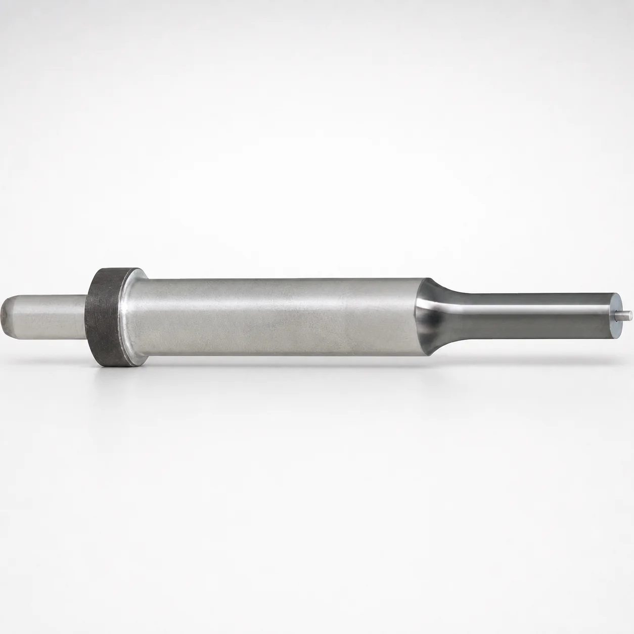
ISO Standard Steel RX Coating Ejector Punches with Locating Dowel Holes
Ejector Punches with Locating Dowel Holes (RX coating) (steel) are designed for repeatable part placement during mold assembly. The locating dowel holes enhance positional accuracy while supporting stable punch performance for long cycle operations.
- Locating dowel hole design improves precision alignment and reduces misplacement risk
- RX coating helps resist wear for consistent punch longevity in production
- Engineered for tight-tolerance assembly to support stable, repeatable ejection accuracy
- Suitable for die/mold applications that require accurate center guidance and reliable punch fit
Specifications
1232 configurations available
| Jector | Tip shape | B (Tip length) | D (Shank diameter) (mm) | P (Tip dimension) (mm) | L (L dimension) (mm) | LC(Full length change) | PC(Tip dimension change) (mm) | R(Tip corner R) (mm) | W(Tip dimension) | WC(Tip dimension change) (mm) | type |
|---|---|---|---|---|---|---|---|---|---|---|---|
| Standard type | Round | L | 10 | 3 ~ 9.99 | 70 ~ 120 | - | - | - | - | - | - |
| Standard type | Round | L | 10 | - | 70 ~ 120 | - | 2.8 ~ 3 | - | - | - | - |
| Standard type | Round | L | 10 | 3 ~ 9.99 | - | 34 ~ 119.9 | - | - | - | - | - |
| Standard type | Round | L | 10 | - | - | 34 ~ 119.9 | 2.8 ~ 3 | - | - | - | - |
| Standard type | Round | L | 13 | 6 ~ 12.99 | 70 ~ 120 | - | - | - | - | - | - |
| Standard type | Round | L | 13 | - | 70 ~ 120 | - | 5 ~ 6 | - | - | - | - |
| Standard type | Round | L | 13 | 6 ~ 12.99 | - | 34 ~ 119.9 | - | - | - | - | - |
| Standard type | Round | L | 13 | - | - | 34 ~ 119.9 | 5 ~ 6 | - | - | - | - |
| Standard type | Round | L | 16 | 10 ~ 15.99 | 70 ~ 120 | - | - | - | - | - | - |
| Standard type | Round | L | 16 | - | 70 ~ 120 | - | 8 ~ 10 | - | - | - | - |
| Standard type | Round | L | 16 | 10 ~ 15.99 | - | 34 ~ 119.9 | - | - | - | - | - |
| Standard type | Round | L | 16 | - | - | 34 ~ 119.9 | 8 ~ 10 | - | - | - | - |
| Standard type | Round | L | 20 | 13 ~ 19.99 | 70 ~ 120 | - | - | - | - | - | - |
| Standard type | Round | L | 20 | - | 70 ~ 120 | - | 9 ~ 13 | - | - | - | - |
| Standard type | Round | L | 20 | 13 ~ 19.99 | - | 34 ~ 119.9 | - | - | - | - | - |
| Standard type | Round | L | 20 | - | - | 34 ~ 119.9 | 9 ~ 13 | - | - | - | - |
| Standard type | Round | L | 25 | 18 ~ 24.99 | 70 ~ 120 | - | - | - | - | - | - |
| Standard type | Round | L | 25 | - | 70 ~ 120 | - | 9 ~ 18 | - | - | - | - |
| Standard type | Round | L | 25 | 18 ~ 24.99 | - | 34 ~ 119.9 | - | - | - | - | - |
| Standard type | Round | L | 25 | - | - | 34 ~ 119.9 | 9 ~ 18 | - | - | - | - |
| Standard type | Round | L | 32 | 20 ~ 31.99 | 70 ~ 120 | - | - | - | - | - | - |
| Standard type | Round | L | 32 | - | 70 ~ 120 | - | 15 ~ 19.99 | - | - | - | - |
| Standard type | Round | L | 32 | 20 ~ 31.99 | - | 47 ~ 119.9 | - | - | - | - | - |
| Standard type | Round | L | 32 | - | - | 47 ~ 119.9 | 15 ~ 19.99 | - | - | - | - |
| Standard type | Round | L | 38 | 28 ~ 37.99 | 70 ~ 120 | - | - | - | - | - | - |
| Standard type | Round | L | 38 | - | 70 ~ 120 | - | 23 ~ 27.99 | - | - | - | - |
| Standard type | Round | L | 38 | 28 ~ 37.99 | - | 47 ~ 119.9 | - | - | - | - | - |
| Standard type | Round | L | 38 | - | - | 47 ~ 119.9 | 23 ~ 27.99 | - | - | - | - |
| Standard type | Round | L | 45 | 35 ~ 44.99 | 70 ~ 120 | - | - | - | - | - | - |
| Standard type | Round | L | 45 | - | 70 ~ 120 | - | 30 ~ 34.99 | - | - | - | - |
| Standard type | Round | L | 45 | 35 ~ 44.99 | - | 47 ~ 119.9 | - | - | - | - | - |
| Standard type | Round | L | 45 | - | - | 47 ~ 119.9 | 30 ~ 34.99 | - | - | - | - |
| Standard type | Round | S | 10 | 3 ~ 9.99 | 60 ~ 120 | - | - | - | - | - | - |
| Standard type | Round | S | 10 | - | 60 ~ 120 | - | 2.8 ~ 2.99 | - | - | - | - |
| Standard type | Round | S | 10 | 3 ~ 9.99 | - | 34 ~ 119.9 | - | - | - | - | - |
| Standard type | Round | S | 10 | - | - | 34 ~ 119.9 | 2.8 ~ 2.99 | - | - | - | - |
| Standard type | Round | S | 13 | 6 ~ 12.99 | 60 ~ 120 | - | - | - | - | - | - |
| Standard type | Round | S | 13 | - | 60 ~ 120 | - | 5 ~ 6 | - | - | - | - |
| Standard type | Round | S | 13 | 6 ~ 12.99 | - | 34 ~ 119.9 | - | - | - | - | - |
| Standard type | Round | S | 13 | - | - | 34 ~ 119.9 | 5 ~ 6 | - | - | - | - |
| Standard type | Round | S | 16 | 10 ~ 15.99 | 60 ~ 120 | - | - | - | - | - | - |
| Standard type | Round | S | 16 | - | 60 ~ 120 | - | 8 ~ 10 | - | - | - | - |
| Standard type | Round | S | 16 | 10 ~ 15.99 | - | 34 ~ 119.9 | - | - | - | - | - |
| Standard type | Round | S | 16 | - | - | 34 ~ 119.9 | 8 ~ 10 | - | - | - | - |
| Standard type | Round | S | 20 | 13 ~ 19.99 | 60 ~ 120 | - | - | - | - | - | - |
| Standard type | Round | S | 20 | - | 60 ~ 120 | - | 9 ~ 13 | - | - | - | - |
| Standard type | Round | S | 20 | 13 ~ 19.99 | - | 34 ~ 119.9 | - | - | - | - | - |
| Standard type | Round | S | 20 | - | - | 34 ~ 119.9 | 9 ~ 13 | - | - | - | - |
| Standard type | Round | S | 25 | 18 ~ 24.99 | 60 ~ 120 | - | - | - | - | - | - |
| Standard type | Round | S | 25 | - | 60 ~ 120 | - | 9 ~ 18 | - | - | - | - |
Product Guide
Application Scenarios+
RX-coated ejector punches with locating dowel holes are used inside precision injection molds where ejector alignment directly impacts part release accuracy. The locating dowel holes support repeatable center guidance during assembly, helping engineers maintain positional stability under high cycle loads.
Common scenarios include:
- Automotive connector and housing molds: Use the standard or spring reinforced type for dependable ejection while the RX coating supports wear resistance at the punch/cavity interface during long runs.
- Appliance and consumer device housings: Tip options (round, rectangle, oblong, and double-flatted forms) help match contact geometry to gate/runner layouts, while stable fit reduces misplacement risk during tool start-up.
- Medical device components: The dowel-hole locating feature improves assembly repeatability, supporting consistent ejection accuracy for tight-tolerance parts.
This variant is suited when precise punch fit and guided assembly alignment are required to protect mold geometry and keep ejection performance consistent over time.
Material & Process Details+
This series specifies ISO Standard Steel with an RX coating applied to the ejector punch working surface. While the exact steel grade and coating thickness are not provided in the data, the engineering intent is clear: the base steel provides structural toughness for punching loads, and the RX coating improves surface wear resistance for repeatable ejection.
- Heat treatment state: Not stated in the provided specifications; however, ISO standard steel ejector components are typically supplied in a hardened/tempered condition suitable for mold service.
- Wear vs. toughness trade-off: Harder, wear-focused surface behavior from the RX coating helps resist abrasion, while the steel core supports punch toughness to reduce risk of chipping or deformation.
- Manufacturing process: Produced as precision punches with integral locating dowel hole geometry for guided assembly and stable fit.
If you require a specific hardness level (HRC) or a nitriding/quenched-and-tempered condition, confirm the exact steel grade and heat-treatment certificate for your build before quoting.
Sizing & Selection Guide+
Select dimensions by matching the ejector punch geometry to the mold cavity/core layout and the required ejection contact area. Start with the shank diameter D (10–45 mm) to ensure correct guidance within the ejector plate/bushing system.
- Tip geometry: Choose the tip shape (round, rectangle, oblong, double flatted round, radius rectangle) and size parameters P (3–35 mm), W (3–9 mm), and corner radius R (0.15 mm) to match part geometry and minimize stress concentrations.
- Length and travel accommodation: Use the L dimension ranges (70–120, 60–120, 80–120, or 100–120 mm) and confirm LC (34–72) and PC (2.8–30 mm) to align with available mold space and dimensional change requirements.
- Tip length B: Select B (L, S, X) for the required reach while maintaining clearance to surrounding tooling.
Because only dimension ranges are given (no explicit tolerances), verify fit by checking clearances against your ejector guide and plate hole tolerances in the mold design.
Frequently Asked Questions
How do I choose the correct ejector punch shank diameter (D) for my ejector guide system?+
Select D (10–45 mm) to match the diameter of your ejector guide/bushing and the corresponding receiving hole in the ejector plate. If D is mismatched, you risk excessive side clearance (misalignment) or binding during tool thermal cycles. Confirm that the assembled stroke and guidance length are compatible with your mold design envelope.
Which tip shapes and dimensions (P, W, R) are best for reducing marks on the molded part?+
Choose the tip shape (round, rectangle, oblong, double flatted round, or radius rectangle) based on the contact face and desired load distribution. Use P (3–35 mm) and W (3–9 mm) to size the contact area, and apply the specified corner radius R (0.15 mm) to manage stress concentration at the punch edge. Smaller or more controlled contact geometries generally help limit cosmetic marks.
How should I interpret the length parameters L, LC, and PC when designing for dimensional change?+
The series provides multiple length-related parameters: L (70–120, 60–120, 80–120, or 100–120 mm), LC (34–72), and PC (2.8–30 mm). Use these to ensure the punch length and expected dimensional change fit your mold cavity/core stack and available space through assembly and service. If your tool accounts for specific shrinkage or wear allowances, align your design margins to LC/PC values.
When should I select Standard type versus Spring reinforced type for ejector applications?+
The data indicates two variants: Standard type and Spring reinforced type. Use the spring reinforced option when you expect higher rebound risk, uneven loading, or need improved compliance during ejection. For stable, predictable loads with tight locating, the standard type is typically sufficient—especially where the locating dowel holes provide alignment.
What is the role of the locating dowel holes in mold assembly compatibility?+
The locating dowel holes are intended to improve precision alignment and reduce misplacement risk during tool assembly. This helps maintain stable punch fit, which supports consistent ejection accuracy over long cycle operations. Ensure your mold has matching dowel features and the receiving geometry allows correct seating without interference.
Related Products

Metric Center Dowel Ejector Punches (SKD11 Equivalent)

Dicoat Treatment SKD11 Steel Center Dowel Ejector Punches - Metric

Center Dowel Ejector Punches - Metric, XCN TiCN Coating

DIN Standard SKD11 Steel Gas Release Single-Stepped Ejector Punches

Center Dowel Ejector Punches with Locating Dowel Hole

DIN Standard TiCN Center Dowel Ejector Punches
Need Custom Specifications?
Our engineering team can help with custom configurations, material selection, and volume pricing.