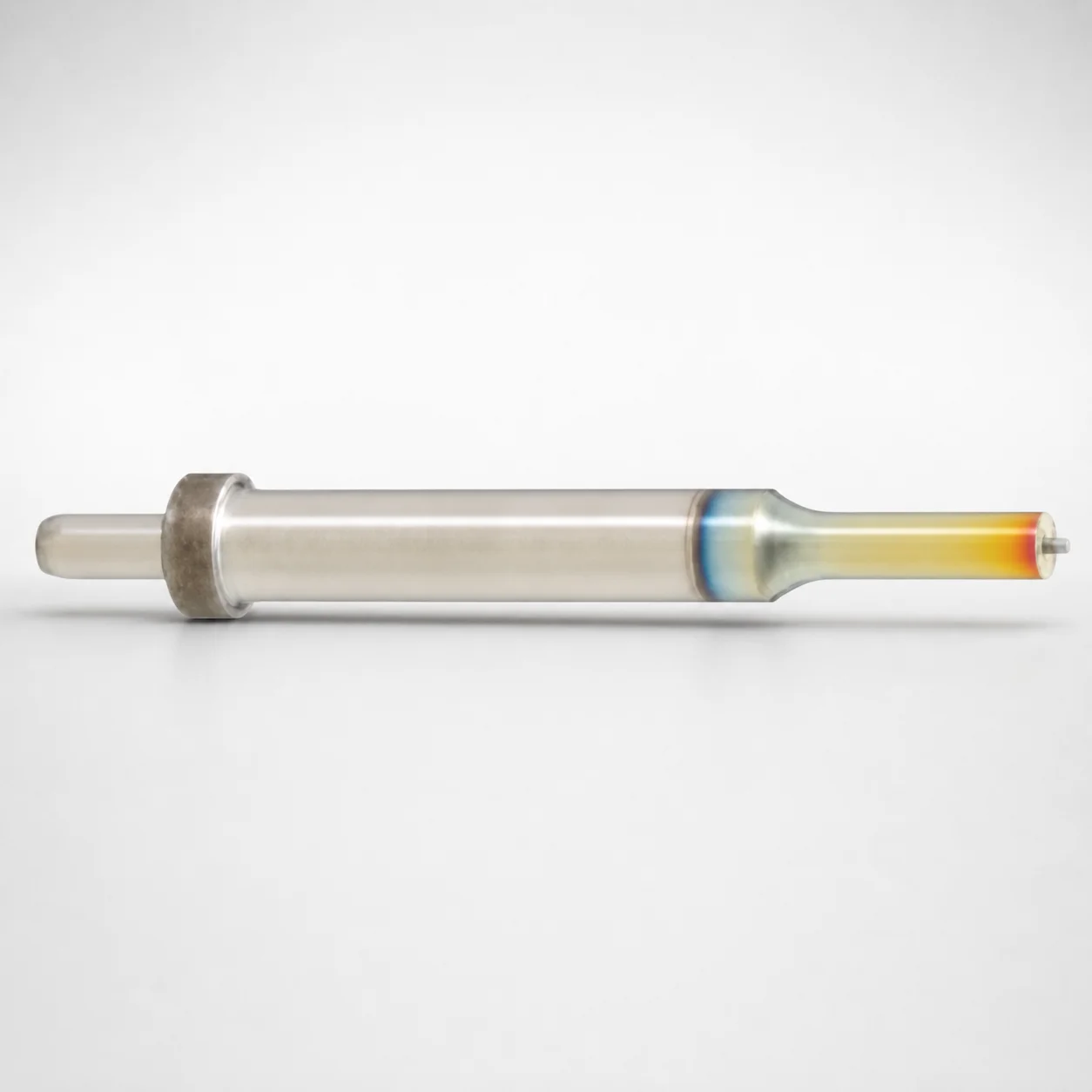
DLC Coating Gas Release Single-Stepped Center Dowel Ejector Punches
Gas release single-stepped center dowel ejector punches (D2 equivalent, SKD11 equivalent) are engineered for precise locating with a dedicated center dowel hole and a DLC-coated surface to support consistent ejection in production. The single-stepped shank geometry helps maintain stable tool positioning during cycling.
- Built-in locating dowel hole for accurate alignment in ejector systems
- DLC (XCD) coating improves wear resistance and reduces galling risk
- m5 shank diameter tolerance supports controlled fit and repeatability
- Hardened tool steel design for die casting and high-cycle stamping applications
Specifications
1232 configurations available
| Jector | Tip shape | B (Tip length) | D (Shank diameter) (mm) | P (Tip dimension) (mm) | L (L dimension) (mm) | LC (Full length alteration) (mm) | PC (Tip dimension alteration) (mm) | R (Tip corner R) (mm) | W (Tip dimension) (mm) | WC (Tip dimension alteration) (mm) | type |
|---|---|---|---|---|---|---|---|---|---|---|---|
| Standard type | Round | L | 10 | 3 ~ 9.99 | 70 ~ 120 | - | - | - | - | - | - |
| Standard type | Round | L | 10 | - | 70 ~ 120 | - | 2.8 ~ 3 | - | - | - | - |
| Standard type | Round | L | 10 | 3 ~ 9.99 | - | 34 ~ 119.9 | - | - | - | - | - |
| Standard type | Round | L | 10 | - | - | 34 ~ 119.9 | 2.8 ~ 3 | - | - | - | - |
| Standard type | Round | L | 13 | 6 ~ 12.99 | 70 ~ 120 | - | - | - | - | - | - |
| Standard type | Round | L | 13 | - | 70 ~ 120 | - | 5 ~ 6 | - | - | - | - |
| Standard type | Round | L | 13 | 6 ~ 12.99 | - | 34 ~ 119.9 | - | - | - | - | - |
| Standard type | Round | L | 13 | - | - | 34 ~ 119.9 | 5 ~ 6 | - | - | - | - |
| Standard type | Round | L | 16 | 10 ~ 15.99 | 70 ~ 120 | - | - | - | - | - | - |
| Standard type | Round | L | 16 | - | 70 ~ 120 | - | 8 ~ 10 | - | - | - | - |
| Standard type | Round | L | 16 | 10 ~ 15.99 | - | 34 ~ 119.9 | - | - | - | - | - |
| Standard type | Round | L | 16 | - | - | 34 ~ 119.9 | 8 ~ 10 | - | - | - | - |
| Standard type | Round | L | 20 | 13 ~ 19.99 | 70 ~ 120 | - | - | - | - | - | - |
| Standard type | Round | L | 20 | - | 70 ~ 120 | - | 9 ~ 13 | - | - | - | - |
| Standard type | Round | L | 20 | 13 ~ 19.99 | - | 34 ~ 119.9 | - | - | - | - | - |
| Standard type | Round | L | 20 | - | - | 34 ~ 119.9 | 9 ~ 13 | - | - | - | - |
| Standard type | Round | L | 25 | 18 ~ 24.99 | 70 ~ 120 | - | - | - | - | - | - |
| Standard type | Round | L | 25 | - | 70 ~ 120 | - | 9 ~ 18 | - | - | - | - |
| Standard type | Round | L | 25 | 18 ~ 24.99 | - | 34 ~ 119.9 | - | - | - | - | - |
| Standard type | Round | L | 25 | - | - | 34 ~ 119.9 | 9 ~ 18 | - | - | - | - |
| Standard type | Round | L | 32 | 20 ~ 31.99 | 70 ~ 120 | - | - | - | - | - | - |
| Standard type | Round | L | 32 | - | 70 ~ 120 | - | 15 ~ 19.99 | - | - | - | - |
| Standard type | Round | L | 32 | 20 ~ 31.99 | - | 47 ~ 119.9 | - | - | - | - | - |
| Standard type | Round | L | 32 | - | - | 47 ~ 119.9 | 15 ~ 19.99 | - | - | - | - |
| Standard type | Round | L | 38 | 28 ~ 37.99 | 70 ~ 120 | - | - | - | - | - | - |
| Standard type | Round | L | 38 | - | 70 ~ 120 | - | 23 ~ 27.99 | - | - | - | - |
| Standard type | Round | L | 38 | 28 ~ 37.99 | - | 47 ~ 119.9 | - | - | - | - | - |
| Standard type | Round | L | 38 | - | - | 47 ~ 119.9 | 23 ~ 27.99 | - | - | - | - |
| Standard type | Round | L | 45 | 35 ~ 44.99 | 70 ~ 120 | - | - | - | - | - | - |
| Standard type | Round | L | 45 | - | 70 ~ 120 | - | 30 ~ 34.99 | - | - | - | - |
| Standard type | Round | L | 45 | 35 ~ 44.99 | - | 47 ~ 119.9 | - | - | - | - | - |
| Standard type | Round | L | 45 | - | - | 47 ~ 119.9 | 30 ~ 34.99 | - | - | - | - |
| Standard type | Round | S | 10 | 3 ~ 9.99 | 60 ~ 120 | - | - | - | - | - | - |
| Standard type | Round | S | 10 | - | 60 ~ 120 | - | 2.8 ~ 2.99 | - | - | - | - |
| Standard type | Round | S | 10 | 3 ~ 9.99 | - | 34 ~ 119.9 | - | - | - | - | - |
| Standard type | Round | S | 10 | - | - | 34 ~ 119.9 | 2.8 ~ 2.99 | - | - | - | - |
| Standard type | Round | S | 13 | 6 ~ 12.99 | 60 ~ 120 | - | - | - | - | - | - |
| Standard type | Round | S | 13 | - | 60 ~ 120 | - | 5 ~ 6 | - | - | - | - |
| Standard type | Round | S | 13 | 6 ~ 12.99 | - | 34 ~ 119.9 | - | - | - | - | - |
| Standard type | Round | S | 13 | - | - | 34 ~ 119.9 | 5 ~ 6 | - | - | - | - |
| Standard type | Round | S | 16 | 10 ~ 15.99 | 60 ~ 120 | - | - | - | - | - | - |
| Standard type | Round | S | 16 | - | 60 ~ 120 | - | 8 ~ 10 | - | - | - | - |
| Standard type | Round | S | 16 | 10 ~ 15.99 | - | 34 ~ 119.9 | - | - | - | - | - |
| Standard type | Round | S | 16 | - | - | 34 ~ 119.9 | 8 ~ 10 | - | - | - | - |
| Standard type | Round | S | 20 | 13 ~ 19.99 | 60 ~ 120 | - | - | - | - | - | - |
| Standard type | Round | S | 20 | - | 60 ~ 120 | - | 9 ~ 13 | - | - | - | - |
| Standard type | Round | S | 20 | 13 ~ 19.99 | - | 34 ~ 119.9 | - | - | - | - | - |
| Standard type | Round | S | 20 | - | - | 34 ~ 119.9 | 9 ~ 13 | - | - | - | - |
| Standard type | Round | S | 25 | 18 ~ 24.99 | 60 ~ 120 | - | - | - | - | - | - |
| Standard type | Round | S | 25 | - | 60 ~ 120 | - | 9 ~ 18 | - | - | - | - |
Product Guide
Application Scenarios+
Gas-release single-stepped center dowel ejector punches are used in injection mold tooling and progressive die sets where ejector force must be consistent and parts must release reliably. The center dowel hole provides positive locating inside the ejector system, helping prevent punch-to-cavity misalignment during high cycle operation.
- Thin-wall plastic housings & snap-fit parts: The DLC-coated surface supports smoother die ejection and helps reduce galling/adhesion on sliding interfaces, improving cycle-to-cycle repeatability.
- Automotive interior/exterior components: The single-stepped geometry stabilizes tool positioning under varying part stiffness, while the dowel locating improves alignment for multi-cavity or sequential ejector stages.
- High-cycle stamping/die casting auxiliaries: Hardened tool steel and wear-resistant coating are suited to frequent contact, where stable locating and reduced surface wear extend tool life.
Variant selection supports different ejector designs via standard or spring reinforced Jector types, enabling tuning for return behavior and load conditions.
Material & Process Details+
The provided description specifies a D2 equivalent hardened tool steel (also referenced as SKD11 equivalent) with DLC (XCD) coating for improved wear performance. D2/SKD11 is typically selected for its balance of high wear resistance and adequate toughness, which is critical for locating punches that experience repeated sliding and ejection forces.
- Coating: DLC (XCD) forms a low-friction, wear-resistant surface to reduce galling and promote smoother ejection.
- Heat treatment state: The product is described as hardened tool steel for stable locating and production durability.
- Hardness/transition: The exact HRC value is not provided in the input data; however, hardened D2/SKD11 generally implies a high-hardness condition optimized for wear, with toughness traded against impact resistance.
- Material comparison: Within this family, choosing D2/SKD11 over softer tool steels improves wear life at the cost of requiring controlled feed/edge design to avoid chipping.
Sizing & Selection Guide+
To select the correct gas-release ejector punch, start by matching the shank diameter D to your ejector bushing/guide and alignment stack. This product supports D = 10 ~ 45 mm, and the shank is indicated as m5 shank diameter tolerance, so your mating part should use an appropriate m5 fit strategy to ensure controlled guidance without binding.
Next, size the working end: choose the tip dimension P within 3 ~ 35 mm and select the tip shape (Round, Rectangle, Oblong, Double flatted round, Radius rectangle) to match cavity geometry. The tip length B is configurable as L, S, or X, and overall length is selected from the provided L range options (70–120, 60–120, 80–120, 100–120 mm) depending on the build-up required.
- Confirm LC (34 ~ 72 mm) and PC (2.8 ~ 30 mm) against your ejector travel and clearance requirements.
- Use the available corner radius R = 0.15 mm and tip width W (3 ~ 9 mm) to maintain consistent contact and avoid localized stress.
- If your design requires a specific height stack, select the matching full length alteration (LC) to maintain correct stand-off and part release timing.
Frequently Asked Questions
Is this ejector punch made from D2 or SKD11, and what does that mean for wear vs. toughness?+
How does the DLC (XCD) coating affect die ejection reliability?+
What shank diameter options are available, and what tolerance should I design for?+
Which tip geometries can I choose, and how do I map tip size to the cavity/core contact area?+
What is the difference between standard and spring reinforced Jector types for this punch family?+
Related Products

Metric Center Dowel Ejector Punches (SKD11 Equivalent)

Dicoat Treatment SKD11 Steel Center Dowel Ejector Punches - Metric

Center Dowel Ejector Punches - Metric, XCN TiCN Coating

DIN Standard SKD11 Steel Gas Release Single-Stepped Ejector Punches

Center Dowel Ejector Punches with Locating Dowel Hole

DIN Standard TiCN Center Dowel Ejector Punches
Need Custom Specifications?
Our engineering team can help with custom configurations, material selection, and volume pricing.