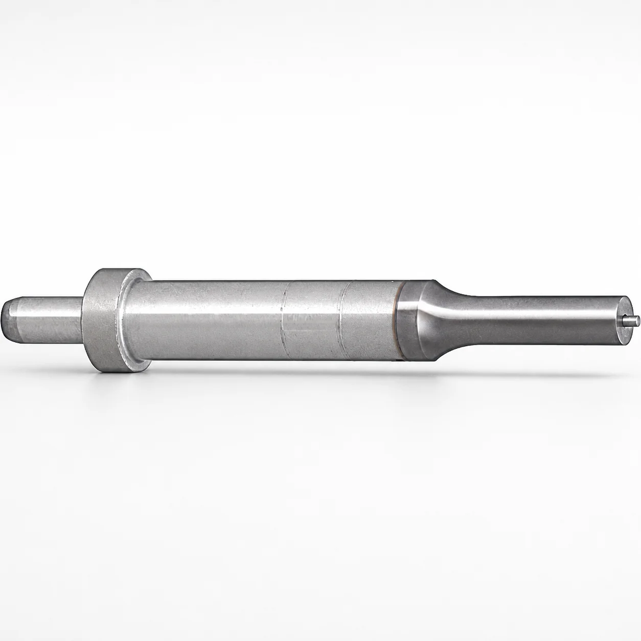
Ejector Punches with Locating Dowel Holes - HX Coating
Ejector Punches with Locating Dowel Holes - HX Coating are designed for precise positioning in tooling builds, improving alignment during punch ejection. The locating dowel holes support stable repeatability to help protect critical components in demanding machining cycles.
- Built-in locating dowel holes enhance punch-to-plate positioning accuracy
- HX coating supports wear reduction for long-running production
- Stable geometry helps maintain consistent ejection performance in assembly
- Suitable for high-volume dies requiring reliable alignment repeatability
Specifications
1232 configurations available
| Jector | Tip shape | B (Tip length) | D (Shank diameter) (mm) | P (Tip dimension) (mm) | L (L dimension) (mm) | LC(Full length change) | PC(Tip dimension change) (mm) | R(Tip corner R) (mm) | W(Tip dimension) | WC(Tip dimension change) (mm) | type |
|---|---|---|---|---|---|---|---|---|---|---|---|
| Standard type | Round | L | 10 | 3 ~ 9.99 | 70 ~ 120 | - | - | - | - | - | - |
| Standard type | Round | L | 10 | - | 70 ~ 120 | - | 2.8 ~ 3 | - | - | - | - |
| Standard type | Round | L | 10 | 3 ~ 9.99 | - | 34 ~ 119.9 | - | - | - | - | - |
| Standard type | Round | L | 10 | - | - | 34 ~ 119.9 | 2.8 ~ 3 | - | - | - | - |
| Standard type | Round | L | 13 | 6 ~ 12.99 | 70 ~ 120 | - | - | - | - | - | - |
| Standard type | Round | L | 13 | - | 70 ~ 120 | - | 5 ~ 6 | - | - | - | - |
| Standard type | Round | L | 13 | 6 ~ 12.99 | - | 34 ~ 119.9 | - | - | - | - | - |
| Standard type | Round | L | 13 | - | - | 34 ~ 119.9 | 5 ~ 6 | - | - | - | - |
| Standard type | Round | L | 16 | 10 ~ 15.99 | 70 ~ 120 | - | - | - | - | - | - |
| Standard type | Round | L | 16 | - | 70 ~ 120 | - | 8 ~ 10 | - | - | - | - |
| Standard type | Round | L | 16 | 10 ~ 15.99 | - | 34 ~ 119.9 | - | - | - | - | - |
| Standard type | Round | L | 16 | - | - | 34 ~ 119.9 | 8 ~ 10 | - | - | - | - |
| Standard type | Round | L | 20 | 13 ~ 19.99 | 70 ~ 120 | - | - | - | - | - | - |
| Standard type | Round | L | 20 | - | 70 ~ 120 | - | 9 ~ 13 | - | - | - | - |
| Standard type | Round | L | 20 | 13 ~ 19.99 | - | 34 ~ 119.9 | - | - | - | - | - |
| Standard type | Round | L | 20 | - | - | 34 ~ 119.9 | 9 ~ 13 | - | - | - | - |
| Standard type | Round | L | 25 | 18 ~ 24.99 | 70 ~ 120 | - | - | - | - | - | - |
| Standard type | Round | L | 25 | - | 70 ~ 120 | - | 9 ~ 18 | - | - | - | - |
| Standard type | Round | L | 25 | 18 ~ 24.99 | - | 34 ~ 119.9 | - | - | - | - | - |
| Standard type | Round | L | 25 | - | - | 34 ~ 119.9 | 9 ~ 18 | - | - | - | - |
| Standard type | Round | L | 32 | 20 ~ 31.99 | 70 ~ 120 | - | - | - | - | - | - |
| Standard type | Round | L | 32 | - | 70 ~ 120 | - | 15 ~ 19.99 | - | - | - | - |
| Standard type | Round | L | 32 | 20 ~ 31.99 | - | 47 ~ 119.9 | - | - | - | - | - |
| Standard type | Round | L | 32 | - | - | 47 ~ 119.9 | 15 ~ 19.99 | - | - | - | - |
| Standard type | Round | L | 38 | 28 ~ 37.99 | 70 ~ 120 | - | - | - | - | - | - |
| Standard type | Round | L | 38 | - | 70 ~ 120 | - | 23 ~ 27.99 | - | - | - | - |
| Standard type | Round | L | 38 | 28 ~ 37.99 | - | 47 ~ 119.9 | - | - | - | - | - |
| Standard type | Round | L | 38 | - | - | 47 ~ 119.9 | 23 ~ 27.99 | - | - | - | - |
| Standard type | Round | L | 45 | 35 ~ 44.99 | 70 ~ 120 | - | - | - | - | - | - |
| Standard type | Round | L | 45 | - | 70 ~ 120 | - | 30 ~ 34.99 | - | - | - | - |
| Standard type | Round | L | 45 | 35 ~ 44.99 | - | 47 ~ 119.9 | - | - | - | - | - |
| Standard type | Round | L | 45 | - | - | 47 ~ 119.9 | 30 ~ 34.99 | - | - | - | - |
| Standard type | Round | S | 10 | 3 ~ 9.99 | 60 ~ 120 | - | - | - | - | - | - |
| Standard type | Round | S | 10 | - | 60 ~ 120 | - | 2.8 ~ 2.99 | - | - | - | - |
| Standard type | Round | S | 10 | 3 ~ 9.99 | - | 34 ~ 119.9 | - | - | - | - | - |
| Standard type | Round | S | 10 | - | - | 34 ~ 119.9 | 2.8 ~ 2.99 | - | - | - | - |
| Standard type | Round | S | 13 | 6 ~ 12.99 | 60 ~ 120 | - | - | - | - | - | - |
| Standard type | Round | S | 13 | - | 60 ~ 120 | - | 5 ~ 6 | - | - | - | - |
| Standard type | Round | S | 13 | 6 ~ 12.99 | - | 34 ~ 119.9 | - | - | - | - | - |
| Standard type | Round | S | 13 | - | - | 34 ~ 119.9 | 5 ~ 6 | - | - | - | - |
| Standard type | Round | S | 16 | 10 ~ 15.99 | 60 ~ 120 | - | - | - | - | - | - |
| Standard type | Round | S | 16 | - | 60 ~ 120 | - | 8 ~ 10 | - | - | - | - |
| Standard type | Round | S | 16 | 10 ~ 15.99 | - | 34 ~ 119.9 | - | - | - | - | - |
| Standard type | Round | S | 16 | - | - | 34 ~ 119.9 | 8 ~ 10 | - | - | - | - |
| Standard type | Round | S | 20 | 13 ~ 19.99 | 60 ~ 120 | - | - | - | - | - | - |
| Standard type | Round | S | 20 | - | 60 ~ 120 | - | 9 ~ 13 | - | - | - | - |
| Standard type | Round | S | 20 | 13 ~ 19.99 | - | 34 ~ 119.9 | - | - | - | - | - |
| Standard type | Round | S | 20 | - | - | 34 ~ 119.9 | 9 ~ 13 | - | - | - | - |
| Standard type | Round | S | 25 | 18 ~ 24.99 | 60 ~ 120 | - | - | - | - | - | - |
| Standard type | Round | S | 25 | - | 60 ~ 120 | - | 9 ~ 18 | - | - | - | - |
Product Guide
Application Scenarios+
Injection mold ejection systems use these ejector punches to transfer force from the ejection mechanism to the molded part with stable punch-to-plate alignment. The locating dowel holes help maintain repeatable positioning between punches and the ejector plate, reducing the risk of scuffing or uneven ejection in long production runs.
- Automotive connector and bracket tooling: high-cycle ejection benefits from the HX coating, which is intended to reduce wear under abrasive, continuous contact conditions.
- Consumer electronics housings: the locating features improve alignment consistency across multiple cavities, helping protect tight-tolerance part surfaces during part release.
- General-purpose multi-cavity dies: spring-reinforced or standard variants support robust operation when there are packaging constraints and frequent maintenance intervals.
Choose the tip shape and shank diameter to match the part release geometry while relying on the dowel holes to keep ejection behavior consistent.
Material & Process Details+
The provided series information does not specify a steel grade or numeric heat-treatment hardness (e.g., HRC), so material properties are best treated as application-dependent for this listing.
- Coating (HX): HX coating is used to reduce wear during high-volume production where ejector punches experience repeated sliding/impact cycles against ejector plate and wear surfaces.
- Manufacturing approach: ejector punches with precision dowel-hole location are typically produced by turning/grinding for diameter and length control, followed by coating application for wear reduction.
- Trade-off: wear resistance from the coating supports longevity, while dimensional stability depends on correct sizing and maintaining clearances in the ejector plate.
If your build requires a known wear/toughness balance, request the exact steel specification and heat-treatment condition for the selected variant of this series.
Sizing & Selection Guide+
Correct selection of an ejector punch is primarily about matching the shank diameter (D = 10 ~ 45 mm) and the working tip geometry to your cavity/core and ejection stroke design. Use the tip dimension (P = 3 ~ 35 mm), tip length (B = L, S, X), and tip width (W = 3 ~ 9 mm) to match the part’s release feature and prevent localized stress concentrations.
- Length selection: choose L (L dimension) from 70~120, 60~120, 80~120, or 100~120 depending on the required overall punch travel envelope.
- Full-length change (LC = 34 ~ 72) and tip change (PC = 2.8 ~ 30) should be checked against your expected dimensional changes from assembly and any controlled wear allowance.
- Corner radius: select R = 0.15 mm to support consistent contact without sharp edges.
Because locating dowel holes are part of alignment, ensure the ejector plate’s dowel-hole pattern matches the series’ locating design, and validate fit with your plate and stripper design tolerances.
Frequently Asked Questions
Which dimensions should I prioritize when selecting this ejector punch with locating dowel holes for a specific cavity layout?+
Prioritize D (shank diameter 10 ~ 45 mm) and P (tip dimension 3 ~ 35 mm) first, since these determine fit and contact area. Then match L (70~120, 60~120, 80~120, or 100~120) to your available ejection stroke envelope. Finally, choose the tip form (round/rectangle/oblong/double flatted/radius rectangle) and B (L/S/X) to suit the part release geometry.
How do the HX coating and the locating dowel holes work together to reduce issues in high-volume ejection?+
The HX coating is intended to reduce wear during long-running, high-cycle production. The locating dowel holes improve punch-to-plate positioning repeatability, which helps keep ejection paths consistent. Together, they reduce the likelihood of misalignment-related scuffing and uneven load during part release.
What are the key constraints when choosing between standard and spring reinforced ejector punch variants?+
This series lists two Jector types: standard type and spring reinforced type. Select the spring reinforced variant when your design needs additional compliance to handle minor deflection or variations during ejection. Confirm that the overall L (70~120, 60~120, 80~120, or 100~120) still fits your tool’s available space.
How should I interpret LC (full length change) and PC (tip dimension change) during design for wear and dimensional shift?+
The listing provides LC (34 ~ 72) and PC (2.8 ~ 30 mm) ranges, which indicate allowable or modeled dimensional change characteristics. When designing clearances and alignment, ensure these change ranges align with your maintenance strategy and required performance window. Use your ejector plate and guide design tolerances to accommodate the expected change without binding.
Is the tip corner radius fixed for this series, and does it affect part release contact?+
For this series, the tip corner radius is given as R = 0.15 mm. This is intended to provide a controlled contact profile that avoids sharp transitions at the tip. When selecting the tip shape (e.g., radius rectangle vs. oblong), consider how the radius and width (W = 3 ~ 9 mm) interact with your molded geometry to ensure stable release.
Related Products

Metric Center Dowel Ejector Punches (SKD11 Equivalent)

Dicoat Treatment SKD11 Steel Center Dowel Ejector Punches - Metric

Center Dowel Ejector Punches - Metric, XCN TiCN Coating

DIN Standard SKD11 Steel Gas Release Single-Stepped Ejector Punches

Center Dowel Ejector Punches with Locating Dowel Hole

DIN Standard TiCN Center Dowel Ejector Punches
Need Custom Specifications?
Our engineering team can help with custom configurations, material selection, and volume pricing.