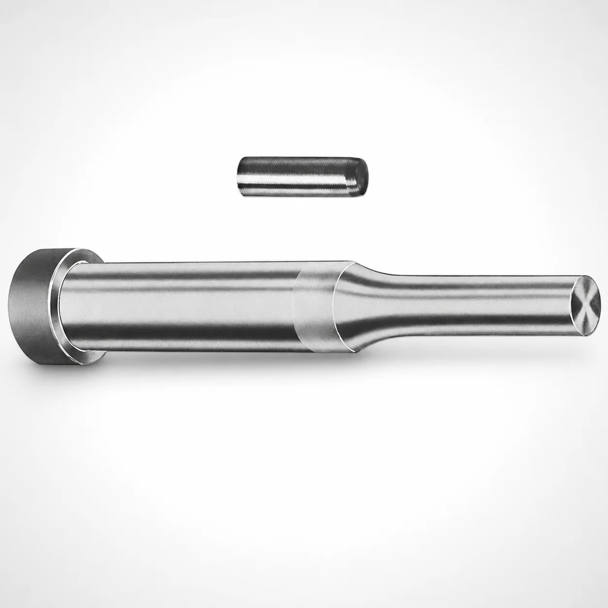
Center Dowel Regular Punches - Metric XVP Coating
Center Dowel Regular Punches - Metric XVP Coating are designed for accurate centering and stable punch guidance in progressive and transfer dies. The XVP coating supports reliable performance under repeated production cycles and helps manage wear on working surfaces.
- Regular center-dowel punch format improves positioning stability in die set assemblies
- XVP coating for enhanced surface durability in demanding stamping and forming operations
- Supports multiple tip profiles for matchable guidance geometry during setup
- Built for metric die applications where repeatable alignment and long service life matter
Specifications
228 configurations available
| Tip shape | D (Shank dia.) (mm) | L1 (Point Length) (mm) | L (Length) (mm) | P Dimension (mm) | W Dimension (mm) | R Dimension (mm) |
|---|---|---|---|---|---|---|
| H | 10 | 19 ~ 25 | 71 ~ 150 | 4 ~ 4.49 | 4 ~ 4.49 | - |
| H | 10 | 19 ~ 25 | 71 ~ 150 | 4 ~ 4.49 | 4.5 ~ 9.95 | - |
| H | 10 | 19 ~ 25 | 71 ~ 150 | 4.5 ~ 9.95 | 4 ~ 4.49 | - |
| H | 10 | 19 ~ 25 | 71 ~ 150 | 4.5 ~ 9.95 | 4.5 ~ 9.95 | - |
| H | 13 | 19 ~ 25 | 71 ~ 150 | 4 ~ 5.99 | 4 ~ 5.99 | - |
| H | 13 | 19 ~ 25 | 71 ~ 150 | 4 ~ 5.99 | 6 ~ 12.95 | - |
| H | 13 | 19 ~ 25 | 71 ~ 150 | 6 ~ 12.95 | 4 ~ 5.99 | - |
| H | 13 | 19 ~ 25 | 71 ~ 150 | 6 ~ 12.95 | 6 ~ 12.95 | - |
| H | 16 | 19 ~ 25 | 71 ~ 150 | 6 ~ 7.19 | 6 ~ 7.19 | - |
| H | 16 | 19 ~ 25 | 71 ~ 150 | 6 ~ 7.19 | 7.2 ~ 15.95 | - |
| H | 16 | 19 ~ 25 | 71 ~ 150 | 7.2 ~ 15.95 | 6 ~ 7.19 | - |
| H | 16 | 19 ~ 25 | 71 ~ 150 | 7.2 ~ 15.95 | 7.2 ~ 15.95 | - |
| H | 20 | 19 ~ 25 | 71 ~ 150 | 6 ~ 7.99 | 6 ~ 7.99 | - |
| H | 20 | 19 ~ 25 | 71 ~ 150 | 6 ~ 7.99 | 8 ~ 19.95 | - |
| H | 20 | 19 ~ 25 | 71 ~ 150 | 8 ~ 19.95 | 6 ~ 7.99 | - |
| H | 20 | 19 ~ 25 | 71 ~ 150 | 8 ~ 19.95 | 8 ~ 19.95 | - |
| H | 25 | 19 ~ 25 | 71 ~ 150 | 6 ~ 8.99 | 6 ~ 8.99 | - |
| H | 25 | 19 ~ 25 | 71 ~ 150 | 6 ~ 8.99 | 9 ~ 24.95 | - |
| H | 25 | 19 ~ 25 | 71 ~ 150 | 9 ~ 24.95 | 6 ~ 8.99 | - |
| H | 25 | 19 ~ 25 | 71 ~ 150 | 9 ~ 24.95 | 9 ~ 24.95 | - |
| H | 32 | 25 ~ 30 | 71 ~ 150 | 7.2 ~ 9.99 | 7.2 ~ 9.99 | - |
| H | 32 | 25 ~ 30 | 71 ~ 150 | 7.2 ~ 9.99 | 10 ~ 31.95 | - |
| H | 32 | 25 ~ 30 | 71 ~ 150 | 10 ~ 31.95 | 7.2 ~ 9.99 | - |
| H | 32 | 25 ~ 30 | 71 ~ 150 | 10 ~ 31.95 | 10 ~ 31.95 | - |
| J | 10 | 19 ~ 25 | 71 ~ 150 | 4 ~ 4.49 | 4 ~ 4.49 | - |
| J | 10 | 19 ~ 25 | 71 ~ 150 | 4 ~ 4.49 | 4.5 ~ 9.95 | - |
| J | 10 | 19 ~ 25 | 71 ~ 150 | 4.5 ~ 9.95 | 4 ~ 4.49 | - |
| J | 10 | 19 ~ 25 | 71 ~ 150 | 4.5 ~ 9.95 | 4.5 ~ 9.95 | - |
| J | 13 | 19 ~ 25 | 71 ~ 150 | 4 ~ 5.99 | 4 ~ 5.99 | - |
| J | 13 | 19 ~ 25 | 71 ~ 150 | 4 ~ 5.99 | 6 ~ 12.95 | - |
| J | 13 | 19 ~ 25 | 71 ~ 150 | 6 ~ 12.95 | 4 ~ 5.99 | - |
| J | 13 | 19 ~ 25 | 71 ~ 150 | 6 ~ 12.95 | 6 ~ 12.95 | - |
| J | 16 | 19 ~ 25 | 71 ~ 150 | 6 ~ 7.19 | 6 ~ 7.19 | - |
| J | 16 | 19 ~ 25 | 71 ~ 150 | 6 ~ 7.19 | 7.2 ~ 15.95 | - |
| J | 16 | 19 ~ 25 | 71 ~ 150 | 7.2 ~ 15.95 | 6 ~ 7.19 | - |
| J | 16 | 19 ~ 25 | 71 ~ 150 | 7.2 ~ 15.95 | 7.2 ~ 15.95 | - |
| J | 20 | 19 ~ 25 | 71 ~ 150 | 6 ~ 7.99 | 6 ~ 7.99 | - |
| J | 20 | 19 ~ 25 | 71 ~ 150 | 6 ~ 7.99 | 8 ~ 19.95 | - |
| J | 20 | 19 ~ 25 | 71 ~ 150 | 8 ~ 19.95 | 6 ~ 7.99 | - |
| J | 20 | 19 ~ 25 | 71 ~ 150 | 8 ~ 19.95 | 8 ~ 19.95 | - |
| J | 25 | 19 ~ 25 | 71 ~ 150 | 6 ~ 8.99 | 6 ~ 8.99 | - |
| J | 25 | 19 ~ 25 | 71 ~ 150 | 6 ~ 8.99 | 9 ~ 24.95 | - |
| J | 25 | 19 ~ 25 | 71 ~ 150 | 9 ~ 24.95 | 6 ~ 8.99 | - |
| J | 25 | 19 ~ 25 | 71 ~ 150 | 9 ~ 24.95 | 9 ~ 24.95 | - |
| J | 32 | 25 ~ 30 | 71 ~ 150 | 7.2 ~ 9.99 | 7.2 ~ 9.99 | - |
| J | 32 | 25 ~ 30 | 71 ~ 150 | 7.2 ~ 9.99 | 10 ~ 31.95 | - |
| J | 32 | 25 ~ 30 | 71 ~ 150 | 10 ~ 31.95 | 7.2 ~ 9.99 | - |
| J | 32 | 25 ~ 30 | 71 ~ 150 | 10 ~ 31.95 | 10 ~ 31.95 | - |
| K | 10 | 19 ~ 25 | 71 ~ 150 | 4 ~ 4.49 | 4 ~ 4.49 | 0.2 ~ 4.975 |
| K | 10 | 19 ~ 25 | 71 ~ 150 | 4 ~ 4.49 | 4.5 ~ 9.95 | 0.2 ~ 4.975 |
Product Guide
Application Scenarios+
Center-dowel punches are used to establish repeatable tool-to-tool alignment in progressive and transfer die sets, especially where large production runs demand consistent guidance. In connector, sensor, and terminal stamping lines, this punch style helps maintain centering and stable punch guidance during the dwell and strike phases, reducing positional drift between stations.
The XVP-coated working surfaces are well suited to die work that experiences frequent sliding contact with bushings, die plates, or feed mechanisms. The coating supports longer service life by helping manage wear on the guidance/impact regions under repeated cycles.
- Automotive stamping dies: Use metric shank diameters (10–32 mm) to match station guide geometries and maintain alignment across multiple successive operations.
- General industrial forming: Select the point length bands (L1: 19–25 mm or 25–30 mm) for controlled penetration and reliable locating without over-travel.
Material & Process Details+
The provided series data specifies an XVP coating for enhanced surface durability, but it does not include the underlying steel grade or hardness values. For selection, ensure your heat-treatment and coating system are compatible with your press loads and the expected sliding/wear conditions at the dowel interface.
In general die/punch applications, engineers balance wear resistance (typically improved by hardening and surface treatments) with toughness (to resist chipping under impact). XVP coatings are used to reduce friction and wear, improving tool life where guidance surfaces experience repeated micro-sliding.
- Coating effect: Greater durability at the guidance contact areas and improved resistance to wear-related dimensional change.
- Heat treatment state: Not specified in the current data—confirm with your technical sheet for whether the punch is pre-hardened or through-hardened.
Sizing & Selection Guide+
Use the series’ metric dimensions to match your die set’s locating system and guide requirements. Start with the shank diameter D = 10, 13, 16, 20, 25, or 32 mm—choose the one that corresponds to the receiving guide bushing or hole geometry in your die plate stack.
Next, select the point length band L1 = 19–25 mm or L1 = 25–30 mm based on how deep the punch must locate before effective contact/centering occurs in your sequence. The overall length is fixed at L = 71–150 mm, so verify total stack clearance (tool height allowance) in your die set.
- Tip shape: Choose from H, J, K, L, N, O, R, V, X, Y, Z to align with your required guidance/entry profile.
- Fine geometry: Confirm P (4–16 mm) and W (4–10 mm) plus R (0.2–4.975 / 0.2–6.475 / 0.2–7.975 / 0.2–9.975 / 0.2–12.475 / 0.2–15.975) to meet your cavity/core locating contours.
Apply standard die component fits/tolerances recommended for punching guide interfaces, and allow for coating thickness effects where your receiving bore limits are tight.
Frequently Asked Questions
Which shank diameter (D) options are available for this metric center dowel punch series?+
How do I choose the point length (L1) for correct locating in a progressive die station?+
What tip shapes are offered, and how does that impact punch guidance geometry?+
What do the P, W, and R dimensions control in the guidance/locating interface?+
Is the underlying steel grade or hardness specified for the XVP-coated dowel punch?+
Related Products

Metric Center Dowel Ejector Punches (SKD11 Equivalent)

Dicoat Treatment SKD11 Steel Center Dowel Ejector Punches - Metric

Center Dowel Ejector Punches - Metric, XCN TiCN Coating

DIN Standard SKD11 Steel Gas Release Single-Stepped Ejector Punches

Center Dowel Ejector Punches with Locating Dowel Hole

DIN Standard TiCN Center Dowel Ejector Punches
Need Custom Specifications?
Our engineering team can help with custom configurations, material selection, and volume pricing.