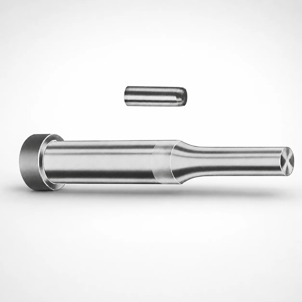
Center Dowel Regular Punches - Metric, XNAP Coating
Center Dowel Regular Punches - Metric, XNAP Coating are designed for repeatable locating and stable punch guidance in stamping and molding operations, helping reduce setup drift over production runs. The XNAP coating supports reliable wear resistance where friction and sliding are most demanding.
- Regular center dowel punch geometry for accurate workpiece positioning
- XNAP coating to improve surface durability under ejector duty
- Designed for consistent alignment using metric shank and point profiles
- Use in progressive dies, transfer tooling, and die-set applications
Specifications
228 configurations available
| Tip shape | D (Shank dia.) (mm) | L1 (Point Length) (mm) | L (Length) (mm) | P Dimension (mm) | W Dimension (mm) | R Dimension (mm) |
|---|---|---|---|---|---|---|
| H | 10 | 19 ~ 25 | 71 ~ 150 | 4 ~ 4.49 | 4 ~ 4.49 | - |
| H | 10 | 19 ~ 25 | 71 ~ 150 | 4 ~ 4.49 | 4.5 ~ 9.95 | - |
| H | 10 | 19 ~ 25 | 71 ~ 150 | 4.5 ~ 9.95 | 4 ~ 4.49 | - |
| H | 10 | 19 ~ 25 | 71 ~ 150 | 4.5 ~ 9.95 | 4.5 ~ 9.95 | - |
| H | 13 | 19 ~ 25 | 71 ~ 150 | 4 ~ 5.99 | 4 ~ 5.99 | - |
| H | 13 | 19 ~ 25 | 71 ~ 150 | 4 ~ 5.99 | 6 ~ 12.95 | - |
| H | 13 | 19 ~ 25 | 71 ~ 150 | 6 ~ 12.95 | 4 ~ 5.99 | - |
| H | 13 | 19 ~ 25 | 71 ~ 150 | 6 ~ 12.95 | 6 ~ 12.95 | - |
| H | 16 | 19 ~ 25 | 71 ~ 150 | 6 ~ 7.19 | 6 ~ 7.19 | - |
| H | 16 | 19 ~ 25 | 71 ~ 150 | 6 ~ 7.19 | 7.2 ~ 15.95 | - |
| H | 16 | 19 ~ 25 | 71 ~ 150 | 7.2 ~ 15.95 | 6 ~ 7.19 | - |
| H | 16 | 19 ~ 25 | 71 ~ 150 | 7.2 ~ 15.95 | 7.2 ~ 15.95 | - |
| H | 20 | 19 ~ 25 | 71 ~ 150 | 6 ~ 7.99 | 6 ~ 7.99 | - |
| H | 20 | 19 ~ 25 | 71 ~ 150 | 6 ~ 7.99 | 8 ~ 19.95 | - |
| H | 20 | 19 ~ 25 | 71 ~ 150 | 8 ~ 19.95 | 6 ~ 7.99 | - |
| H | 20 | 19 ~ 25 | 71 ~ 150 | 8 ~ 19.95 | 8 ~ 19.95 | - |
| H | 25 | 19 ~ 25 | 71 ~ 150 | 6 ~ 8.99 | 6 ~ 8.99 | - |
| H | 25 | 19 ~ 25 | 71 ~ 150 | 6 ~ 8.99 | 9 ~ 24.95 | - |
| H | 25 | 19 ~ 25 | 71 ~ 150 | 9 ~ 24.95 | 6 ~ 8.99 | - |
| H | 25 | 19 ~ 25 | 71 ~ 150 | 9 ~ 24.95 | 9 ~ 24.95 | - |
| H | 32 | 25 ~ 30 | 71 ~ 150 | 7.2 ~ 9.99 | 7.2 ~ 9.99 | - |
| H | 32 | 25 ~ 30 | 71 ~ 150 | 7.2 ~ 9.99 | 10 ~ 31.95 | - |
| H | 32 | 25 ~ 30 | 71 ~ 150 | 10 ~ 31.95 | 7.2 ~ 9.99 | - |
| H | 32 | 25 ~ 30 | 71 ~ 150 | 10 ~ 31.95 | 10 ~ 31.95 | - |
| J | 10 | 19 ~ 25 | 71 ~ 150 | 4 ~ 4.49 | 4 ~ 4.49 | - |
| J | 10 | 19 ~ 25 | 71 ~ 150 | 4 ~ 4.49 | 4.5 ~ 9.95 | - |
| J | 10 | 19 ~ 25 | 71 ~ 150 | 4.5 ~ 9.95 | 4 ~ 4.49 | - |
| J | 10 | 19 ~ 25 | 71 ~ 150 | 4.5 ~ 9.95 | 4.5 ~ 9.95 | - |
| J | 13 | 19 ~ 25 | 71 ~ 150 | 4 ~ 5.99 | 4 ~ 5.99 | - |
| J | 13 | 19 ~ 25 | 71 ~ 150 | 4 ~ 5.99 | 6 ~ 12.95 | - |
| J | 13 | 19 ~ 25 | 71 ~ 150 | 6 ~ 12.95 | 4 ~ 5.99 | - |
| J | 13 | 19 ~ 25 | 71 ~ 150 | 6 ~ 12.95 | 6 ~ 12.95 | - |
| J | 16 | 19 ~ 25 | 71 ~ 150 | 6 ~ 7.19 | 6 ~ 7.19 | - |
| J | 16 | 19 ~ 25 | 71 ~ 150 | 6 ~ 7.19 | 7.2 ~ 15.95 | - |
| J | 16 | 19 ~ 25 | 71 ~ 150 | 7.2 ~ 15.95 | 6 ~ 7.19 | - |
| J | 16 | 19 ~ 25 | 71 ~ 150 | 7.2 ~ 15.95 | 7.2 ~ 15.95 | - |
| J | 20 | 19 ~ 25 | 71 ~ 150 | 6 ~ 7.99 | 6 ~ 7.99 | - |
| J | 20 | 19 ~ 25 | 71 ~ 150 | 6 ~ 7.99 | 8 ~ 19.95 | - |
| J | 20 | 19 ~ 25 | 71 ~ 150 | 8 ~ 19.95 | 6 ~ 7.99 | - |
| J | 20 | 19 ~ 25 | 71 ~ 150 | 8 ~ 19.95 | 8 ~ 19.95 | - |
| J | 25 | 19 ~ 25 | 71 ~ 150 | 6 ~ 8.99 | 6 ~ 8.99 | - |
| J | 25 | 19 ~ 25 | 71 ~ 150 | 6 ~ 8.99 | 9 ~ 24.95 | - |
| J | 25 | 19 ~ 25 | 71 ~ 150 | 9 ~ 24.95 | 6 ~ 8.99 | - |
| J | 25 | 19 ~ 25 | 71 ~ 150 | 9 ~ 24.95 | 9 ~ 24.95 | - |
| J | 32 | 25 ~ 30 | 71 ~ 150 | 7.2 ~ 9.99 | 7.2 ~ 9.99 | - |
| J | 32 | 25 ~ 30 | 71 ~ 150 | 7.2 ~ 9.99 | 10 ~ 31.95 | - |
| J | 32 | 25 ~ 30 | 71 ~ 150 | 10 ~ 31.95 | 7.2 ~ 9.99 | - |
| J | 32 | 25 ~ 30 | 71 ~ 150 | 10 ~ 31.95 | 10 ~ 31.95 | - |
| K | 10 | 19 ~ 25 | 71 ~ 150 | 4 ~ 4.49 | 4 ~ 4.49 | 0.2 ~ 4.975 |
| K | 10 | 19 ~ 25 | 71 ~ 150 | 4 ~ 4.49 | 4.5 ~ 9.95 | 0.2 ~ 4.975 |
Product Guide
Application Scenarios+
This center-dowel punch family is used as a locating and guiding element in progressive stamping dies and injection-mold secondary tooling where repeatable alignment is critical. In multi-station metal forming, the regular center dowel point stabilizes punch-to-workpiece positioning, helping minimize drift across long production runs.
- Progressive die guide & positioning: Match the metric shank diameters (D = 10–32 mm) to your die try-out locations to support consistent load transfer and reduce lateral play.
- Transfer and transfer-die applications: Use the extended punch length range (L = 71–150 mm) to maintain guidance through thick transfer stages.
- Injection tooling with ejector duty: Select the XNAP-coated variant to improve surface durability under sliding/friction during repeated actuation.
Tip shapes (H–Z) allow engineers to tune penetration and guidance behavior for different material thicknesses and die clearances.
Material & Process Details+
The provided data specifies the XNAP coating, but does not include an underlying steel grade or heat-treatment cycle. Therefore, material selection should be validated against your mold supplier’s steel certification for the specific series 250301826570.
From a performance standpoint, the XNAP coating is intended to increase wear resistance at sliding and friction points, supporting longer service life for guide punches under repetitive ejector/actuation duty. Coatings typically improve surface hardness and reduce adhesive wear, but do not replace bulk toughness; excessive impact loading may still require adequate substrate strength.
- Heat treatment: Not specified in the input—request the lot-specific hardness and treatment state for the punch body.
- Hardness & wear vs. toughness: If the punch body is hardened, expect higher wear resistance and reduced edge wear, with a potential trade-off in toughness if impact loads are severe.
Sizing & Selection Guide+
To select the correct center dowel regular punch dimensions, start by matching the shank diameter (D) and the overall length (L) to the corresponding die-set or tool plate features. Available D values are 10, 13, 16, 20, 25, 32 mm, and the fixed overall length range is L = 71–150 mm.
- Point guidance: Choose the tip shape (H, J, K, L, N, O, R, V, X, Y, Z) and verify the point length (L1): either 19–25 mm or 25–30 mm.
- Fit control: Confirm the supporting contact geometry using P (4–16 mm) and W (4–10 mm) dimensions, as these influence locating engagement in mating bushings/holes.
- Radius/transition: Use the specified R range (0.2–4.975, 0.2–6.475, 0.2–7.975, 0.2–9.975, 0.2–12.475, 0.2–15.975) to align with your clearance and lead-in requirements.
Where close guidance is needed, align your tolerances for punch-to-hole engagement based on your die drawings; specific tolerance values are not included in the provided spec.
Frequently Asked Questions
Which shank diameter (D) range should I select for the dowel hole/bushing in my die set?+
How do I choose the correct point length (L1) for consistent guidance without bottoming?+
What do the available tip shapes (H through Z) change in center dowel punch performance?+
How does the XNAP coating affect wear resistance compared to an uncoated guide punch?+
What radius (R) should I match to my hole edge and clearance requirements?+
Related Products

Metric Center Dowel Ejector Punches (SKD11 Equivalent)

Dicoat Treatment SKD11 Steel Center Dowel Ejector Punches - Metric

Center Dowel Ejector Punches - Metric, XCN TiCN Coating

DIN Standard SKD11 Steel Gas Release Single-Stepped Ejector Punches

Center Dowel Ejector Punches with Locating Dowel Hole

DIN Standard TiCN Center Dowel Ejector Punches
Need Custom Specifications?
Our engineering team can help with custom configurations, material selection, and volume pricing.