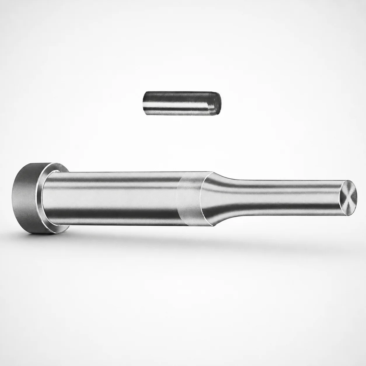
Center Dowel Regular Punches - Metric XNA Coating
Center Dowel Regular Punches - Metric (with XNA coating) provide stable positioning for center alignment in progressive and transfer dies. The XNA surface treatment supports consistent performance under typical punch wear conditions.
- Regular center-dowel punch form for precise die alignment
- XNA coating helps improve wear resistance during operation
- Supports multiple optional tip shapes for different punch point requirements
- Designed for metric press tooling and locating in blanking processes
Specifications
228 configurations available
| Tip shape | D (Shank dia.) (mm) | L1 (Point Length) (mm) | L (Length) (mm) | P Dimension (mm) | W Dimension (mm) | R Dimension (mm) |
|---|---|---|---|---|---|---|
| H | 10 | 19 ~ 25 | 71 ~ 150 | 4 ~ 4.49 | 4 ~ 4.49 | - |
| H | 10 | 19 ~ 25 | 71 ~ 150 | 4 ~ 4.49 | 4.5 ~ 9.95 | - |
| H | 10 | 19 ~ 25 | 71 ~ 150 | 4.5 ~ 9.95 | 4 ~ 4.49 | - |
| H | 10 | 19 ~ 25 | 71 ~ 150 | 4.5 ~ 9.95 | 4.5 ~ 9.95 | - |
| H | 13 | 19 ~ 25 | 71 ~ 150 | 4 ~ 5.99 | 4 ~ 5.99 | - |
| H | 13 | 19 ~ 25 | 71 ~ 150 | 4 ~ 5.99 | 6 ~ 12.95 | - |
| H | 13 | 19 ~ 25 | 71 ~ 150 | 6 ~ 12.95 | 4 ~ 5.99 | - |
| H | 13 | 19 ~ 25 | 71 ~ 150 | 6 ~ 12.95 | 6 ~ 12.95 | - |
| H | 16 | 19 ~ 25 | 71 ~ 150 | 6 ~ 7.19 | 6 ~ 7.19 | - |
| H | 16 | 19 ~ 25 | 71 ~ 150 | 6 ~ 7.19 | 7.2 ~ 15.95 | - |
| H | 16 | 19 ~ 25 | 71 ~ 150 | 7.2 ~ 15.95 | 6 ~ 7.19 | - |
| H | 16 | 19 ~ 25 | 71 ~ 150 | 7.2 ~ 15.95 | 7.2 ~ 15.95 | - |
| H | 20 | 19 ~ 25 | 71 ~ 150 | 6 ~ 7.99 | 6 ~ 7.99 | - |
| H | 20 | 19 ~ 25 | 71 ~ 150 | 6 ~ 7.99 | 8 ~ 19.95 | - |
| H | 20 | 19 ~ 25 | 71 ~ 150 | 8 ~ 19.95 | 6 ~ 7.99 | - |
| H | 20 | 19 ~ 25 | 71 ~ 150 | 8 ~ 19.95 | 8 ~ 19.95 | - |
| H | 25 | 19 ~ 25 | 71 ~ 150 | 6 ~ 8.99 | 6 ~ 8.99 | - |
| H | 25 | 19 ~ 25 | 71 ~ 150 | 6 ~ 8.99 | 9 ~ 24.95 | - |
| H | 25 | 19 ~ 25 | 71 ~ 150 | 9 ~ 24.95 | 6 ~ 8.99 | - |
| H | 25 | 19 ~ 25 | 71 ~ 150 | 9 ~ 24.95 | 9 ~ 24.95 | - |
| H | 32 | 25 ~ 30 | 71 ~ 150 | 7.2 ~ 9.99 | 7.2 ~ 9.99 | - |
| H | 32 | 25 ~ 30 | 71 ~ 150 | 7.2 ~ 9.99 | 10 ~ 31.95 | - |
| H | 32 | 25 ~ 30 | 71 ~ 150 | 10 ~ 31.95 | 7.2 ~ 9.99 | - |
| H | 32 | 25 ~ 30 | 71 ~ 150 | 10 ~ 31.95 | 10 ~ 31.95 | - |
| J | 10 | 19 ~ 25 | 71 ~ 150 | 4 ~ 4.49 | 4 ~ 4.49 | - |
| J | 10 | 19 ~ 25 | 71 ~ 150 | 4 ~ 4.49 | 4.5 ~ 9.95 | - |
| J | 10 | 19 ~ 25 | 71 ~ 150 | 4.5 ~ 9.95 | 4 ~ 4.49 | - |
| J | 10 | 19 ~ 25 | 71 ~ 150 | 4.5 ~ 9.95 | 4.5 ~ 9.95 | - |
| J | 13 | 19 ~ 25 | 71 ~ 150 | 4 ~ 5.99 | 4 ~ 5.99 | - |
| J | 13 | 19 ~ 25 | 71 ~ 150 | 4 ~ 5.99 | 6 ~ 12.95 | - |
| J | 13 | 19 ~ 25 | 71 ~ 150 | 6 ~ 12.95 | 4 ~ 5.99 | - |
| J | 13 | 19 ~ 25 | 71 ~ 150 | 6 ~ 12.95 | 6 ~ 12.95 | - |
| J | 16 | 19 ~ 25 | 71 ~ 150 | 6 ~ 7.19 | 6 ~ 7.19 | - |
| J | 16 | 19 ~ 25 | 71 ~ 150 | 6 ~ 7.19 | 7.2 ~ 15.95 | - |
| J | 16 | 19 ~ 25 | 71 ~ 150 | 7.2 ~ 15.95 | 6 ~ 7.19 | - |
| J | 16 | 19 ~ 25 | 71 ~ 150 | 7.2 ~ 15.95 | 7.2 ~ 15.95 | - |
| J | 20 | 19 ~ 25 | 71 ~ 150 | 6 ~ 7.99 | 6 ~ 7.99 | - |
| J | 20 | 19 ~ 25 | 71 ~ 150 | 6 ~ 7.99 | 8 ~ 19.95 | - |
| J | 20 | 19 ~ 25 | 71 ~ 150 | 8 ~ 19.95 | 6 ~ 7.99 | - |
| J | 20 | 19 ~ 25 | 71 ~ 150 | 8 ~ 19.95 | 8 ~ 19.95 | - |
| J | 25 | 19 ~ 25 | 71 ~ 150 | 6 ~ 8.99 | 6 ~ 8.99 | - |
| J | 25 | 19 ~ 25 | 71 ~ 150 | 6 ~ 8.99 | 9 ~ 24.95 | - |
| J | 25 | 19 ~ 25 | 71 ~ 150 | 9 ~ 24.95 | 6 ~ 8.99 | - |
| J | 25 | 19 ~ 25 | 71 ~ 150 | 9 ~ 24.95 | 9 ~ 24.95 | - |
| J | 32 | 25 ~ 30 | 71 ~ 150 | 7.2 ~ 9.99 | 7.2 ~ 9.99 | - |
| J | 32 | 25 ~ 30 | 71 ~ 150 | 7.2 ~ 9.99 | 10 ~ 31.95 | - |
| J | 32 | 25 ~ 30 | 71 ~ 150 | 10 ~ 31.95 | 7.2 ~ 9.99 | - |
| J | 32 | 25 ~ 30 | 71 ~ 150 | 10 ~ 31.95 | 10 ~ 31.95 | - |
| K | 10 | 19 ~ 25 | 71 ~ 150 | 4 ~ 4.49 | 4 ~ 4.49 | 0.2 ~ 4.975 |
| K | 10 | 19 ~ 25 | 71 ~ 150 | 4 ~ 4.49 | 4.5 ~ 9.95 | 0.2 ~ 4.975 |
Product Guide
Application Scenarios+
This center-dowel punch is used in progressive and transfer press tooling where repeatable part-to-part registration is critical. The locating interface created by the shank and center-dowel hole helps stabilize the center alignment during blanking and piercing, reducing off-center drift across long production runs.
In automotive connector and terminal blanking applications, it supports consistent feed indexing by maintaining punch-to-die positional accuracy. The XNA coating variant is suited for these cycles because it is intended to improve punch surface durability under typical wear conditions.
It is also well matched for electrical housing and bracket fabrication dies, where multiple operations can be stacked. Engineers can select an appropriate tip shape (H, J, K, L, N, O, R, V, X, Y, Z) and point length range to match material thickness and punch point requirements, while the metric sizing aligns with standard die sets.
- Aligns punch/die center for progressive/transfer operations
- XNA coating supports wear performance during blanking cycles
- Tip shape + point length selection enables matching to workpiece needs
Material & Process Details+
The provided specification identifies this item as a center-dowel regular punch with an XNA coating, which is selected to improve operating wear behavior at the sliding/contact surface. However, no specific steel grade, hardness value (HRC), or heat-treatment state (e.g., quench & temper, nitriding) is stated in the available metadata.
In press tooling practice, coating and tip geometry are typically used to balance wear resistance and toughness: harder/coated surfaces can reduce abrasion, while adequate core toughness helps prevent edge chipping under load. For this reason, confirming the underlying base steel specification and hardness is recommended when finalizing a die material-and-load risk assessment.
- XNA coating: intended to enhance wear durability during punch guidance
- No base steel grade/HRC provided in supplied data—verify with your quotation
- Coating selection should be matched to expected cutting force and abrasive conditions
Sizing & Selection Guide+
To select the correct punch, start with the shank diameter D (mm): available sizes are 10, 13, 16, 20, 25, 32. Choose the point length L1 (mm) range based on how deep the cutting/penetration point must extend: 19–25 or 25–30.
The overall fixed length L is specified as 71–150 mm, so ensure your tool stack-up, holder, and guide clearances can accommodate the required L while maintaining stable guidance.
For center registration features, match the guidance geometry inputs to your die hole and clearance requirements using the available variable dimensions:
- P dimension: 4–16 mm
- W dimension: 4–10 mm
- R dimension: select from the provided ranges (e.g., 0.2–4.975 up to 0.2–15.975, depending on configuration)
Fit should be validated with your existing locating hole tolerance stack; because the data lists ranges rather than a single value, select the exact configured dimensions you intend to run in the die set.
Frequently Asked Questions
Which tip shapes are available for the DAYTON center-dowel regular punches with XNA coating?+
How do I choose the shank diameter (D) so the punch centers correctly in my press die?+
What point length (L1) options are available and how do they affect penetration in blanking?+
How should I select R, P, and W dimensions to match my die feature geometry?+
Does the XNA coating replace the need for selecting the correct base steel and heat treatment?+
Related Products

Metric Center Dowel Ejector Punches (SKD11 Equivalent)

Dicoat Treatment SKD11 Steel Center Dowel Ejector Punches - Metric

Center Dowel Ejector Punches - Metric, XCN TiCN Coating

DIN Standard SKD11 Steel Gas Release Single-Stepped Ejector Punches

Center Dowel Ejector Punches with Locating Dowel Hole

DIN Standard TiCN Center Dowel Ejector Punches
Need Custom Specifications?
Our engineering team can help with custom configurations, material selection, and volume pricing.