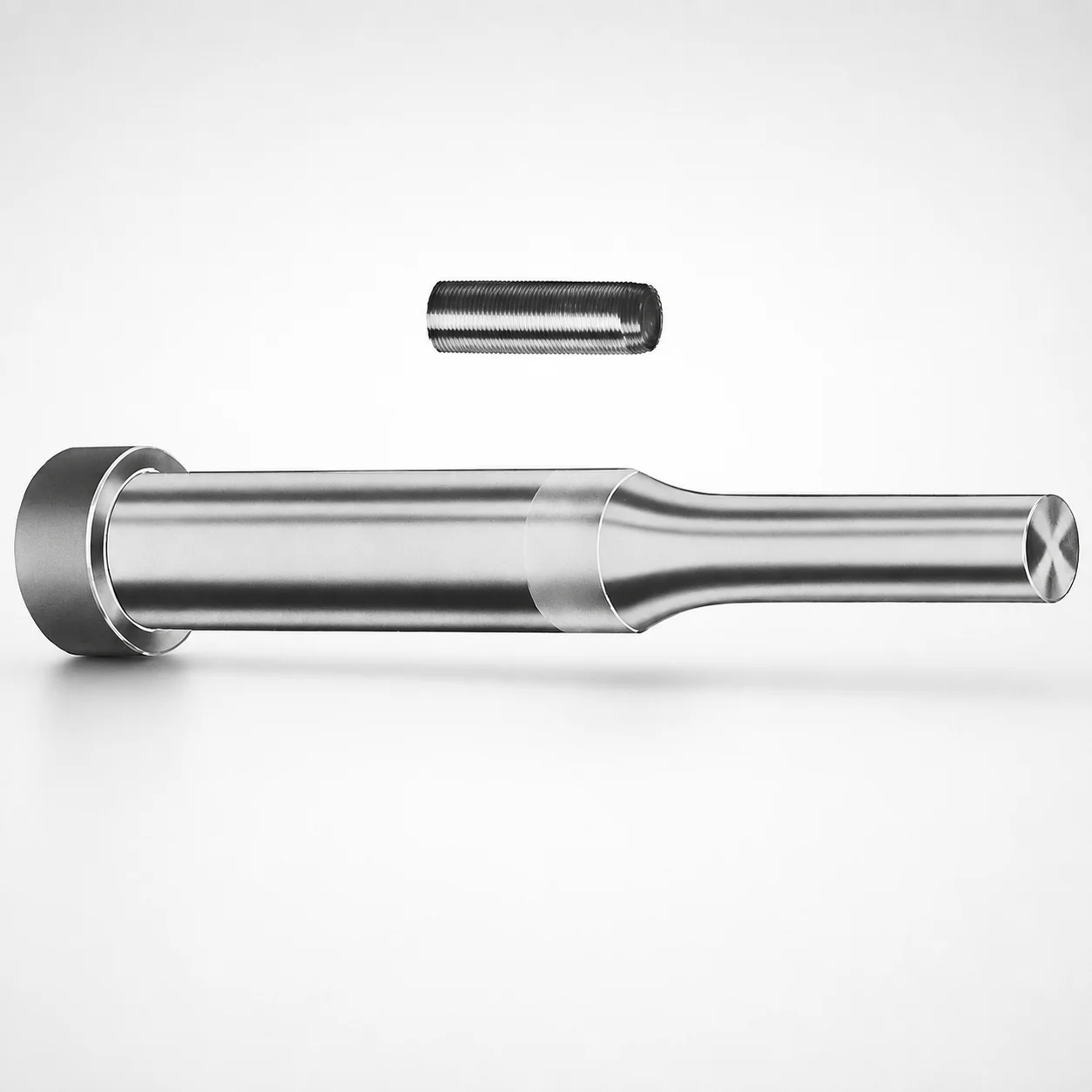
Center Dowel Regular Punches - Metric XN DayTride® Coating
Center Dowel Regular Punches - Metric (XN DayTride® coated) are engineered for precise centering and consistent punch location in progressive and transfer tooling. The standardized geometry supports stable fit during repeated press cycles.
- Regular center dowel punch design improves locating stability in die assemblies
- XN DayTride® coating helps reduce wear for longer service intervals
- Selectable tip shapes (X, R, K, O, H, L, J, N, V, Y, Z) support different spotting needs
- Metric shank sizing options (D 10 to 32 mm) for flexible die layout compatibility
Specifications
228 configurations available
| Tip shape | D (Shank dia.) (mm) | L1 (Point Length) (mm) | L (Length) (mm) | P Dimension (mm) | W Dimension (mm) | R Dimension (mm) |
|---|---|---|---|---|---|---|
| H | 10 | 19 ~ 25 | 71 ~ 150 | 4 ~ 4.49 | 4 ~ 4.49 | - |
| H | 10 | 19 ~ 25 | 71 ~ 150 | 4 ~ 4.49 | 4.5 ~ 9.95 | - |
| H | 10 | 19 ~ 25 | 71 ~ 150 | 4.5 ~ 9.95 | 4 ~ 4.49 | - |
| H | 10 | 19 ~ 25 | 71 ~ 150 | 4.5 ~ 9.95 | 4.5 ~ 9.95 | - |
| H | 13 | 19 ~ 25 | 71 ~ 150 | 4 ~ 5.99 | 4 ~ 5.99 | - |
| H | 13 | 19 ~ 25 | 71 ~ 150 | 4 ~ 5.99 | 6 ~ 12.95 | - |
| H | 13 | 19 ~ 25 | 71 ~ 150 | 6 ~ 12.95 | 4 ~ 5.99 | - |
| H | 13 | 19 ~ 25 | 71 ~ 150 | 6 ~ 12.95 | 6 ~ 12.95 | - |
| H | 16 | 19 ~ 25 | 71 ~ 150 | 6 ~ 7.19 | 6 ~ 7.19 | - |
| H | 16 | 19 ~ 25 | 71 ~ 150 | 6 ~ 7.19 | 7.2 ~ 15.95 | - |
| H | 16 | 19 ~ 25 | 71 ~ 150 | 7.2 ~ 15.95 | 6 ~ 7.19 | - |
| H | 16 | 19 ~ 25 | 71 ~ 150 | 7.2 ~ 15.95 | 7.2 ~ 15.95 | - |
| H | 20 | 19 ~ 25 | 71 ~ 150 | 6 ~ 7.99 | 6 ~ 7.99 | - |
| H | 20 | 19 ~ 25 | 71 ~ 150 | 6 ~ 7.99 | 8 ~ 19.95 | - |
| H | 20 | 19 ~ 25 | 71 ~ 150 | 8 ~ 19.95 | 6 ~ 7.99 | - |
| H | 20 | 19 ~ 25 | 71 ~ 150 | 8 ~ 19.95 | 8 ~ 19.95 | - |
| H | 25 | 19 ~ 25 | 71 ~ 150 | 6 ~ 8.99 | 6 ~ 8.99 | - |
| H | 25 | 19 ~ 25 | 71 ~ 150 | 6 ~ 8.99 | 9 ~ 24.95 | - |
| H | 25 | 19 ~ 25 | 71 ~ 150 | 9 ~ 24.95 | 6 ~ 8.99 | - |
| H | 25 | 19 ~ 25 | 71 ~ 150 | 9 ~ 24.95 | 9 ~ 24.95 | - |
| H | 32 | 25 ~ 30 | 71 ~ 150 | 7.2 ~ 9.99 | 7.2 ~ 9.99 | - |
| H | 32 | 25 ~ 30 | 71 ~ 150 | 7.2 ~ 9.99 | 10 ~ 31.95 | - |
| H | 32 | 25 ~ 30 | 71 ~ 150 | 10 ~ 31.95 | 7.2 ~ 9.99 | - |
| H | 32 | 25 ~ 30 | 71 ~ 150 | 10 ~ 31.95 | 10 ~ 31.95 | - |
| J | 10 | 19 ~ 25 | 71 ~ 150 | 4 ~ 4.49 | 4 ~ 4.49 | - |
| J | 10 | 19 ~ 25 | 71 ~ 150 | 4 ~ 4.49 | 4.5 ~ 9.95 | - |
| J | 10 | 19 ~ 25 | 71 ~ 150 | 4.5 ~ 9.95 | 4 ~ 4.49 | - |
| J | 10 | 19 ~ 25 | 71 ~ 150 | 4.5 ~ 9.95 | 4.5 ~ 9.95 | - |
| J | 13 | 19 ~ 25 | 71 ~ 150 | 4 ~ 5.99 | 4 ~ 5.99 | - |
| J | 13 | 19 ~ 25 | 71 ~ 150 | 4 ~ 5.99 | 6 ~ 12.95 | - |
| J | 13 | 19 ~ 25 | 71 ~ 150 | 6 ~ 12.95 | 4 ~ 5.99 | - |
| J | 13 | 19 ~ 25 | 71 ~ 150 | 6 ~ 12.95 | 6 ~ 12.95 | - |
| J | 16 | 19 ~ 25 | 71 ~ 150 | 6 ~ 7.19 | 6 ~ 7.19 | - |
| J | 16 | 19 ~ 25 | 71 ~ 150 | 6 ~ 7.19 | 7.2 ~ 15.95 | - |
| J | 16 | 19 ~ 25 | 71 ~ 150 | 7.2 ~ 15.95 | 6 ~ 7.19 | - |
| J | 16 | 19 ~ 25 | 71 ~ 150 | 7.2 ~ 15.95 | 7.2 ~ 15.95 | - |
| J | 20 | 19 ~ 25 | 71 ~ 150 | 6 ~ 7.99 | 6 ~ 7.99 | - |
| J | 20 | 19 ~ 25 | 71 ~ 150 | 6 ~ 7.99 | 8 ~ 19.95 | - |
| J | 20 | 19 ~ 25 | 71 ~ 150 | 8 ~ 19.95 | 6 ~ 7.99 | - |
| J | 20 | 19 ~ 25 | 71 ~ 150 | 8 ~ 19.95 | 8 ~ 19.95 | - |
| J | 25 | 19 ~ 25 | 71 ~ 150 | 6 ~ 8.99 | 6 ~ 8.99 | - |
| J | 25 | 19 ~ 25 | 71 ~ 150 | 6 ~ 8.99 | 9 ~ 24.95 | - |
| J | 25 | 19 ~ 25 | 71 ~ 150 | 9 ~ 24.95 | 6 ~ 8.99 | - |
| J | 25 | 19 ~ 25 | 71 ~ 150 | 9 ~ 24.95 | 9 ~ 24.95 | - |
| J | 32 | 25 ~ 30 | 71 ~ 150 | 7.2 ~ 9.99 | 7.2 ~ 9.99 | - |
| J | 32 | 25 ~ 30 | 71 ~ 150 | 7.2 ~ 9.99 | 10 ~ 31.95 | - |
| J | 32 | 25 ~ 30 | 71 ~ 150 | 10 ~ 31.95 | 7.2 ~ 9.99 | - |
| J | 32 | 25 ~ 30 | 71 ~ 150 | 10 ~ 31.95 | 10 ~ 31.95 | - |
| K | 10 | 19 ~ 25 | 71 ~ 150 | 4 ~ 4.49 | 4 ~ 4.49 | 0.2 ~ 4.975 |
| K | 10 | 19 ~ 25 | 71 ~ 150 | 4 ~ 4.49 | 4.5 ~ 9.95 | 0.2 ~ 4.975 |
Product Guide
Application Scenarios+
Center dowel punches are used in injection mold tooling to establish repeatable alignment between die components during each press stroke. This regular center design supports stable punch location in progressive and transfer tooling, where center accuracy and reduced locating wear directly affect part-to-part dimensional consistency.
- Automotive connector and terminal molds: The metric shank options (D 10–32 mm) let you match the dowel interface size to existing die layouts, helping maintain concentric punch/locating alignment under high cycle loads.
- Electronics housings and inserts: Using an XN DayTride® coated punch helps reduce frictional wear at the spotting interface, supporting consistent cavity positioning during repetitive cycling.
- General-purpose multi-cavity housings: Select tip shapes (e.g., X, R, K, O, H, L, J, N, V, Y, Z) to tune spotting behavior for your specific material flow and part features.
The standardized geometry and coating combination make this variant suitable when locating stability and long service intervals are critical.
Material & Process Details+
The provided data specifies a DayTride® (XN) surface coating applied to a regular center dowel punch. While the exact base steel grade and heat treatment state are not listed in the input, this type of coating is selected to improve surface durability and wear performance at the locating interface.
- Wear resistance vs. toughness: Coatings such as DayTride® typically enhance wear resistance and help maintain fit consistency under repeated press cycles; however, very high impact conditions may still require careful alignment control and compatible backing steel selection.
- Heat treatment: The input does not provide a quench-and-temper, pre-hardened, or nitrided specification. Confirm the base material temper and hardness requirements with your Axiom Molds tech team for your press load and spotting depth.
- Coating-related trade-off: Higher surface hardness at the interface generally improves abrasion resistance, supporting longer intervals between regrinds or replacements.
If multiple material/coating options are available for this series, selection should be based on cavity pressure, abrasion level, and required spotting stability.
Sizing & Selection Guide+
To select the correct center dowel regular punch dimensions, match the metric shank and point geometry to your die’s locating and spotting requirements, then verify clearance/fit at assembly.
- Shank diameter (D): Choose from 10, 13, 16, 20, 25, or 32 mm to align with the dowel hole diameter in your die block(s).
- Overall length (L): This series lists L = 71–150 mm (fixed range). Select the length that provides adequate engagement without bottoming in the mating assembly.
- Point length (L1): Available ranges are 19–25 mm and 25–30 mm. Use the shorter range for shallower spotting needs; use the longer range where deeper, more stable initial location is required.
- Tip/geometry parameters: Tip shapes are selectable (H, J, K, L, N, O, R, V, X, Y, Z) and geometry dimensions include P = 4–16 mm, W = 4–10 mm, and R radius options from 0.2 up to 12.475 mm depending on the configuration.
Tolerance/fit: Use these dimensions to select nominal size, then confirm your die hole tolerances and assembly clearance so the coated surface maintains stable location during repeated cycles.
Frequently Asked Questions
Which shank diameter (D) options are available for this center dowel punch series?+
This series provides metric shank diameters D = 10, 13, 16, 20, 25, or 32 mm. Select D to match the dowel hole size in your die base or locating plate. Using the correct nominal diameter helps maintain concentric alignment during progressive or transfer operations.
How do I choose point length (L1) versus overall length (L) when designing die engagement?+
Overall length L is specified as 71–150 mm and is fixed by the selected punch variant. Point length L1 is available as 19–25 mm or 25–30 mm to control spotting depth. Match L1 to how far the punch must extend for stable initial location without excessive penetration.
What tip shapes and radius (R) ranges can be specified for different spotting behavior?+
Tip shapes available include H, J, K, L, N, O, R, V, X, Y, Z. Radius options (R) are configuration-dependent and cover ranges such as 0.2–4.975, 0.2–6.475, 0.2–7.975, 0.2–9.975, 0.2–12.475, with the upper bound varying by selected geometry. Choose the tip shape and R to tune spotting contact and reduce locating wear.
How do P and W dimensions relate to compatibility with die geometry?+
This series lists P = 4–16 mm and W = 4–10 mm as variable geometry dimensions. These affect the point/tip footprint used during initial positioning. Ensure your die pocket or mating interface provides the required clearance for the selected P/W values.
What is the significance of the XN DayTride® coating for locating stability?+
The punch variant includes XN DayTride® coating, intended to help reduce wear at the locating and spotting interface. Reduced wear supports consistent fit and positioning through repeated press cycles. For final selection, confirm that the coating and any required base material hardness align with your expected abrasion, load, and cycle frequency.
Related Products

Metric Center Dowel Ejector Punches (SKD11 Equivalent)

Dicoat Treatment SKD11 Steel Center Dowel Ejector Punches - Metric

Center Dowel Ejector Punches - Metric, XCN TiCN Coating

DIN Standard SKD11 Steel Gas Release Single-Stepped Ejector Punches

Center Dowel Ejector Punches with Locating Dowel Hole

DIN Standard TiCN Center Dowel Ejector Punches
Need Custom Specifications?
Our engineering team can help with custom configurations, material selection, and volume pricing.