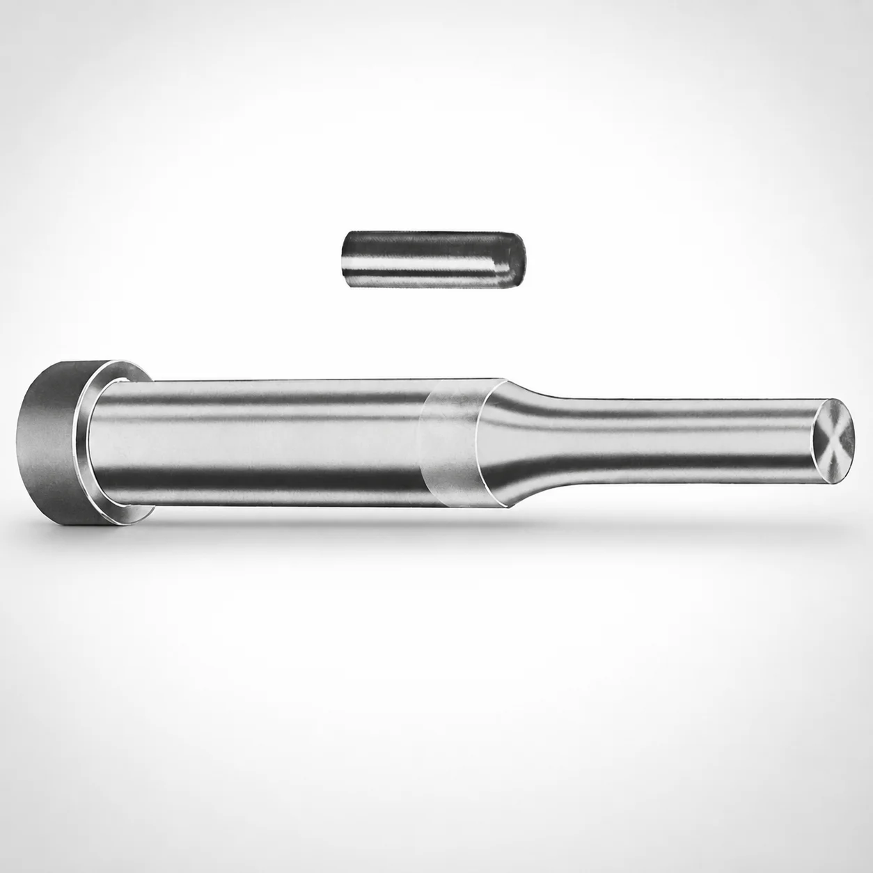
Center Dowel Regular Punches - Metric, XCN Coating
Center Dowel regular punches (Metric) with XCN coating provide stable, repeatable positioning for center locating during punching operations. Built to support smooth press alignment and consistent part geometry across production runs.
- Regular center dowel punch design improves locating stability in punching dies
- XCN coating helps reduce friction and supports wear resistance
- Precision-ground shank geometry supports consistent fit with die sets
- Commonly used in tool and die manufacturing for metric presswork
Specifications
228 configurations available
| Tip shape | D (Shank dia.) (mm) | L1 (Point Length) (mm) | L (Length) (mm) | P Dimension (mm) | W Dimension (mm) | R Dimension (mm) |
|---|---|---|---|---|---|---|
| H | 10 | 19 ~ 25 | 71 ~ 150 | 4 ~ 4.49 | 4 ~ 4.49 | - |
| H | 10 | 19 ~ 25 | 71 ~ 150 | 4 ~ 4.49 | 4.5 ~ 9.95 | - |
| H | 10 | 19 ~ 25 | 71 ~ 150 | 4.5 ~ 9.95 | 4 ~ 4.49 | - |
| H | 10 | 19 ~ 25 | 71 ~ 150 | 4.5 ~ 9.95 | 4.5 ~ 9.95 | - |
| H | 13 | 19 ~ 25 | 71 ~ 150 | 4 ~ 5.99 | 4 ~ 5.99 | - |
| H | 13 | 19 ~ 25 | 71 ~ 150 | 4 ~ 5.99 | 6 ~ 12.95 | - |
| H | 13 | 19 ~ 25 | 71 ~ 150 | 6 ~ 12.95 | 4 ~ 5.99 | - |
| H | 13 | 19 ~ 25 | 71 ~ 150 | 6 ~ 12.95 | 6 ~ 12.95 | - |
| H | 16 | 19 ~ 25 | 71 ~ 150 | 6 ~ 7.19 | 6 ~ 7.19 | - |
| H | 16 | 19 ~ 25 | 71 ~ 150 | 6 ~ 7.19 | 7.2 ~ 15.95 | - |
| H | 16 | 19 ~ 25 | 71 ~ 150 | 7.2 ~ 15.95 | 6 ~ 7.19 | - |
| H | 16 | 19 ~ 25 | 71 ~ 150 | 7.2 ~ 15.95 | 7.2 ~ 15.95 | - |
| H | 20 | 19 ~ 25 | 71 ~ 150 | 6 ~ 7.99 | 6 ~ 7.99 | - |
| H | 20 | 19 ~ 25 | 71 ~ 150 | 6 ~ 7.99 | 8 ~ 19.95 | - |
| H | 20 | 19 ~ 25 | 71 ~ 150 | 8 ~ 19.95 | 6 ~ 7.99 | - |
| H | 20 | 19 ~ 25 | 71 ~ 150 | 8 ~ 19.95 | 8 ~ 19.95 | - |
| H | 25 | 19 ~ 25 | 71 ~ 150 | 6 ~ 8.99 | 6 ~ 8.99 | - |
| H | 25 | 19 ~ 25 | 71 ~ 150 | 6 ~ 8.99 | 9 ~ 24.95 | - |
| H | 25 | 19 ~ 25 | 71 ~ 150 | 9 ~ 24.95 | 6 ~ 8.99 | - |
| H | 25 | 19 ~ 25 | 71 ~ 150 | 9 ~ 24.95 | 9 ~ 24.95 | - |
| H | 32 | 25 ~ 30 | 71 ~ 150 | 7.2 ~ 9.99 | 7.2 ~ 9.99 | - |
| H | 32 | 25 ~ 30 | 71 ~ 150 | 7.2 ~ 9.99 | 10 ~ 31.95 | - |
| H | 32 | 25 ~ 30 | 71 ~ 150 | 10 ~ 31.95 | 7.2 ~ 9.99 | - |
| H | 32 | 25 ~ 30 | 71 ~ 150 | 10 ~ 31.95 | 10 ~ 31.95 | - |
| J | 10 | 19 ~ 25 | 71 ~ 150 | 4 ~ 4.49 | 4 ~ 4.49 | - |
| J | 10 | 19 ~ 25 | 71 ~ 150 | 4 ~ 4.49 | 4.5 ~ 9.95 | - |
| J | 10 | 19 ~ 25 | 71 ~ 150 | 4.5 ~ 9.95 | 4 ~ 4.49 | - |
| J | 10 | 19 ~ 25 | 71 ~ 150 | 4.5 ~ 9.95 | 4.5 ~ 9.95 | - |
| J | 13 | 19 ~ 25 | 71 ~ 150 | 4 ~ 5.99 | 4 ~ 5.99 | - |
| J | 13 | 19 ~ 25 | 71 ~ 150 | 4 ~ 5.99 | 6 ~ 12.95 | - |
| J | 13 | 19 ~ 25 | 71 ~ 150 | 6 ~ 12.95 | 4 ~ 5.99 | - |
| J | 13 | 19 ~ 25 | 71 ~ 150 | 6 ~ 12.95 | 6 ~ 12.95 | - |
| J | 16 | 19 ~ 25 | 71 ~ 150 | 6 ~ 7.19 | 6 ~ 7.19 | - |
| J | 16 | 19 ~ 25 | 71 ~ 150 | 6 ~ 7.19 | 7.2 ~ 15.95 | - |
| J | 16 | 19 ~ 25 | 71 ~ 150 | 7.2 ~ 15.95 | 6 ~ 7.19 | - |
| J | 16 | 19 ~ 25 | 71 ~ 150 | 7.2 ~ 15.95 | 7.2 ~ 15.95 | - |
| J | 20 | 19 ~ 25 | 71 ~ 150 | 6 ~ 7.99 | 6 ~ 7.99 | - |
| J | 20 | 19 ~ 25 | 71 ~ 150 | 6 ~ 7.99 | 8 ~ 19.95 | - |
| J | 20 | 19 ~ 25 | 71 ~ 150 | 8 ~ 19.95 | 6 ~ 7.99 | - |
| J | 20 | 19 ~ 25 | 71 ~ 150 | 8 ~ 19.95 | 8 ~ 19.95 | - |
| J | 25 | 19 ~ 25 | 71 ~ 150 | 6 ~ 8.99 | 6 ~ 8.99 | - |
| J | 25 | 19 ~ 25 | 71 ~ 150 | 6 ~ 8.99 | 9 ~ 24.95 | - |
| J | 25 | 19 ~ 25 | 71 ~ 150 | 9 ~ 24.95 | 6 ~ 8.99 | - |
| J | 25 | 19 ~ 25 | 71 ~ 150 | 9 ~ 24.95 | 9 ~ 24.95 | - |
| J | 32 | 25 ~ 30 | 71 ~ 150 | 7.2 ~ 9.99 | 7.2 ~ 9.99 | - |
| J | 32 | 25 ~ 30 | 71 ~ 150 | 7.2 ~ 9.99 | 10 ~ 31.95 | - |
| J | 32 | 25 ~ 30 | 71 ~ 150 | 10 ~ 31.95 | 7.2 ~ 9.99 | - |
| J | 32 | 25 ~ 30 | 71 ~ 150 | 10 ~ 31.95 | 10 ~ 31.95 | - |
| K | 10 | 19 ~ 25 | 71 ~ 150 | 4 ~ 4.49 | 4 ~ 4.49 | 0.2 ~ 4.975 |
| K | 10 | 19 ~ 25 | 71 ~ 150 | 4 ~ 4.49 | 4.5 ~ 9.95 | 0.2 ~ 4.975 |
Product Guide
Application Scenarios+
Center dowel regular punches with a metric XCN coating are used in progressive and compound punching dies to establish repeatable center location between tool components. They are especially useful where consistent hole position directly affects downstream forming, trimming, or assembly.
- Automotive and appliance sheet-metal punching: Use these punches to stabilize press alignment and maintain part-to-part geometry across high-volume runs, benefiting from the regular center dowel layout and the XCN surface to manage friction and wear at the locating interface.
- Electronics and small bracket dies: The defined metric shank diameters support precise die-set mating, helping reduce locating drift when punching small features where cumulative tolerance stack-up is critical.
- Toolroom-built tooling for job shops: The variety of tip shapes (H, J, K, L, N, O, R, V, X, Y, Z) allows engineers to match the punch end geometry to the die wear strategy and contact conditions.
Material & Process Details+
The provided specification set does not include a specific steel grade or heat treatment condition, so material selection should be confirmed with the toolmaker’s die steel standard for punching applications. In practice, center locating punches are commonly made from hardened tool steels to balance wear resistance at the locating contact with toughness against edge chipping from press impact.
- XCN coating: The XCN coating is used to improve the locating interface by reducing friction and supporting wear resistance during repeated alignment cycles.
- Heat treatment approach (verification recommended): Select a quenched & tempered or nitrided condition if your application emphasizes sliding wear and dimensional stability under load.
- Trade-off guidance: Higher surface hardness typically increases wear resistance but can reduce shock toughness; tune hardness to match press tonnage and strip thickness.
Sizing & Selection Guide+
Choose dimensions to match your die set’s locating requirements so the punch centers the operation reliably through the full stroke. This series uses metric shank diameter (D) options of 10, 13, 16, 20, 25, and 32 mm, and a fixed overall length (L) range of 71 to 150 mm.
- Shank diameter (D): Select D to fit the corresponding dowel-hole/bushing bore used in your punch guide or die set.
- Point length (L1): Use 19–25 mm or 25–30 mm based on the required engagement depth for stable center location without bottoming.
- Tip shape and end geometry: Pick from H, J, K, L, N, O, R, V, X, Y, Z to suit the contact profile and wear behavior in your tooling.
- Other critical geometry: Match P (4–16 mm), W (4–10 mm), and R (0.2–4.975, 0.2–6.475, 0.2–7.975, 0.2–9.975, 0.2–12.475, 0.2–15.975) to the mating feature radii and clearance design.
Confirm tolerances at the interface with your press-fit or clearance specification to prevent locating drift or binding during repeated cycles.
Frequently Asked Questions
Which metric shank diameter (D) options are available for the center locating punch, and how do I select the right one for my die-set holes?+
This series provides D (shank dia.) options of 10, 13, 16, 20, 25, and 32 mm. Select the diameter that matches (or is engineered to fit) your die-set locating bore for the intended clearance/fit method. Verify engagement depth using L1 so the punch properly centers without excessive bottoming or tool interference.
How should I choose the point length (L1) and overall length (L) to ensure stable center location through punching strokes?+
The available L1 (point length) options are 19–25 mm and 25–30 mm, while L is fixed as a range of 71–150 mm depending on the selected configuration. Use L1 to control locating engagement in the mating feature, and use the available L range to match your die block thickness stack-up. If your tooling has large variation in wear or spacer heights, confirm that the punch remains properly supported through the full stroke.
What do the tip shapes (H, J, K, L, N, O, R, V, X, Y, Z) affect in punching die performance?+
Tip shapes determine the punch end contact profile used for center locating and guiding behavior in the die. Selecting a tip shape affects how the punch transitions into the mating feature and how quickly wear develops at the interface. Pair the chosen tip profile with your specified P, W, and R dimensions to maintain designed clearances and prevent misalignment under load.
How does the XCN coating influence wear and friction in center locating punches for production runs?+
The XCN coating is specified to improve the locating interface by reducing friction and supporting wear resistance. This helps maintain stable repeatable positioning during repeated punch cycles, particularly where there is sliding or rubbing at the guide and locating surfaces. For severe duty cycles, validate coating performance alongside the required engagement depth and surface geometry to prevent binding.
Which geometric parameters besides D and L are critical when integrating this punch into a die design?+
Besides D and L, the configuration includes P (4–16 mm), W (4–10 mm), and R radius options (0.2–4.975 up to 0.2–15.975 depending on the configuration family). These parameters must match the mating feature geometry in the die set to achieve the intended fit and contact. Ensure your design tolerance strategy accommodates the combined effects of wear and repeated press loading.
Related Products

Metric Center Dowel Ejector Punches (SKD11 Equivalent)

Dicoat Treatment SKD11 Steel Center Dowel Ejector Punches - Metric

Center Dowel Ejector Punches - Metric, XCN TiCN Coating

DIN Standard SKD11 Steel Gas Release Single-Stepped Ejector Punches

Center Dowel Ejector Punches with Locating Dowel Hole

DIN Standard TiCN Center Dowel Ejector Punches
Need Custom Specifications?
Our engineering team can help with custom configurations, material selection, and volume pricing.