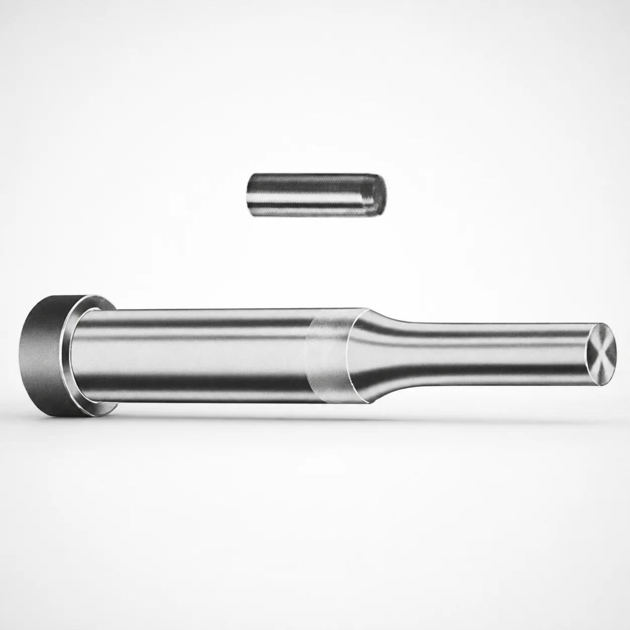
Center Dowel Regular Punches - Metric (M2 Steel)
Center Dowel Regular Punches - Metric (M2 steel) are designed for accurate positioning and stable punch alignment in progressive forming dies. The regular center-dowel style supports repeatable part registration during high-cycle production.
- Center dowel punch geometry improves locating stability in die sets
- M2 steel provides wear resistance for long service intervals
- Optimized point options help match different die and workpiece requirements
- Metric punches used in toolmaking and progressive die applications
Specifications
456 configurations available
| Tip shape | Material | D (Shank dia.) (mm) | L1 (Point Length) (mm) | L (Length) (mm) | P Dimension (mm) | W Dimension (mm) | R Dimension (mm) |
|---|---|---|---|---|---|---|---|
| H | M2 | 10 | 19 ~ 25 | 71 ~ 150 | 4 ~ 4.49 | 4 ~ 4.49 | - |
| H | M2 | 10 | 19 ~ 25 | 71 ~ 150 | 4 ~ 4.49 | 4.5 ~ 9.95 | - |
| H | M2 | 10 | 19 ~ 25 | 71 ~ 150 | 4.5 ~ 9.95 | 4 ~ 4.49 | - |
| H | M2 | 10 | 19 ~ 25 | 71 ~ 150 | 4.5 ~ 9.95 | 4.5 ~ 9.95 | - |
| H | A2 | 10 | 19 ~ 25 | 71 ~ 150 | 4 ~ 4.49 | 4 ~ 4.49 | - |
| H | A2 | 10 | 19 ~ 25 | 71 ~ 150 | 4 ~ 4.49 | 4.5 ~ 9.95 | - |
| H | A2 | 10 | 19 ~ 25 | 71 ~ 150 | 4.5 ~ 9.95 | 4 ~ 4.49 | - |
| H | A2 | 10 | 19 ~ 25 | 71 ~ 150 | 4.5 ~ 9.95 | 4.5 ~ 9.95 | - |
| H | M2 | 13 | 19 ~ 25 | 71 ~ 150 | 4 ~ 5.99 | 4 ~ 5.99 | - |
| H | M2 | 13 | 19 ~ 25 | 71 ~ 150 | 4 ~ 5.99 | 6 ~ 12.95 | - |
| H | M2 | 13 | 19 ~ 25 | 71 ~ 150 | 6 ~ 12.95 | 4 ~ 5.99 | - |
| H | M2 | 13 | 19 ~ 25 | 71 ~ 150 | 6 ~ 12.95 | 6 ~ 12.95 | - |
| H | A2 | 13 | 19 ~ 25 | 71 ~ 150 | 4 ~ 5.99 | 4 ~ 5.99 | - |
| H | A2 | 13 | 19 ~ 25 | 71 ~ 150 | 4 ~ 5.99 | 6 ~ 12.95 | - |
| H | A2 | 13 | 19 ~ 25 | 71 ~ 150 | 6 ~ 12.95 | 4 ~ 5.99 | - |
| H | A2 | 13 | 19 ~ 25 | 71 ~ 150 | 6 ~ 12.95 | 6 ~ 12.95 | - |
| H | M2 | 16 | 19 ~ 25 | 71 ~ 150 | 6 ~ 7.19 | 6 ~ 7.19 | - |
| H | M2 | 16 | 19 ~ 25 | 71 ~ 150 | 6 ~ 7.19 | 7.2 ~ 15.95 | - |
| H | M2 | 16 | 19 ~ 25 | 71 ~ 150 | 7.2 ~ 15.95 | 6 ~ 7.19 | - |
| H | M2 | 16 | 19 ~ 25 | 71 ~ 150 | 7.2 ~ 15.95 | 7.2 ~ 15.95 | - |
| H | A2 | 16 | 19 ~ 25 | 71 ~ 150 | 6 ~ 7.19 | 6 ~ 7.19 | - |
| H | A2 | 16 | 19 ~ 25 | 71 ~ 150 | 6 ~ 7.19 | 7.2 ~ 15.95 | - |
| H | A2 | 16 | 19 ~ 25 | 71 ~ 150 | 7.2 ~ 15.95 | 6 ~ 7.19 | - |
| H | A2 | 16 | 19 ~ 25 | 71 ~ 150 | 7.2 ~ 15.95 | 7.2 ~ 15.95 | - |
| H | M2 | 20 | 19 ~ 25 | 71 ~ 150 | 6 ~ 7.99 | 6 ~ 7.99 | - |
| H | M2 | 20 | 19 ~ 25 | 71 ~ 150 | 6 ~ 7.99 | 8 ~ 19.95 | - |
| H | M2 | 20 | 19 ~ 25 | 71 ~ 150 | 8 ~ 19.95 | 6 ~ 7.99 | - |
| H | M2 | 20 | 19 ~ 25 | 71 ~ 150 | 8 ~ 19.95 | 8 ~ 19.95 | - |
| H | A2 | 20 | 19 ~ 25 | 71 ~ 150 | 6 ~ 7.99 | 6 ~ 7.99 | - |
| H | A2 | 20 | 19 ~ 25 | 71 ~ 150 | 6 ~ 7.99 | 8 ~ 19.95 | - |
| H | A2 | 20 | 19 ~ 25 | 71 ~ 150 | 8 ~ 19.95 | 6 ~ 7.99 | - |
| H | A2 | 20 | 19 ~ 25 | 71 ~ 150 | 8 ~ 19.95 | 8 ~ 19.95 | - |
| H | M2 | 25 | 19 ~ 25 | 71 ~ 150 | 6 ~ 8.99 | 6 ~ 8.99 | - |
| H | M2 | 25 | 19 ~ 25 | 71 ~ 150 | 6 ~ 8.99 | 9 ~ 24.95 | - |
| H | M2 | 25 | 19 ~ 25 | 71 ~ 150 | 9 ~ 24.95 | 6 ~ 8.99 | - |
| H | M2 | 25 | 19 ~ 25 | 71 ~ 150 | 9 ~ 24.95 | 9 ~ 24.95 | - |
| H | A2 | 25 | 19 ~ 25 | 71 ~ 150 | 6 ~ 8.99 | 6 ~ 8.99 | - |
| H | A2 | 25 | 19 ~ 25 | 71 ~ 150 | 6 ~ 8.99 | 9 ~ 24.95 | - |
| H | A2 | 25 | 19 ~ 25 | 71 ~ 150 | 9 ~ 24.95 | 6 ~ 8.99 | - |
| H | A2 | 25 | 19 ~ 25 | 71 ~ 150 | 9 ~ 24.95 | 9 ~ 24.95 | - |
| H | M2 | 32 | 25 ~ 30 | 71 ~ 150 | 7.2 ~ 9.99 | 7.2 ~ 9.99 | - |
| H | M2 | 32 | 25 ~ 30 | 71 ~ 150 | 7.2 ~ 9.99 | 10 ~ 31.95 | - |
| H | M2 | 32 | 25 ~ 30 | 71 ~ 150 | 10 ~ 31.95 | 7.2 ~ 9.99 | - |
| H | M2 | 32 | 25 ~ 30 | 71 ~ 150 | 10 ~ 31.95 | 10 ~ 31.95 | - |
| H | A2 | 32 | 25 ~ 30 | 71 ~ 150 | 7.2 ~ 9.99 | 7.2 ~ 9.99 | - |
| H | A2 | 32 | 25 ~ 30 | 71 ~ 150 | 7.2 ~ 9.99 | 10 ~ 31.95 | - |
| H | A2 | 32 | 25 ~ 30 | 71 ~ 150 | 10 ~ 31.95 | 7.2 ~ 9.99 | - |
| H | A2 | 32 | 25 ~ 30 | 71 ~ 150 | 10 ~ 31.95 | 10 ~ 31.95 | - |
| J | M2 | 10 | 19 ~ 25 | 71 ~ 150 | 4 ~ 4.49 | 4 ~ 4.49 | - |
| J | M2 | 10 | 19 ~ 25 | 71 ~ 150 | 4 ~ 4.49 | 4.5 ~ 9.95 | - |
Product Guide
Application Scenarios+
Center dowel punches like this are used in progressive die sets where each station relies on stable, repeatable part registration. They help maintain punch-to-die alignment so strip-fed forming operations stay on tolerance across high cycle counts.
- Automotive connector and terminal progressive dies: The center-dowel locating helps prevent gradual misalignment between feed steps, supporting consistent forming geometry at the tips.
- Sheet-metal bracket and housing stamping: The regular center-dowel style improves locating stability, which is critical when multiple stations shear, pierce, and form in sequence.
- Small precision metal components: Tip shape options (H, J, K, L, N, O, R, V, X, Y, Z) allow you to tune the forming alignment for different material thicknesses and feature profiles.
The supplied M2 steel variant is suited to these applications because it is selected for wear resistance, helping maintain tip geometry and alignment over longer service intervals.
Material & Process Details+
This punch is offered in M2 steel (also available in A2 per the provided options). In common die practice, M2 corresponds to an AISI M2-type high-speed steel family, providing strong wear resistance and good performance where punch tips see repeated contact and abrasive debris.
- Hardness / performance balance: High-speed tool steels like M2 are typically heat treated to achieve high hardness for wear resistance; however, increased hardness can reduce edge toughness under heavy shock loading.
- Heat treatment state: These center punches are manufactured to a hardened tool-steel condition suitable for precision forming/blanking. Specific HRC values and exact heat-treatment steps are not provided in the data.
- Material comparison: M2 is generally selected for longer wear life, while A2 is often chosen when a different toughness/wear balance is preferred for the tool duty cycle.
Select the material based on expected abrasion, cutting load, and the severity of misalignment shocks in the progressive die.
Sizing & Selection Guide+
Use the shank and working geometry to match your die set. First, choose D (shank diameter) from the available sizes: 10, 13, 16, 20, 25, or 32 mm, which must fit the corresponding guide/bushing and mating die opening design in your turret/progressive tool.
- Overall length L is fixed at 71 to 150 mm depending on the selected part; ensure the length clears neighbors and supports correct protrusion through the die stack.
- Point length L1 is selectable in ranges: 19 to 25 mm or 25 to 30 mm—use this to set the effective locating/penetration length for your station.
- Tip geometry is selected by tip shape (H, J, K, L, N, O, R, V, X, Y, Z), and the tip profile parameters P (4 to 16 mm), W (4 to 10 mm), and R (0.2 to 4.975 / 6.475 / 7.975 / 9.975 / 12.475 / 15.975) to match the feature you are forming or piercing.
Because specific tolerances are not listed, rely on your die designer’s standard fit rules for dowel/punch guidance, and confirm clearances with the die bushing/receiver dimensions in your CAD stack-up.
Frequently Asked Questions
Which shank diameter D options are compatible with my die set guide openings?+
This series is available with D (shank dia.) values of 10, 13, 16, 20, 25, and 32 mm. Select the D size that matches the guide system (bushings/holes) in your progressive die so the punch can translate without binding.
How do I choose the correct point length L1 for progressive station registration?+
L1 (Point Length) is offered in 19–25 mm and 25–30 mm ranges. Pick the L1 that provides the required effective locating/protrusion at the working face while maintaining safe clearance through the die stack.
What tip shape and radius R should I select for different forming/blanking profiles?+
Tip shape can be selected from H, J, K, L, N, O, R, V, X, Y, Z. The tip radius R is available in multiple ranges (e.g., 0.2–4.975, 0.2–6.475, up to 0.2–15.975), and P/W dimensions vary as well (P: 4–16 mm, W: 4–10 mm).
Is M2 steel or A2 steel better for long-run wear in progressive dies?+
The product is offered in M2 and A2. M2 is generally selected when maximizing wear resistance and preserving tip geometry is a priority over long production runs; A2 can be chosen when your duty cycle emphasizes a different wear/toughness balance.
The catalog lists fixed overall length L—how do I verify stack clearance?+
Overall L is specified as 71–150 mm (fixed per selected configuration). Verify that the chosen L does not interfere with adjacent die components and that the selected L1 achieves the desired functional projection in your station without bottoming.
Related Products

Metric Center Dowel Ejector Punches (SKD11 Equivalent)

Dicoat Treatment SKD11 Steel Center Dowel Ejector Punches - Metric

Center Dowel Ejector Punches - Metric, XCN TiCN Coating

DIN Standard SKD11 Steel Gas Release Single-Stepped Ejector Punches

Center Dowel Ejector Punches with Locating Dowel Hole

DIN Standard TiCN Center Dowel Ejector Punches
Need Custom Specifications?
Our engineering team can help with custom configurations, material selection, and volume pricing.