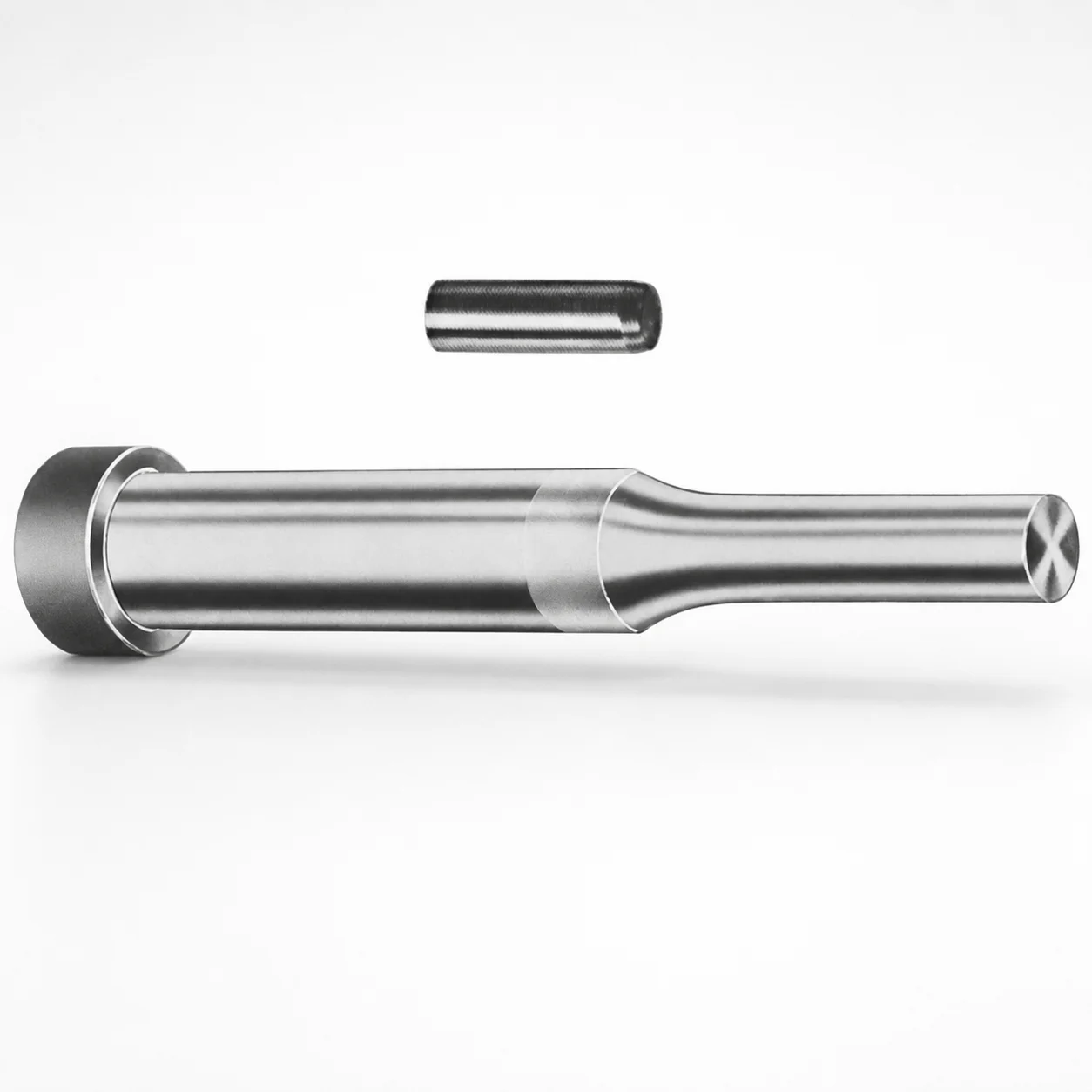
Center Dowel Regular Punches - Metric, XNT DayTiN® Coating
Center Dowel regular punches - metric (DAYTON XNT DayTiN® coating) are designed for accurate positioning and stable ejection performance in punch and die builds. The coating supports improved surface durability where repeated cycling is required.
- Regular center punch form supports consistent locating during press operation
- XNT DayTiN® coating helps resist wear and maintain dimensional stability
- Coordinated point geometry for reliable part centering across repeat runs
- Suitable for metric tool and die assemblies requiring long-cycle accuracy
Specifications
228 configurations available
| Tip shape | D (Shank dia.) (mm) | L1 (Point Length) (mm) | L (Length) (mm) | P Dimension (mm) | W Dimension (mm) | R Dimension (mm) |
|---|---|---|---|---|---|---|
| H | 10 | 19 ~ 25 | 71 ~ 150 | 4 ~ 4.49 | 4 ~ 4.49 | - |
| H | 10 | 19 ~ 25 | 71 ~ 150 | 4 ~ 4.49 | 4.5 ~ 9.95 | - |
| H | 10 | 19 ~ 25 | 71 ~ 150 | 4.5 ~ 9.95 | 4 ~ 4.49 | - |
| H | 10 | 19 ~ 25 | 71 ~ 150 | 4.5 ~ 9.95 | 4.5 ~ 9.95 | - |
| H | 13 | 19 ~ 25 | 71 ~ 150 | 4 ~ 5.99 | 4 ~ 5.99 | - |
| H | 13 | 19 ~ 25 | 71 ~ 150 | 4 ~ 5.99 | 6 ~ 12.95 | - |
| H | 13 | 19 ~ 25 | 71 ~ 150 | 6 ~ 12.95 | 4 ~ 5.99 | - |
| H | 13 | 19 ~ 25 | 71 ~ 150 | 6 ~ 12.95 | 6 ~ 12.95 | - |
| H | 16 | 19 ~ 25 | 71 ~ 150 | 6 ~ 7.19 | 6 ~ 7.19 | - |
| H | 16 | 19 ~ 25 | 71 ~ 150 | 6 ~ 7.19 | 7.2 ~ 15.95 | - |
| H | 16 | 19 ~ 25 | 71 ~ 150 | 7.2 ~ 15.95 | 6 ~ 7.19 | - |
| H | 16 | 19 ~ 25 | 71 ~ 150 | 7.2 ~ 15.95 | 7.2 ~ 15.95 | - |
| H | 20 | 19 ~ 25 | 71 ~ 150 | 6 ~ 7.99 | 6 ~ 7.99 | - |
| H | 20 | 19 ~ 25 | 71 ~ 150 | 6 ~ 7.99 | 8 ~ 19.95 | - |
| H | 20 | 19 ~ 25 | 71 ~ 150 | 8 ~ 19.95 | 6 ~ 7.99 | - |
| H | 20 | 19 ~ 25 | 71 ~ 150 | 8 ~ 19.95 | 8 ~ 19.95 | - |
| H | 25 | 19 ~ 25 | 71 ~ 150 | 6 ~ 8.99 | 6 ~ 8.99 | - |
| H | 25 | 19 ~ 25 | 71 ~ 150 | 6 ~ 8.99 | 9 ~ 24.95 | - |
| H | 25 | 19 ~ 25 | 71 ~ 150 | 9 ~ 24.95 | 6 ~ 8.99 | - |
| H | 25 | 19 ~ 25 | 71 ~ 150 | 9 ~ 24.95 | 9 ~ 24.95 | - |
| H | 32 | 25 ~ 30 | 71 ~ 150 | 7.2 ~ 9.99 | 7.2 ~ 9.99 | - |
| H | 32 | 25 ~ 30 | 71 ~ 150 | 7.2 ~ 9.99 | 10 ~ 31.95 | - |
| H | 32 | 25 ~ 30 | 71 ~ 150 | 10 ~ 31.95 | 7.2 ~ 9.99 | - |
| H | 32 | 25 ~ 30 | 71 ~ 150 | 10 ~ 31.95 | 10 ~ 31.95 | - |
| J | 10 | 19 ~ 25 | 71 ~ 150 | 4 ~ 4.49 | 4 ~ 4.49 | - |
| J | 10 | 19 ~ 25 | 71 ~ 150 | 4 ~ 4.49 | 4.5 ~ 9.95 | - |
| J | 10 | 19 ~ 25 | 71 ~ 150 | 4.5 ~ 9.95 | 4 ~ 4.49 | - |
| J | 10 | 19 ~ 25 | 71 ~ 150 | 4.5 ~ 9.95 | 4.5 ~ 9.95 | - |
| J | 13 | 19 ~ 25 | 71 ~ 150 | 4 ~ 5.99 | 4 ~ 5.99 | - |
| J | 13 | 19 ~ 25 | 71 ~ 150 | 4 ~ 5.99 | 6 ~ 12.95 | - |
| J | 13 | 19 ~ 25 | 71 ~ 150 | 6 ~ 12.95 | 4 ~ 5.99 | - |
| J | 13 | 19 ~ 25 | 71 ~ 150 | 6 ~ 12.95 | 6 ~ 12.95 | - |
| J | 16 | 19 ~ 25 | 71 ~ 150 | 6 ~ 7.19 | 6 ~ 7.19 | - |
| J | 16 | 19 ~ 25 | 71 ~ 150 | 6 ~ 7.19 | 7.2 ~ 15.95 | - |
| J | 16 | 19 ~ 25 | 71 ~ 150 | 7.2 ~ 15.95 | 6 ~ 7.19 | - |
| J | 16 | 19 ~ 25 | 71 ~ 150 | 7.2 ~ 15.95 | 7.2 ~ 15.95 | - |
| J | 20 | 19 ~ 25 | 71 ~ 150 | 6 ~ 7.99 | 6 ~ 7.99 | - |
| J | 20 | 19 ~ 25 | 71 ~ 150 | 6 ~ 7.99 | 8 ~ 19.95 | - |
| J | 20 | 19 ~ 25 | 71 ~ 150 | 8 ~ 19.95 | 6 ~ 7.99 | - |
| J | 20 | 19 ~ 25 | 71 ~ 150 | 8 ~ 19.95 | 8 ~ 19.95 | - |
| J | 25 | 19 ~ 25 | 71 ~ 150 | 6 ~ 8.99 | 6 ~ 8.99 | - |
| J | 25 | 19 ~ 25 | 71 ~ 150 | 6 ~ 8.99 | 9 ~ 24.95 | - |
| J | 25 | 19 ~ 25 | 71 ~ 150 | 9 ~ 24.95 | 6 ~ 8.99 | - |
| J | 25 | 19 ~ 25 | 71 ~ 150 | 9 ~ 24.95 | 9 ~ 24.95 | - |
| J | 32 | 25 ~ 30 | 71 ~ 150 | 7.2 ~ 9.99 | 7.2 ~ 9.99 | - |
| J | 32 | 25 ~ 30 | 71 ~ 150 | 7.2 ~ 9.99 | 10 ~ 31.95 | - |
| J | 32 | 25 ~ 30 | 71 ~ 150 | 10 ~ 31.95 | 7.2 ~ 9.99 | - |
| J | 32 | 25 ~ 30 | 71 ~ 150 | 10 ~ 31.95 | 10 ~ 31.95 | - |
| K | 10 | 19 ~ 25 | 71 ~ 150 | 4 ~ 4.49 | 4 ~ 4.49 | 0.2 ~ 4.975 |
| K | 10 | 19 ~ 25 | 71 ~ 150 | 4 ~ 4.49 | 4.5 ~ 9.95 | 0.2 ~ 4.975 |
Product Guide
Application Scenarios+
This metric center dowel punch set is used in injection tooling where repeatable part positioning and controlled ejection are critical. It is commonly specified in tooling for automotive connector housings and other high-cycle components, where stable center-to-cavity alignment helps reduce mis-trims and improves cycle-to-cycle consistency.
The regular punch geometry supports consistent locating during press operations, while the XNT DayTiN® coating improves surface durability in areas exposed to abrasion from repeated contact. For appliance and electronics enclosures, the robust interface helps maintain dimensional stability across long production runs, supporting reliable part centering.
Engineers also select these punches for general tool-and-die applications with metric layouts where a coordinated tip and shank arrangement reduces variation in the initial contact phase of ejection. The available tip shapes (H, J, K, L, N, O, R, V, X, Y, Z) allow matching the locating behavior to part geometry and process requirements.
Material & Process Details+
These center dowel regular punches are supplied with an XNT DayTiN® coating, engineered to enhance wear resistance at the working surface. While the provided specifications focus on geometry and coating, the key functional intent of the coating is to resist abrasion and help maintain dimensional stability under repeated cycling.
- Wear resistance: Improved surface durability for long-cycle press and ejection conditions where contact wear is expected.
- Toughness trade-off: As with many hard surface coatings, performance is optimized for sliding/abrasion resistance; designers should avoid designs that concentrate high impact loads on the coated region.
- Heat treatment state: The coating is the stated performance material feature; no specific base steel grade or heat treatment (e.g., quenched & tempered, nitrided) is listed in the provided data.
If you require a specific base steel grade or hardness target (HRC) for your tool life model, confirm the underlying material and treatment with Axiom Molds using your preferred D and L selections.
Sizing & Selection Guide+
Select the correct punch size by matching the shank diameter (D), point length (L1), and overall length (L) to your die block and stripper/ejector layout. The shank diameter is available in 10, 13, 16, 20, 25, 32 mm, and should be chosen to match the hole size in the opposing plate while maintaining proper guidance and clearance.
Overall length is fixed at L = 71 to 150 mm, so choose the value that provides sufficient engagement while avoiding bottoming in your assembly. Point length is variable at L1 = 19 to 25 mm or 25 to 30 mm, which determines how far the locating point enters during initial ejection.
- Adjust tip geometry: Choose the tip shape (H, J, K, L, N, O, R, V, X, Y, Z) and the P and W dimensions (P = 4 to 16 mm, W = 4 to 10 mm) to suit the center feature of your part and the corresponding recess/locating pocket.
- Radius (R) tuning: R is available across multiple ranges (e.g., 0.2 to 4.975 up to 0.2 to 15.975 mm); use the largest radius that still clears your cavity geometry to reduce stress concentration at first contact.
Tolerance and fit guidance is not provided in the dataset; verify your punch-to-dowel hole clearance requirements with your standard and confirm any tolerance band for the selected D.
Frequently Asked Questions
Which shank diameter (D) options are available for the metric center dowel regular punches?+
The available D (shank diameter) options are 10, 13, 16, 20, 25, and 32 mm. Select D to match the die plate or supporting component hole sizing used for guidance in your metric tool layout.
How do I choose point length (L1) for correct locating during ejection?+
Point length L1 is offered in 19–25 mm and 25–30 mm ranges. Use the shorter L1 when you need reduced penetration for parts with shallow locating features, and the longer L1 when deeper initial centering is required.
What coating feature is specified and what problem does it address in high-cycle punch/die operations?+
The punches are specified with XNT DayTiN® coating. Its stated purpose is improved surface durability to help resist wear and maintain dimensional stability during repeated cycling where locating and ejection surfaces contact repeatedly.
Can I match the locating tip geometry using the provided tip shape and radii ranges?+
Yes. Tip shapes are available as H, J, K, L, N, O, R, V, X, Y, Z, and radius R is offered in multiple ranges starting at 0.2 mm up to 15.975 mm, depending on the configuration.
What should I verify when selecting overall punch length (L) for tool assembly fit?+
Overall L is fixed as 71–150 mm, so you must choose the length that provides adequate engagement without bottoming in your ejector/stripper stack-up. Confirm that the chosen L works with your die block thickness and the mounting distance to the locating pocket.
Related Products

Metric Center Dowel Ejector Punches (SKD11 Equivalent)

Dicoat Treatment SKD11 Steel Center Dowel Ejector Punches - Metric

Center Dowel Ejector Punches - Metric, XCN TiCN Coating

DIN Standard SKD11 Steel Gas Release Single-Stepped Ejector Punches

Center Dowel Ejector Punches with Locating Dowel Hole

DIN Standard TiCN Center Dowel Ejector Punches
Need Custom Specifications?
Our engineering team can help with custom configurations, material selection, and volume pricing.