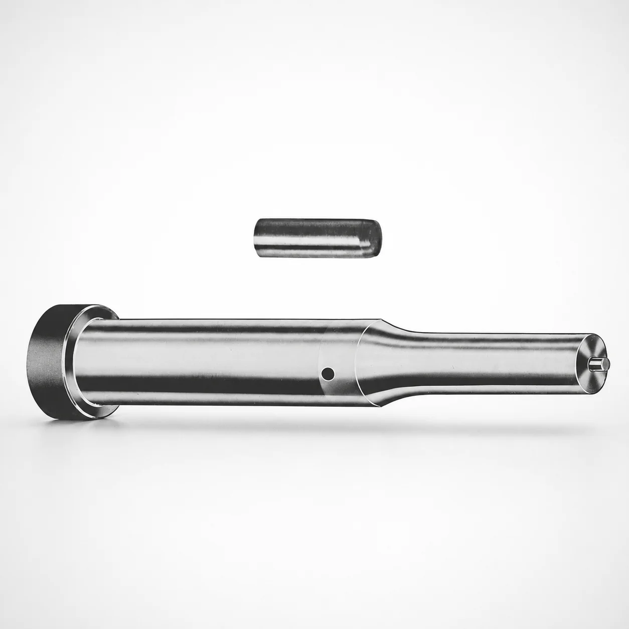
Center Dowel Ejector Punches - Metric XNAP Coating
Center Dowel Ejector Punches - Metric (DAYTON XNAP coating) are designed to support accurate ejection while improving sliding wear resistance in repeated mold cycles. The coating system helps maintain punch performance under demanding production conditions.
- Metric center dowel ejector punch for stable alignment during ejection
- XNAP coating enhances wear resistance for long production runs
- Consistent geometry across tip styles (optional X/R/K/O/H/L/J/N/V/Y/Z) supports reliable fit-up
- Suitable for die and mold applications requiring dependable ejector motion
Specifications
228 configurations available
| Tip shape | D (Shank dia.) (mm) | Jektole group | L1 (Point Length) (mm) | L (Length) (mm) | P Dimension (mm) | W Dimension (mm) | R Dimension (mm) |
|---|---|---|---|---|---|---|---|
| H | 10 | J6M | 19 ~ 25 | 71 ~ 130 | 4 ~ 4.49 | 4 ~ 4.49 | - |
| H | 10 | J6M | 19 ~ 25 | 71 ~ 130 | 4 ~ 4.49 | 4.5 ~ 9.95 | - |
| H | 10 | J6M | 19 ~ 25 | 71 ~ 130 | 4.5 ~ 9.95 | 4 ~ 4.49 | - |
| H | 10 | J6M | 19 ~ 25 | 71 ~ 130 | 4.5 ~ 9.95 | 4.5 ~ 9.95 | - |
| H | 13 | J6M | 19 ~ 25 | 71 ~ 130 | 4 ~ 5.99 | 4 ~ 5.99 | - |
| H | 13 | J6M | 19 ~ 25 | 71 ~ 130 | 4 ~ 5.99 | 6 ~ 12.95 | - |
| H | 13 | J6M | 19 ~ 25 | 71 ~ 130 | 6 ~ 12.95 | 4 ~ 5.99 | - |
| H | 13 | J6M | 19 ~ 25 | 71 ~ 130 | 6 ~ 12.95 | 6 ~ 12.95 | - |
| H | 16 | J9M | 19 ~ 25 | 71 ~ 130 | 6 ~ 7.19 | 6 ~ 7.19 | - |
| H | 16 | J9M | 19 ~ 25 | 71 ~ 130 | 6 ~ 7.19 | 7.2 ~ 15.95 | - |
| H | 16 | J9M | 19 ~ 25 | 71 ~ 130 | 7.2 ~ 15.95 | 6 ~ 7.19 | - |
| H | 16 | J9M | 19 ~ 25 | 71 ~ 130 | 7.2 ~ 15.95 | 7.2 ~ 15.95 | - |
| H | 20 | J9M | 19 ~ 25 | 71 ~ 130 | 6 ~ 7.99 | 6 ~ 7.99 | - |
| H | 20 | J9M | 19 ~ 25 | 71 ~ 130 | 6 ~ 7.99 | 8 ~ 19.95 | - |
| H | 20 | J9M | 19 ~ 25 | 71 ~ 130 | 8 ~ 19.95 | 6 ~ 7.99 | - |
| H | 20 | J9M | 19 ~ 25 | 71 ~ 130 | 8 ~ 19.95 | 8 ~ 19.95 | - |
| H | 25 | J9M | 19 ~ 25 | 71 ~ 130 | 6 ~ 8.99 | 6 ~ 8.99 | - |
| H | 25 | J9M | 19 ~ 25 | 71 ~ 130 | 6 ~ 8.99 | 9 ~ 24.95 | - |
| H | 25 | J9M | 19 ~ 25 | 71 ~ 130 | 9 ~ 24.95 | 6 ~ 8.99 | - |
| H | 25 | J9M | 19 ~ 25 | 71 ~ 130 | 9 ~ 24.95 | 9 ~ 24.95 | - |
| H | 32 | J9M | 25 ~ 30 | 71 ~ 130 | 7.2 ~ 9.99 | 7.2 ~ 9.99 | - |
| H | 32 | J9M | 25 ~ 30 | 71 ~ 130 | 7.2 ~ 9.99 | 10 ~ 31.95 | - |
| H | 32 | J9M | 25 ~ 30 | 71 ~ 130 | 10 ~ 31.95 | 7.2 ~ 9.99 | - |
| H | 32 | J9M | 25 ~ 30 | 71 ~ 130 | 10 ~ 31.95 | 10 ~ 31.95 | - |
| J | 10 | J6M | 19 ~ 25 | 71 ~ 130 | 4 ~ 4.49 | 4 ~ 4.49 | - |
| J | 10 | J6M | 19 ~ 25 | 71 ~ 130 | 4 ~ 4.49 | 4.5 ~ 9.95 | - |
| J | 10 | J6M | 19 ~ 25 | 71 ~ 130 | 4.5 ~ 9.95 | 4 ~ 4.49 | - |
| J | 10 | J6M | 19 ~ 25 | 71 ~ 130 | 4.5 ~ 9.95 | 4.5 ~ 9.95 | - |
| J | 13 | J6M | 19 ~ 25 | 71 ~ 130 | 4 ~ 5.99 | 4 ~ 5.99 | - |
| J | 13 | J6M | 19 ~ 25 | 71 ~ 130 | 4 ~ 5.99 | 6 ~ 12.95 | - |
| J | 13 | J6M | 19 ~ 25 | 71 ~ 130 | 6 ~ 12.95 | 4 ~ 5.99 | - |
| J | 13 | J6M | 19 ~ 25 | 71 ~ 130 | 6 ~ 12.95 | 6 ~ 12.95 | - |
| J | 16 | J9M | 19 ~ 25 | 71 ~ 130 | 6 ~ 7.19 | 6 ~ 7.19 | - |
| J | 16 | J9M | 19 ~ 25 | 71 ~ 130 | 6 ~ 7.19 | 7.2 ~ 15.95 | - |
| J | 16 | J9M | 19 ~ 25 | 71 ~ 130 | 7.2 ~ 15.95 | 6 ~ 7.19 | - |
| J | 16 | J9M | 19 ~ 25 | 71 ~ 130 | 7.2 ~ 15.95 | 7.2 ~ 15.95 | - |
| J | 20 | J9M | 19 ~ 25 | 71 ~ 130 | 6 ~ 7.99 | 6 ~ 7.99 | - |
| J | 20 | J9M | 19 ~ 25 | 71 ~ 130 | 6 ~ 7.99 | 8 ~ 19.95 | - |
| J | 20 | J9M | 19 ~ 25 | 71 ~ 130 | 8 ~ 19.95 | 6 ~ 7.99 | - |
| J | 20 | J9M | 19 ~ 25 | 71 ~ 130 | 8 ~ 19.95 | 8 ~ 19.95 | - |
| J | 25 | J9M | 19 ~ 25 | 71 ~ 130 | 6 ~ 8.99 | 6 ~ 8.99 | - |
| J | 25 | J9M | 19 ~ 25 | 71 ~ 130 | 6 ~ 8.99 | 9 ~ 24.95 | - |
| J | 25 | J9M | 19 ~ 25 | 71 ~ 130 | 9 ~ 24.95 | 6 ~ 8.99 | - |
| J | 25 | J9M | 19 ~ 25 | 71 ~ 130 | 9 ~ 24.95 | 9 ~ 24.95 | - |
| J | 32 | J9M | 25 ~ 30 | 71 ~ 130 | 7.2 ~ 9.99 | 7.2 ~ 9.99 | - |
| J | 32 | J9M | 25 ~ 30 | 71 ~ 130 | 7.2 ~ 9.99 | 10 ~ 31.95 | - |
| J | 32 | J9M | 25 ~ 30 | 71 ~ 130 | 10 ~ 31.95 | 7.2 ~ 9.99 | - |
| J | 32 | J9M | 25 ~ 30 | 71 ~ 130 | 10 ~ 31.95 | 10 ~ 31.95 | - |
| K | 10 | J6M | 19 ~ 25 | 71 ~ 130 | 4 ~ 4.49 | 4 ~ 4.49 | 0.2 ~ 4.975 |
| K | 10 | J6M | 19 ~ 25 | 71 ~ 130 | 4 ~ 4.49 | 4.5 ~ 9.95 | 0.2 ~ 4.975 |
Product Guide
Application Scenarios+
These center dowel ejector punches are used in injection molds where precise alignment during ejection is critical. They guide ejector motion through the mold assembly, helping maintain stable positioning and reducing side-load stress that can lead to stick-slip or uneven wear.
- Automotive connector and housing molds: For high-cycle production, the XNAP-coated bearing surfaces help improve sliding wear resistance, supporting consistent ejector travel over repeated cycles.
- Appliance and enclosure tooling: In molds with long ejector runs (fixed L = 71–130 mm), the metric shank options (D = 10–32 mm) support reliable fit-up with standard ejector guide hardware.
- Thin-wall parts with tight assembly tolerances: Use selectable tip shapes (H/J/K/L/N/O/R/V/X/Y/Z) to match the punch-to-dowel hole geometry and achieve repeatable ejection performance.
Choose this variant when you need both centered ejection and enhanced wear behavior for demanding production conditions.
Material & Process Details+
The provided data specifies the coating concept (DAYTON XNAP coating) but does not list the underlying steel grade or heat treatment condition. Therefore, material properties, hardness (HRC), and heat treatment states cannot be confirmed from the given specification.
- Coating function (XNAP): Intended to improve sliding wear resistance for repeated mold cycles, supporting stable performance under production abrasion.
- Wear vs. toughness trade-off: Coatings generally enhance surface wear behavior while leaving the substrate to carry impact and bending loads; select geometry and fit to manage side-loads.
- Comparing available variants: The catalog options offered here are primarily tip shapes (H/J/K/L/N/O/R/V/X/Y/Z) and size ranges (D, L1), while no alternate steel/coating materials are stated in the input.
For a complete technical selection (HRC, nitriding/quench-temper, substrate wear/toughness), request the steel grade and heat treatment datasheet for series code 250301826468.
Sizing & Selection Guide+
Select the punch dimensions by matching your mold’s ejector guide layout and the required engagement geometry for the dowel hole.
- Shank diameter (D): Choose from 10, 13, 16, 20, 25, 32 mm to fit the corresponding guide/bushing bore and maintain centered motion.
- Total punch length (L): Use the fixed range L = 71–130 mm to ensure correct protrusion through the mating ejector plate and full engagement without bottoming.
- Point length (L1): Match the available engagement length using L1 = 19–25 mm or 25–30 mm, depending on how deep the tip must enter the receiving pocket/hole.
- Tip geometry and offsets: Select the required tip shape (H/J/K/L/N/O/R/V/X/Y/Z). Then verify the cross features P (4–16 mm), W (4–10 mm), and R (0.2–4.975 to 0.2–15.975 mm) per your drawing.
Because only dimensional ranges are provided (no tolerance values), confirm final fit/clearance against your mold shop drawings and bushing/ejector hole tolerance stack before machining or assembly.
Frequently Asked Questions
Which tip shapes (H/J/K/L/N/O/R/V/X/Y/Z) should I choose for a center dowel ejector punch application?+
Tip shape is selected to match the receiving geometry of your mold’s dowel hole or ejector interface. This series supports multiple tip options: H, J, K, L, N, O, R, V, X, Y, Z, so choose the shape that corresponds to your required engagement profile and repeatability during ejection.
After selecting the tip shape, verify the related dimensions P (4–16 mm), W (4–10 mm), and R (0.2–4.975 to 0.2–15.975 mm) are consistent with your CAD/drawing.
How do I size the center dowel ejector punch for my ejector guide bore using the shank diameter range?+
Use the specified shank diameter D = 10, 13, 16, 20, 25, or 32 mm to match the corresponding guide or bushing bore in your mold. This ensures the punch remains centered and reduces side-load during ejection.
Because tolerances are not provided in the input data, confirm fit and clearance using your mold’s tolerance stack and the mating component dimensions.
What engagement length should I target when selecting L1 (point length) and L (overall length)?+
The overall length is fixed as L = 71–130 mm, which controls total protrusion and prevents incorrect bottoming. The point engagement is set by L1 = 19–25 mm or 25–30 mm, so choose the range that provides the required depth into the receiving pocket/hole.
After selecting L and L1, cross-check tip geometry (including P, W, and R) to avoid interference at full stroke.
How does the DAYTON XNAP coating help in long production runs, and what coating limitations should I consider?+
This series is described as using DAYTON XNAP coating to improve sliding wear resistance under repeated mold cycles. In practice, this supports more stable ejector motion and helps maintain performance as wear accumulates.
The input data does not specify substrate steel grade or hardness (HRC), so coating performance should be evaluated together with your actual loads, alignment, and tolerance stack for the ejector assembly.
Do I need to change anything besides D and L when switching between J6M and J9M ejector group options?+
The input lists ejector group options J6M and J9M, but it does not provide the internal compatibility rules between groups. When switching groups, verify that your mold’s ejector plate, guide hardware, and mounting features remain compatible with the selected punch.
At minimum, re-check the dimensional set you specify: D (10–32 mm), L (71–130 mm), L1 (19–30 mm range), plus tip parameters P, W, and R.
Related Products

Metric Center Dowel Ejector Punches (SKD11 Equivalent)

Dicoat Treatment SKD11 Steel Center Dowel Ejector Punches - Metric

Center Dowel Ejector Punches - Metric, XCN TiCN Coating

DIN Standard SKD11 Steel Gas Release Single-Stepped Ejector Punches

Center Dowel Ejector Punches with Locating Dowel Hole

DIN Standard TiCN Center Dowel Ejector Punches
Need Custom Specifications?
Our engineering team can help with custom configurations, material selection, and volume pricing.