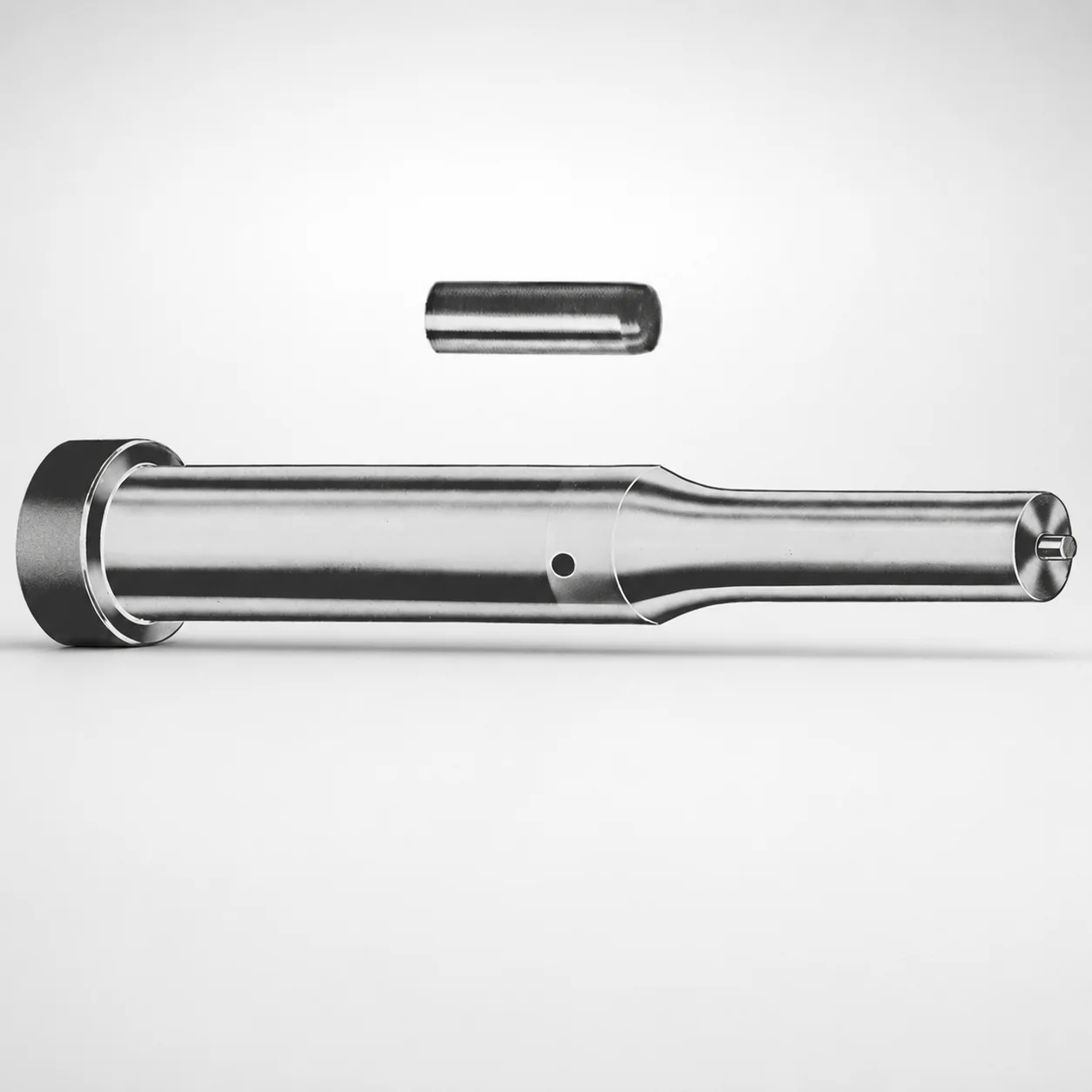
Center Dowel Ejector Punches - Metric, XCDP Coating
Center Dowel Ejector Punches - Metric, XCDP Coating combine a locating dowel punch function with a durable coated surface to support consistent ejection and alignment in production molds. The DAYTON design helps maintain repeatable positioning and smooth punch travel.
- Central ejector punch geometry supports stable mold centering and ejection
- XCDP Coating enhances wear resistance and improves running durability
- Metric configurations support compatibility across standard die and punch layouts
- Suitable for applications requiring precise center guidance during cycling
Specifications
228 configurations available
| Tip shape | D (Shank dia.) (mm) | Jektole group | L1 (Point Length) (mm) | L (Length) (mm) | P Dimension (mm) | W Dimension (mm) | R Dimension (mm) |
|---|---|---|---|---|---|---|---|
| H | 10 | J6M | 19 ~ 25 | 71 ~ 130 | 4 ~ 4.49 | 4 ~ 4.49 | - |
| H | 10 | J6M | 19 ~ 25 | 71 ~ 130 | 4 ~ 4.49 | 4.5 ~ 9.95 | - |
| H | 10 | J6M | 19 ~ 25 | 71 ~ 130 | 4.5 ~ 9.95 | 4 ~ 4.49 | - |
| H | 10 | J6M | 19 ~ 25 | 71 ~ 130 | 4.5 ~ 9.95 | 4.5 ~ 9.95 | - |
| H | 13 | J6M | 19 ~ 25 | 71 ~ 130 | 4 ~ 5.99 | 4 ~ 5.99 | - |
| H | 13 | J6M | 19 ~ 25 | 71 ~ 130 | 4 ~ 5.99 | 6 ~ 12.95 | - |
| H | 13 | J6M | 19 ~ 25 | 71 ~ 130 | 6 ~ 12.95 | 4 ~ 5.99 | - |
| H | 13 | J6M | 19 ~ 25 | 71 ~ 130 | 6 ~ 12.95 | 6 ~ 12.95 | - |
| H | 16 | J9M | 19 ~ 25 | 71 ~ 130 | 6 ~ 7.19 | 6 ~ 7.19 | - |
| H | 16 | J9M | 19 ~ 25 | 71 ~ 130 | 6 ~ 7.19 | 7.2 ~ 15.95 | - |
| H | 16 | J9M | 19 ~ 25 | 71 ~ 130 | 7.2 ~ 15.95 | 6 ~ 7.19 | - |
| H | 16 | J9M | 19 ~ 25 | 71 ~ 130 | 7.2 ~ 15.95 | 7.2 ~ 15.95 | - |
| H | 20 | J9M | 19 ~ 25 | 71 ~ 130 | 6 ~ 7.99 | 6 ~ 7.99 | - |
| H | 20 | J9M | 19 ~ 25 | 71 ~ 130 | 6 ~ 7.99 | 8 ~ 19.95 | - |
| H | 20 | J9M | 19 ~ 25 | 71 ~ 130 | 8 ~ 19.95 | 6 ~ 7.99 | - |
| H | 20 | J9M | 19 ~ 25 | 71 ~ 130 | 8 ~ 19.95 | 8 ~ 19.95 | - |
| H | 25 | J9M | 19 ~ 25 | 71 ~ 130 | 6 ~ 8.99 | 6 ~ 8.99 | - |
| H | 25 | J9M | 19 ~ 25 | 71 ~ 130 | 6 ~ 8.99 | 9 ~ 24.95 | - |
| H | 25 | J9M | 19 ~ 25 | 71 ~ 130 | 9 ~ 24.95 | 6 ~ 8.99 | - |
| H | 25 | J9M | 19 ~ 25 | 71 ~ 130 | 9 ~ 24.95 | 9 ~ 24.95 | - |
| H | 32 | J9M | 25 ~ 30 | 71 ~ 130 | 7.2 ~ 9.99 | 7.2 ~ 9.99 | - |
| H | 32 | J9M | 25 ~ 30 | 71 ~ 130 | 7.2 ~ 9.99 | 10 ~ 31.95 | - |
| H | 32 | J9M | 25 ~ 30 | 71 ~ 130 | 10 ~ 31.95 | 7.2 ~ 9.99 | - |
| H | 32 | J9M | 25 ~ 30 | 71 ~ 130 | 10 ~ 31.95 | 10 ~ 31.95 | - |
| J | 10 | J6M | 19 ~ 25 | 71 ~ 130 | 4 ~ 4.49 | 4 ~ 4.49 | - |
| J | 10 | J6M | 19 ~ 25 | 71 ~ 130 | 4 ~ 4.49 | 4.5 ~ 9.95 | - |
| J | 10 | J6M | 19 ~ 25 | 71 ~ 130 | 4.5 ~ 9.95 | 4 ~ 4.49 | - |
| J | 10 | J6M | 19 ~ 25 | 71 ~ 130 | 4.5 ~ 9.95 | 4.5 ~ 9.95 | - |
| J | 13 | J6M | 19 ~ 25 | 71 ~ 130 | 4 ~ 5.99 | 4 ~ 5.99 | - |
| J | 13 | J6M | 19 ~ 25 | 71 ~ 130 | 4 ~ 5.99 | 6 ~ 12.95 | - |
| J | 13 | J6M | 19 ~ 25 | 71 ~ 130 | 6 ~ 12.95 | 4 ~ 5.99 | - |
| J | 13 | J6M | 19 ~ 25 | 71 ~ 130 | 6 ~ 12.95 | 6 ~ 12.95 | - |
| J | 16 | J9M | 19 ~ 25 | 71 ~ 130 | 6 ~ 7.19 | 6 ~ 7.19 | - |
| J | 16 | J9M | 19 ~ 25 | 71 ~ 130 | 6 ~ 7.19 | 7.2 ~ 15.95 | - |
| J | 16 | J9M | 19 ~ 25 | 71 ~ 130 | 7.2 ~ 15.95 | 6 ~ 7.19 | - |
| J | 16 | J9M | 19 ~ 25 | 71 ~ 130 | 7.2 ~ 15.95 | 7.2 ~ 15.95 | - |
| J | 20 | J9M | 19 ~ 25 | 71 ~ 130 | 6 ~ 7.99 | 6 ~ 7.99 | - |
| J | 20 | J9M | 19 ~ 25 | 71 ~ 130 | 6 ~ 7.99 | 8 ~ 19.95 | - |
| J | 20 | J9M | 19 ~ 25 | 71 ~ 130 | 8 ~ 19.95 | 6 ~ 7.99 | - |
| J | 20 | J9M | 19 ~ 25 | 71 ~ 130 | 8 ~ 19.95 | 8 ~ 19.95 | - |
| J | 25 | J9M | 19 ~ 25 | 71 ~ 130 | 6 ~ 8.99 | 6 ~ 8.99 | - |
| J | 25 | J9M | 19 ~ 25 | 71 ~ 130 | 6 ~ 8.99 | 9 ~ 24.95 | - |
| J | 25 | J9M | 19 ~ 25 | 71 ~ 130 | 9 ~ 24.95 | 6 ~ 8.99 | - |
| J | 25 | J9M | 19 ~ 25 | 71 ~ 130 | 9 ~ 24.95 | 9 ~ 24.95 | - |
| J | 32 | J9M | 25 ~ 30 | 71 ~ 130 | 7.2 ~ 9.99 | 7.2 ~ 9.99 | - |
| J | 32 | J9M | 25 ~ 30 | 71 ~ 130 | 7.2 ~ 9.99 | 10 ~ 31.95 | - |
| J | 32 | J9M | 25 ~ 30 | 71 ~ 130 | 10 ~ 31.95 | 7.2 ~ 9.99 | - |
| J | 32 | J9M | 25 ~ 30 | 71 ~ 130 | 10 ~ 31.95 | 10 ~ 31.95 | - |
| K | 10 | J6M | 19 ~ 25 | 71 ~ 130 | 4 ~ 4.49 | 4 ~ 4.49 | 0.2 ~ 4.975 |
| K | 10 | J6M | 19 ~ 25 | 71 ~ 130 | 4 ~ 4.49 | 4.5 ~ 9.95 | 0.2 ~ 4.975 |
Product Guide
Application Scenarios+
Center dowel ejector punches are used in injection mold toolsets where reliable ejection and tight die alignment are critical. In automotive connector and terminal housing molds, the center-guiding geometry helps maintain stable punch travel during high-cycle ejection, reducing misalignment-driven wear.
In appliance and consumer electronics enclosures, this variant’s XCDP coating supports longer running time by improving surface durability against friction and repeated sliding contact. The fixed-length punch body combined with selectable tip shapes supports consistent fit into standardized die/punch layouts.
- Die alignment reinforcement during cycling for connector and terminal molds
- Durability-focused ejection in high-wear housings using XCDP-coated running surfaces
- Metric compatibility for common die and punch layout standards
Material & Process Details+
The provided specifications focus on geometry and coating rather than a specific steel grade. For this reason, material selection and heat treatment should be confirmed against the supplier’s material/process certificate for the exact series/stock item.
What can be stated from the variant information is that the XCDP coating is selected to enhance wear resistance at the working surface. In dowel-guided ejector applications, this typically improves running durability where repeated contact, sliding friction, and debris exposure accelerate abrasive wear.
- Heat treatment: Verify pre-hardened or quenched-and-tempered state for the underlying punch steel for best toughness vs. hardness balance.
- Hardness & toughness trade-off: Higher surface hardness generally increases wear resistance but can reduce toughness if the base steel is over-hardened.
- Wear resistance focus: XCDP coating targets long-term surface stability during repeated ejection cycles.
Sizing & Selection Guide+
Select the center dowel ejector punch dimensions by matching the die/core geometry and available installation space, using the series’ fixed and variable measures. The overall length L is fixed in the range 71 to 130 mm; choose the length that provides full working engagement without bottoming in the pocket or violating clearance to the stationary plate.
Match the shank diameter D (mm) to the reamed dowel/bushing and guide bore size requirements: 10, 13, 16, 20, 25, or 32 mm. For the front contact/point feature, choose the tip shape (H, J, K, L, N, O, R, V, X, Y, Z) and set the point length L1 to 19–25 mm or 25–30 mm depending on engagement depth.
- Width/step dimensions: P (4–16 mm) and W (4–10 mm) must clear nearby features while maintaining the intended guidance profile.
- Radius/contact control: R is selectable across multiple ranges (0.2–4.975 up to 0.2–15.975 mm), affecting fit and stress distribution.
- Tolerance/fit: Confirm the intended clearance/interference with your die’s guide bore and ejector plate tolerances; for dowel-like guidance, guide alignment is more sensitive to fit errors than general ejector punches.
Frequently Asked Questions
How do I choose the shank diameter D for a center dowel ejector punch with dowel holes?+
For this metric series, the shank diameter D is available as 10, 13, 16, 20, 25, or 32 mm. Select D to match the reamed guide bore/dowel hole size in your ejector system and the ejector plate clearance requirements. Because this part also provides centering guidance, fit consistency matters to avoid misalignment-related wear.
Which point length L1 should I use so the ejector engages correctly without bottoming?+
This series offers L1 (point length) ranges of 19–25 mm and 25–30 mm. Choose the shorter engagement when pocket depth is limited, and the longer range when you need deeper alignment/contact for stable ejection. Confirm against your ejector plate thickness, core/die pocket depth, and allowable clearances for full travel.
What tip shapes are available and how do they affect engagement geometry?+
The tip shape is configurable across H, J, K, L, N, O, R, V, X, Y, Z. Tip shape selection determines how the punch point enters and contacts the mating part, influencing alignment stability and potential wear patterns on the receiving surface. Use the tip shape that matches your die opening and part geometry for consistent center guidance.
What does the XCDP coating add for wear resistance in ejection systems?+
This variant is specified with XCDP coating, which is intended to improve surface durability under repeated sliding and contact during ejection. If your mold runs high cycles or experiences abrasive contamination, the coated surface helps maintain running performance longer than uncoated steel. For exact performance expectations, verify coating thickness and underlying steel condition from the series documentation.
How do I select the fixed overall length L (71–130 mm) during die design?+
The overall length L is fixed within the range 71 to 130 mm for this series. Select the L value that supports full functional engagement throughout the stroke while avoiding bottoming against the receiving pocket or violating spacing to adjacent plates. Recheck travel limits after accounting for coating and any machining allowances in the ejector system.
Related Products

Metric Center Dowel Ejector Punches (SKD11 Equivalent)

Dicoat Treatment SKD11 Steel Center Dowel Ejector Punches - Metric

Center Dowel Ejector Punches - Metric, XCN TiCN Coating

DIN Standard SKD11 Steel Gas Release Single-Stepped Ejector Punches

Center Dowel Ejector Punches with Locating Dowel Hole

DIN Standard TiCN Center Dowel Ejector Punches
Need Custom Specifications?
Our engineering team can help with custom configurations, material selection, and volume pricing.