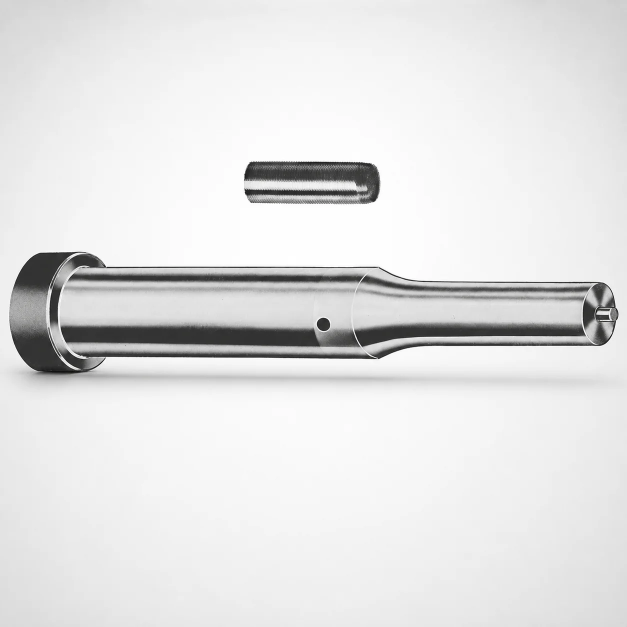
DIN Standard Steel Center Dowel Ejector Punches
Center Dowel ejector punches (Metric) (M2 or A2 steel) are precision guidance ejectors designed for stable centering during die opening and part ejection. Select the tip geometry to match your workpiece and cavity requirements.
- Center dowel guidance improves alignment for consistent ejection repeatability
- M2 or A2 steel construction supports wear resistance in production cycles
- Selectable tip shapes (X, R, K, O, H, L, J, N, V, Y, Z) tailor penetration and contact behavior
- Metric punch design is suited for standard die set assemblies
Specifications
456 configurations available
| Tip shape | Material | D (Shank dia.) (mm) | Jektole group | L1 (Point Length) (mm) | L (Length) (mm) | P Dimension (mm) | W Dimension (mm) | R Dimension (mm) |
|---|---|---|---|---|---|---|---|---|
| H | M2 | 10 | J6M | 19 ~ 25 | 71 ~ 130 | 4 ~ 4.49 | 4 ~ 4.49 | - |
| H | M2 | 10 | J6M | 19 ~ 25 | 71 ~ 130 | 4 ~ 4.49 | 4.5 ~ 9.95 | - |
| H | M2 | 10 | J6M | 19 ~ 25 | 71 ~ 130 | 4.5 ~ 9.95 | 4 ~ 4.49 | - |
| H | M2 | 10 | J6M | 19 ~ 25 | 71 ~ 130 | 4.5 ~ 9.95 | 4.5 ~ 9.95 | - |
| H | A2 | 10 | J6M | 19 ~ 25 | 71 ~ 130 | 4 ~ 4.49 | 4 ~ 4.49 | - |
| H | A2 | 10 | J6M | 19 ~ 25 | 71 ~ 130 | 4 ~ 4.49 | 4.5 ~ 9.95 | - |
| H | A2 | 10 | J6M | 19 ~ 25 | 71 ~ 130 | 4.5 ~ 9.95 | 4 ~ 4.49 | - |
| H | A2 | 10 | J6M | 19 ~ 25 | 71 ~ 130 | 4.5 ~ 9.95 | 4.5 ~ 9.95 | - |
| H | M2 | 13 | J6M | 19 ~ 25 | 71 ~ 130 | 4 ~ 5.99 | 4 ~ 5.99 | - |
| H | M2 | 13 | J6M | 19 ~ 25 | 71 ~ 130 | 4 ~ 5.99 | 6 ~ 12.95 | - |
| H | M2 | 13 | J6M | 19 ~ 25 | 71 ~ 130 | 6 ~ 12.95 | 4 ~ 5.99 | - |
| H | M2 | 13 | J6M | 19 ~ 25 | 71 ~ 130 | 6 ~ 12.95 | 6 ~ 12.95 | - |
| H | A2 | 13 | J6M | 19 ~ 25 | 71 ~ 130 | 4 ~ 5.99 | 4 ~ 5.99 | - |
| H | A2 | 13 | J6M | 19 ~ 25 | 71 ~ 130 | 4 ~ 5.99 | 6 ~ 12.95 | - |
| H | A2 | 13 | J6M | 19 ~ 25 | 71 ~ 130 | 6 ~ 12.95 | 4 ~ 5.99 | - |
| H | A2 | 13 | J6M | 19 ~ 25 | 71 ~ 130 | 6 ~ 12.95 | 6 ~ 12.95 | - |
| H | M2 | 16 | J9M | 19 ~ 25 | 71 ~ 130 | 6 ~ 7.19 | 6 ~ 7.19 | - |
| H | M2 | 16 | J9M | 19 ~ 25 | 71 ~ 130 | 6 ~ 7.19 | 7.2 ~ 15.95 | - |
| H | M2 | 16 | J9M | 19 ~ 25 | 71 ~ 130 | 7.2 ~ 15.95 | 6 ~ 7.19 | - |
| H | M2 | 16 | J9M | 19 ~ 25 | 71 ~ 130 | 7.2 ~ 15.95 | 7.2 ~ 15.95 | - |
| H | A2 | 16 | J9M | 19 ~ 25 | 71 ~ 130 | 6 ~ 7.19 | 6 ~ 7.19 | - |
| H | A2 | 16 | J9M | 19 ~ 25 | 71 ~ 130 | 6 ~ 7.19 | 7.2 ~ 15.95 | - |
| H | A2 | 16 | J9M | 19 ~ 25 | 71 ~ 130 | 7.2 ~ 15.95 | 6 ~ 7.19 | - |
| H | A2 | 16 | J9M | 19 ~ 25 | 71 ~ 130 | 7.2 ~ 15.95 | 7.2 ~ 15.95 | - |
| H | M2 | 20 | J9M | 19 ~ 25 | 71 ~ 130 | 6 ~ 7.99 | 6 ~ 7.99 | - |
| H | M2 | 20 | J9M | 19 ~ 25 | 71 ~ 130 | 6 ~ 7.99 | 8 ~ 19.95 | - |
| H | M2 | 20 | J9M | 19 ~ 25 | 71 ~ 130 | 8 ~ 19.95 | 6 ~ 7.99 | - |
| H | M2 | 20 | J9M | 19 ~ 25 | 71 ~ 130 | 8 ~ 19.95 | 8 ~ 19.95 | - |
| H | A2 | 20 | J9M | 19 ~ 25 | 71 ~ 130 | 6 ~ 7.99 | 6 ~ 7.99 | - |
| H | A2 | 20 | J9M | 19 ~ 25 | 71 ~ 130 | 6 ~ 7.99 | 8 ~ 19.95 | - |
| H | A2 | 20 | J9M | 19 ~ 25 | 71 ~ 130 | 8 ~ 19.95 | 6 ~ 7.99 | - |
| H | A2 | 20 | J9M | 19 ~ 25 | 71 ~ 130 | 8 ~ 19.95 | 8 ~ 19.95 | - |
| H | M2 | 25 | J9M | 19 ~ 25 | 71 ~ 130 | 6 ~ 8.99 | 6 ~ 8.99 | - |
| H | M2 | 25 | J9M | 19 ~ 25 | 71 ~ 130 | 6 ~ 8.99 | 9 ~ 24.95 | - |
| H | M2 | 25 | J9M | 19 ~ 25 | 71 ~ 130 | 9 ~ 24.95 | 6 ~ 8.99 | - |
| H | M2 | 25 | J9M | 19 ~ 25 | 71 ~ 130 | 9 ~ 24.95 | 9 ~ 24.95 | - |
| H | A2 | 25 | J9M | 19 ~ 25 | 71 ~ 130 | 6 ~ 8.99 | 6 ~ 8.99 | - |
| H | A2 | 25 | J9M | 19 ~ 25 | 71 ~ 130 | 6 ~ 8.99 | 9 ~ 24.95 | - |
| H | A2 | 25 | J9M | 19 ~ 25 | 71 ~ 130 | 9 ~ 24.95 | 6 ~ 8.99 | - |
| H | A2 | 25 | J9M | 19 ~ 25 | 71 ~ 130 | 9 ~ 24.95 | 9 ~ 24.95 | - |
| H | M2 | 32 | J9M | 25 ~ 30 | 71 ~ 130 | 7.2 ~ 9.99 | 7.2 ~ 9.99 | - |
| H | M2 | 32 | J9M | 25 ~ 30 | 71 ~ 130 | 7.2 ~ 9.99 | 10 ~ 31.95 | - |
| H | M2 | 32 | J9M | 25 ~ 30 | 71 ~ 130 | 10 ~ 31.95 | 7.2 ~ 9.99 | - |
| H | M2 | 32 | J9M | 25 ~ 30 | 71 ~ 130 | 10 ~ 31.95 | 10 ~ 31.95 | - |
| H | A2 | 32 | J9M | 25 ~ 30 | 71 ~ 130 | 7.2 ~ 9.99 | 7.2 ~ 9.99 | - |
| H | A2 | 32 | J9M | 25 ~ 30 | 71 ~ 130 | 7.2 ~ 9.99 | 10 ~ 31.95 | - |
| H | A2 | 32 | J9M | 25 ~ 30 | 71 ~ 130 | 10 ~ 31.95 | 7.2 ~ 9.99 | - |
| H | A2 | 32 | J9M | 25 ~ 30 | 71 ~ 130 | 10 ~ 31.95 | 10 ~ 31.95 | - |
| J | M2 | 10 | J6M | 19 ~ 25 | 71 ~ 130 | 4 ~ 4.49 | 4 ~ 4.49 | - |
| J | M2 | 10 | J6M | 19 ~ 25 | 71 ~ 130 | 4 ~ 4.49 | 4.5 ~ 9.95 | - |
Product Guide
Application Scenarios+
Center dowel ejector punches are used in die sets and progressive tooling where repeatable part release and stable alignment are critical. During die opening, the center dowel guidance helps maintain coaxial alignment between moving components, reducing mis-ejection and scuffing on the part.
- Automotive and industrial connector housings: use the center guidance effect to keep ejection forces aligned across the cavity, improving consistency over high production cycles.
- Consumer appliance components: selectable tip shapes allow engineers to tailor contact and penetration behavior to thin-wall or textured surfaces, supporting controlled ejection reliability.
- Electronics and enclosure parts: the metric configuration is suited for standard die set assemblies, helping integration with metric tooling dimensions and die layout.
This variant supports controlled guidance through its selectable tip geometry and durable steel construction (M2 or A2), making it well-suited for reliable ejector actuation in production environments.
Material & Process Details+
This series is available in M2 or A2 steel, both commonly specified for precision punch and ejector elements requiring good wear resistance in die operations. In typical practice, M2 is an HSS grade (commonly associated with AISI M2 performance), while A2 is a tool steel (often referenced as AISI A2 equivalent). Material choice is selected based on the balance of wear resistance and toughness needed for your ejection loads and cycle rate.
- M2: favored where higher abrasion/wear resistance is prioritized for longer production runs.
- A2: selected when a different toughness-to-wear balance is preferred for the specific die set conditions.
These steels are typically manufactured as precision-cut punches and then heat treated to achieve the target hardness for punch stability and repeatable guidance performance. Select the material based on expected wear mechanisms and the load profile during ejection.
Sizing & Selection Guide+
Use the specified shank diameter (D) to match the locating and bearing requirements of your die set. Available D values are 10, 13, 16, 20, 25, and 32 mm; choose the diameter that aligns with your ejector plate bore and the center guidance system design.
Overall length is given as L = 71 to 130 mm (range). Match L and the tip engagement using L1 (point length), available in 19–25 mm and 25–30 mm, so the point provides the required contact during ejection without bottoming in the cavity.
- For the specific workpiece interaction, select the tip shape from H, J, K, L, N, O, R, V, X, Y, Z.
- Verify the P (4–16 mm) and W (4–10 mm) dimensions against your tool pocketing/clearance constraints.
- Check the R (0.2–12.475 mm range depending on variant) radius requirement for controlled penetration/contact.
Confirm fit and clearance in the ejector and guide system; while tight guidance is expected, ensure your die layout tolerances can accommodate the chosen punch geometry.
Frequently Asked Questions
Which tip shapes (H, J, K, L, N, O, R, V, X, Y, Z) should I choose for controlled guidance during ejection?+
Select the tip shape to match the part surface condition and desired contact behavior. This series offers multiple selectable geometries (H, J, K, L, N, O, R, V, X, Y, Z) so you can tailor penetration/contact during ejection.
Use R (0.2–12.475 mm range depending on the configuration) together with L1 (19–25 mm or 25–30 mm) to set how deeply the point engages.
How do I choose between M2 and A2 steel for die set ejector reliability?+
This product is available in M2 or A2 steel, both specified for punch/ejector use where wear resistance and guidance stability matter. Choose M2 when your priority is improved wear resistance for longer production cycles.
Choose A2 when you prefer a different toughness-to-wear balance for your specific ejection loads and cycle profile.
What shank diameter D options are available, and how do they relate to die set mounting?+
The available D (shank dia.) values are 10, 13, 16, 20, 25, and 32 mm. Select D to match the bore size and guidance requirements in your ejector plate or die set center guidance arrangement.
Once D is fixed, use the P (4–16 mm) and W (4–10 mm) dimensions to confirm clearance to surrounding die features.
How should I size L and L1 to avoid bottoming and ensure the correct point engagement?+
This series provides L (length) = 71–130 mm and L1 (point length) = 19–25 mm or 25–30 mm. Use L1 to define the contact/engagement depth of the point during ejection.
Then verify that your selected L length provides the required working stroke while preventing the point from bottoming in the cavity.
What R (radius) and P/W dimensions should I verify for specific cavity and clearance constraints?+
Confirm R based on the configuration you select: the radius range is given as 0.2–4.975, 0.2–6.475, 0.2–7.975, 0.2–9.975, 0.2–12.475, and 0.2–15.975 mm depending on the variant. Also verify P (4–16 mm) and W (4–10 mm) against your die pocketing and clearance.
These parameters directly affect the point geometry and contact behavior during ejection.
Related Products

Metric Center Dowel Ejector Punches (SKD11 Equivalent)

Dicoat Treatment SKD11 Steel Center Dowel Ejector Punches - Metric

Center Dowel Ejector Punches - Metric, XCN TiCN Coating

DIN Standard SKD11 Steel Gas Release Single-Stepped Ejector Punches

Center Dowel Ejector Punches with Locating Dowel Hole

DIN Standard TiCN Center Dowel Ejector Punches
Need Custom Specifications?
Our engineering team can help with custom configurations, material selection, and volume pricing.