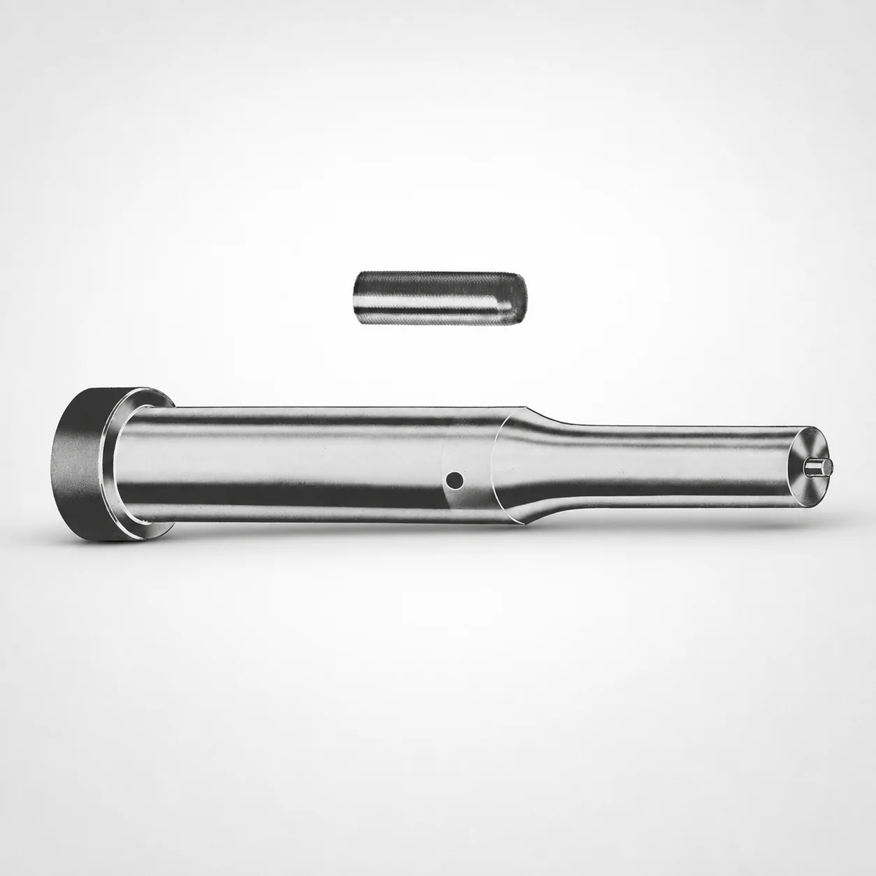
Metric Center Dowel Ejector Punches with XNP Coating
Metric center dowel ejector punches (XNP coating) deliver reliable center guidance and stable ejection in precision die assemblies. The standardized tool format supports quick selection for production and maintenance needs.
- Center dowel geometry improves alignment stability for repeatable ejection
- Surface protection with XNP coating helps resist wear under cyclic die operation
- Compatible with metric press setups using standardized shank and point families for consistent fit
- Used in die applications requiring guided punch ejection and controlled positioning
Specifications
228 configurations available
| Tip shape | D (Shank dia.) (mm) | Jektole group | L1 (Point Length) (mm) | L (Length) (mm) | P Dimension (mm) | W Dimension (mm) | R Dimension (mm) |
|---|---|---|---|---|---|---|---|
| H | 10 | J6M | 19 ~ 25 | 71 ~ 130 | 4 ~ 4.49 | 4 ~ 4.49 | - |
| H | 10 | J6M | 19 ~ 25 | 71 ~ 130 | 4 ~ 4.49 | 4.5 ~ 9.95 | - |
| H | 10 | J6M | 19 ~ 25 | 71 ~ 130 | 4.5 ~ 9.95 | 4 ~ 4.49 | - |
| H | 10 | J6M | 19 ~ 25 | 71 ~ 130 | 4.5 ~ 9.95 | 4.5 ~ 9.95 | - |
| H | 13 | J6M | 19 ~ 25 | 71 ~ 130 | 4 ~ 5.99 | 4 ~ 5.99 | - |
| H | 13 | J6M | 19 ~ 25 | 71 ~ 130 | 4 ~ 5.99 | 6 ~ 12.95 | - |
| H | 13 | J6M | 19 ~ 25 | 71 ~ 130 | 6 ~ 12.95 | 4 ~ 5.99 | - |
| H | 13 | J6M | 19 ~ 25 | 71 ~ 130 | 6 ~ 12.95 | 6 ~ 12.95 | - |
| H | 16 | J9M | 19 ~ 25 | 71 ~ 130 | 6 ~ 7.19 | 6 ~ 7.19 | - |
| H | 16 | J9M | 19 ~ 25 | 71 ~ 130 | 6 ~ 7.19 | 7.2 ~ 15.95 | - |
| H | 16 | J9M | 19 ~ 25 | 71 ~ 130 | 7.2 ~ 15.95 | 6 ~ 7.19 | - |
| H | 16 | J9M | 19 ~ 25 | 71 ~ 130 | 7.2 ~ 15.95 | 7.2 ~ 15.95 | - |
| H | 20 | J9M | 19 ~ 25 | 71 ~ 130 | 6 ~ 7.99 | 6 ~ 7.99 | - |
| H | 20 | J9M | 19 ~ 25 | 71 ~ 130 | 6 ~ 7.99 | 8 ~ 19.95 | - |
| H | 20 | J9M | 19 ~ 25 | 71 ~ 130 | 8 ~ 19.95 | 6 ~ 7.99 | - |
| H | 20 | J9M | 19 ~ 25 | 71 ~ 130 | 8 ~ 19.95 | 8 ~ 19.95 | - |
| H | 25 | J9M | 19 ~ 25 | 71 ~ 130 | 6 ~ 8.99 | 6 ~ 8.99 | - |
| H | 25 | J9M | 19 ~ 25 | 71 ~ 130 | 6 ~ 8.99 | 9 ~ 24.95 | - |
| H | 25 | J9M | 19 ~ 25 | 71 ~ 130 | 9 ~ 24.95 | 6 ~ 8.99 | - |
| H | 25 | J9M | 19 ~ 25 | 71 ~ 130 | 9 ~ 24.95 | 9 ~ 24.95 | - |
| H | 32 | J9M | 25 ~ 30 | 71 ~ 130 | 7.2 ~ 9.99 | 7.2 ~ 9.99 | - |
| H | 32 | J9M | 25 ~ 30 | 71 ~ 130 | 7.2 ~ 9.99 | 10 ~ 31.95 | - |
| H | 32 | J9M | 25 ~ 30 | 71 ~ 130 | 10 ~ 31.95 | 7.2 ~ 9.99 | - |
| H | 32 | J9M | 25 ~ 30 | 71 ~ 130 | 10 ~ 31.95 | 10 ~ 31.95 | - |
| J | 10 | J6M | 19 ~ 25 | 71 ~ 130 | 4 ~ 4.49 | 4 ~ 4.49 | - |
| J | 10 | J6M | 19 ~ 25 | 71 ~ 130 | 4 ~ 4.49 | 4.5 ~ 9.95 | - |
| J | 10 | J6M | 19 ~ 25 | 71 ~ 130 | 4.5 ~ 9.95 | 4 ~ 4.49 | - |
| J | 10 | J6M | 19 ~ 25 | 71 ~ 130 | 4.5 ~ 9.95 | 4.5 ~ 9.95 | - |
| J | 13 | J6M | 19 ~ 25 | 71 ~ 130 | 4 ~ 5.99 | 4 ~ 5.99 | - |
| J | 13 | J6M | 19 ~ 25 | 71 ~ 130 | 4 ~ 5.99 | 6 ~ 12.95 | - |
| J | 13 | J6M | 19 ~ 25 | 71 ~ 130 | 6 ~ 12.95 | 4 ~ 5.99 | - |
| J | 13 | J6M | 19 ~ 25 | 71 ~ 130 | 6 ~ 12.95 | 6 ~ 12.95 | - |
| J | 16 | J9M | 19 ~ 25 | 71 ~ 130 | 6 ~ 7.19 | 6 ~ 7.19 | - |
| J | 16 | J9M | 19 ~ 25 | 71 ~ 130 | 6 ~ 7.19 | 7.2 ~ 15.95 | - |
| J | 16 | J9M | 19 ~ 25 | 71 ~ 130 | 7.2 ~ 15.95 | 6 ~ 7.19 | - |
| J | 16 | J9M | 19 ~ 25 | 71 ~ 130 | 7.2 ~ 15.95 | 7.2 ~ 15.95 | - |
| J | 20 | J9M | 19 ~ 25 | 71 ~ 130 | 6 ~ 7.99 | 6 ~ 7.99 | - |
| J | 20 | J9M | 19 ~ 25 | 71 ~ 130 | 6 ~ 7.99 | 8 ~ 19.95 | - |
| J | 20 | J9M | 19 ~ 25 | 71 ~ 130 | 8 ~ 19.95 | 6 ~ 7.99 | - |
| J | 20 | J9M | 19 ~ 25 | 71 ~ 130 | 8 ~ 19.95 | 8 ~ 19.95 | - |
| J | 25 | J9M | 19 ~ 25 | 71 ~ 130 | 6 ~ 8.99 | 6 ~ 8.99 | - |
| J | 25 | J9M | 19 ~ 25 | 71 ~ 130 | 6 ~ 8.99 | 9 ~ 24.95 | - |
| J | 25 | J9M | 19 ~ 25 | 71 ~ 130 | 9 ~ 24.95 | 6 ~ 8.99 | - |
| J | 25 | J9M | 19 ~ 25 | 71 ~ 130 | 9 ~ 24.95 | 9 ~ 24.95 | - |
| J | 32 | J9M | 25 ~ 30 | 71 ~ 130 | 7.2 ~ 9.99 | 7.2 ~ 9.99 | - |
| J | 32 | J9M | 25 ~ 30 | 71 ~ 130 | 7.2 ~ 9.99 | 10 ~ 31.95 | - |
| J | 32 | J9M | 25 ~ 30 | 71 ~ 130 | 10 ~ 31.95 | 7.2 ~ 9.99 | - |
| J | 32 | J9M | 25 ~ 30 | 71 ~ 130 | 10 ~ 31.95 | 10 ~ 31.95 | - |
| K | 10 | J6M | 19 ~ 25 | 71 ~ 130 | 4 ~ 4.49 | 4 ~ 4.49 | 0.2 ~ 4.975 |
| K | 10 | J6M | 19 ~ 25 | 71 ~ 130 | 4 ~ 4.49 | 4.5 ~ 9.95 | 0.2 ~ 4.975 |
Product Guide
Application Scenarios+
These metric center dowel ejector punches are used in injection-die and press tooling where guided ejection and stable center alignment are critical. The center dowel-style guidance helps maintain repeatable punch positioning, reducing lateral drift during cycling.
In automotive connector and terminal molds, they support consistent ejection in long-run production. The standardized tool format and metric shank diameters (10–32 mm) make it easier to match ejector layouts and replacement parts across multiple cavities.
For electronics housings and small precision parts, the XNP-coated wear surface is suited to applications with frequent cycles and tight positional requirements. Tip shapes (H, J, K, L, N, O, R, V, X, Y, Z) allow engineers to tune point geometry to ejector layout and part geometry.
In die sets requiring controlled punch travel, use the specified point length ranges (L1: 19–25 mm or 25–30 mm) to achieve proper engagement while preserving clearance to surrounding components.
Material & Process Details+
The provided specification set identifies this component by its XNP coating and dowel-ejector geometry, but it does not specify the underlying steel grade, pre-hardening state, or hardness (HRC). For accurate selection, confirm the base material and heat-treatment condition from your technical datasheet before final tooling build-out.
In general terms for ejector punches, hardness and wear resistance are typically balanced against toughness to prevent chipping at the point under intermittent high loading. The XNP coating is intended to improve surface wear performance during cyclic operation, helping maintain effective punch guidance and stable ejection.
- Wear resistance: enhanced by the XNP coating for repetitive die cycling.
- Toughness trade-off: depends on the base steel and heat treatment; without the grade/HRC data, selection must follow the project’s durability targets.
- Heat treatment: not specified here (e.g., quenched & tempered, nitrided, etc.), so verify during procurement.
Sizing & Selection Guide+
Correct sizing starts with matching the shank diameter (D) and overall length envelope to your die set’s ejector bore and support system. Available shank diameters are 10, 13, 16, 20, 25, and 32 mm, while the fixed overall length L is 71–130 mm. Choose L to ensure full stroke clearance and safe retention in the ejector housing.
Next, match the point geometry and engagement depth: select tip shape from H, J, K, L, N, O, R, V, X, Y, Z and choose the point length L1 from 19–25 mm or 25–30 mm based on required part contact without bottoming.
Use the remaining dimensional parameters to ensure interface compatibility with your tooling:
- P (4–16 mm) and W (4–10 mm) should align with your ejector pocket/profile features.
- R radius is selectable across 0.2–4.975, 0.2–6.475, 0.2–7.975, 0.2–9.975, 0.2–12.475, and 0.2–15.975 to control edge contact and stress concentration.
Consider tolerance and fit around the ejector system by following the specific die-standard clearances used for your Jektole group (J6M or J9M).
Frequently Asked Questions
Which shank diameter options (D) are available for metric center dowel ejector punches with XNP coating?+
How do I choose the correct point length (L1) for proper engagement without overstressing the part?+
What tip shapes are supported, and when should different shapes be selected?+
What do P, W, and R dimensions affect in the ejector interface?+
Does this series provide base material and hardness (HRC) specifications?+
Related Products

Metric Center Dowel Ejector Punches (SKD11 Equivalent)

Dicoat Treatment SKD11 Steel Center Dowel Ejector Punches - Metric

Center Dowel Ejector Punches - Metric, XCN TiCN Coating

DIN Standard SKD11 Steel Gas Release Single-Stepped Ejector Punches

Center Dowel Ejector Punches with Locating Dowel Hole

DIN Standard TiCN Center Dowel Ejector Punches
Need Custom Specifications?
Our engineering team can help with custom configurations, material selection, and volume pricing.