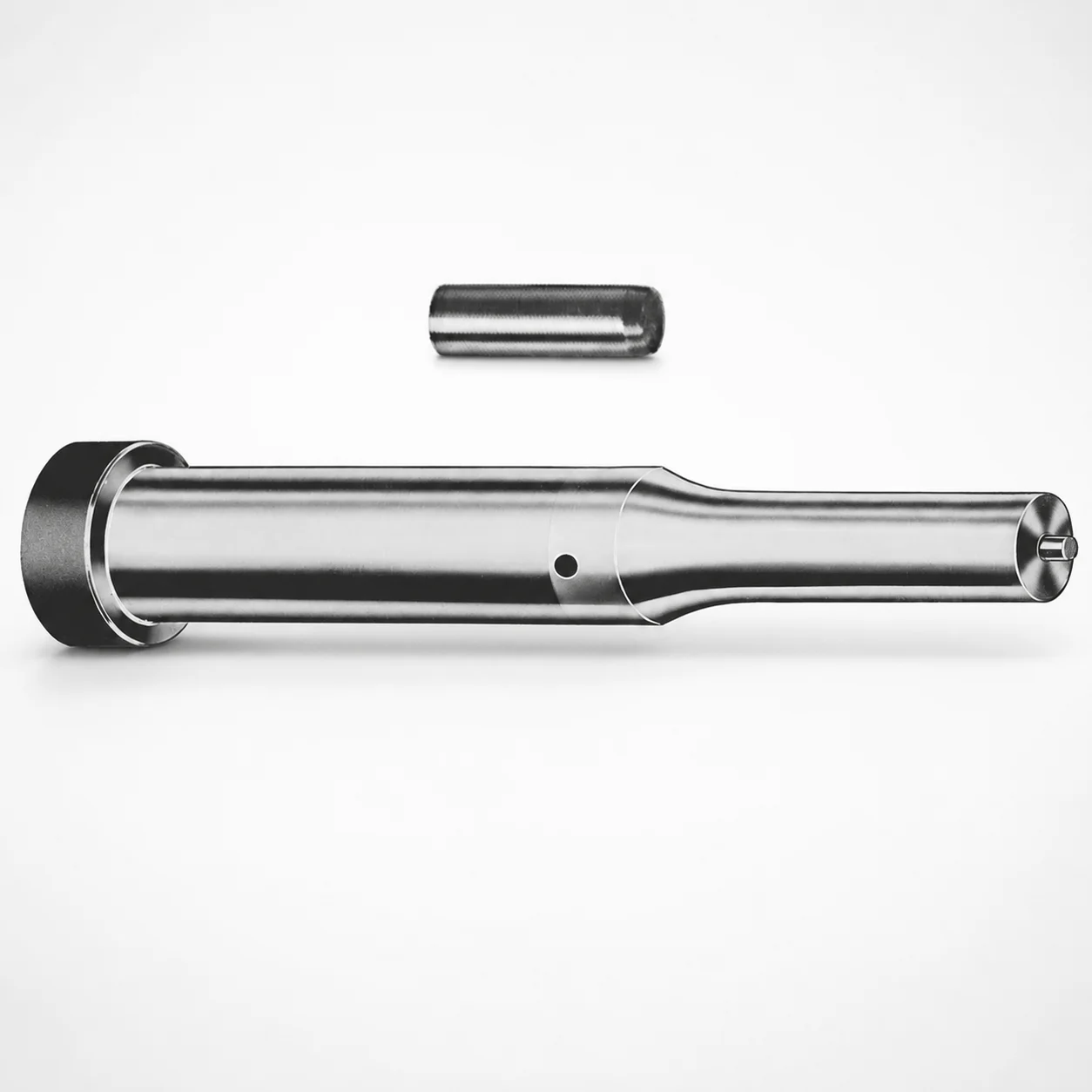
Metric Center Dowel Ejector Punches XNM Coating
Metric Center Dowel Ejector Punches (XNM coating) provide reliable centering and ejection performance in precision tool-and-die assemblies. The XNM surface coating helps support consistent wear resistance across production cycles.
- Centering design for stable ejector punch positioning
- XNM coating for improved durability in demanding molding
- Wide length range supports different press and die layouts
- Available with multiple tip shapes for controlled contacting
Specifications
228 configurations available
| Tip shape | D (Shank dia.) (mm) | Jektole group | L1 (Point Length) (mm) | L (Length) (mm) | P Dimension (mm) | W Dimension (mm) | R Dimension (mm) |
|---|---|---|---|---|---|---|---|
| H | 10 | J6M | 19 ~ 25 | 71 ~ 130 | 4 ~ 4.49 | 4 ~ 4.49 | - |
| H | 10 | J6M | 19 ~ 25 | 71 ~ 130 | 4 ~ 4.49 | 4.5 ~ 9.95 | - |
| H | 10 | J6M | 19 ~ 25 | 71 ~ 130 | 4.5 ~ 9.95 | 4 ~ 4.49 | - |
| H | 10 | J6M | 19 ~ 25 | 71 ~ 130 | 4.5 ~ 9.95 | 4.5 ~ 9.95 | - |
| H | 13 | J6M | 19 ~ 25 | 71 ~ 130 | 4 ~ 5.99 | 4 ~ 5.99 | - |
| H | 13 | J6M | 19 ~ 25 | 71 ~ 130 | 4 ~ 5.99 | 6 ~ 12.95 | - |
| H | 13 | J6M | 19 ~ 25 | 71 ~ 130 | 6 ~ 12.95 | 4 ~ 5.99 | - |
| H | 13 | J6M | 19 ~ 25 | 71 ~ 130 | 6 ~ 12.95 | 6 ~ 12.95 | - |
| H | 16 | J9M | 19 ~ 25 | 71 ~ 130 | 6 ~ 7.19 | 6 ~ 7.19 | - |
| H | 16 | J9M | 19 ~ 25 | 71 ~ 130 | 6 ~ 7.19 | 7.2 ~ 15.95 | - |
| H | 16 | J9M | 19 ~ 25 | 71 ~ 130 | 7.2 ~ 15.95 | 6 ~ 7.19 | - |
| H | 16 | J9M | 19 ~ 25 | 71 ~ 130 | 7.2 ~ 15.95 | 7.2 ~ 15.95 | - |
| H | 20 | J9M | 19 ~ 25 | 71 ~ 130 | 6 ~ 7.99 | 6 ~ 7.99 | - |
| H | 20 | J9M | 19 ~ 25 | 71 ~ 130 | 6 ~ 7.99 | 8 ~ 19.95 | - |
| H | 20 | J9M | 19 ~ 25 | 71 ~ 130 | 8 ~ 19.95 | 6 ~ 7.99 | - |
| H | 20 | J9M | 19 ~ 25 | 71 ~ 130 | 8 ~ 19.95 | 8 ~ 19.95 | - |
| H | 25 | J9M | 19 ~ 25 | 71 ~ 130 | 6 ~ 8.99 | 6 ~ 8.99 | - |
| H | 25 | J9M | 19 ~ 25 | 71 ~ 130 | 6 ~ 8.99 | 9 ~ 24.95 | - |
| H | 25 | J9M | 19 ~ 25 | 71 ~ 130 | 9 ~ 24.95 | 6 ~ 8.99 | - |
| H | 25 | J9M | 19 ~ 25 | 71 ~ 130 | 9 ~ 24.95 | 9 ~ 24.95 | - |
| H | 32 | J9M | 25 ~ 30 | 71 ~ 130 | 7.2 ~ 9.99 | 7.2 ~ 9.99 | - |
| H | 32 | J9M | 25 ~ 30 | 71 ~ 130 | 7.2 ~ 9.99 | 10 ~ 31.95 | - |
| H | 32 | J9M | 25 ~ 30 | 71 ~ 130 | 10 ~ 31.95 | 7.2 ~ 9.99 | - |
| H | 32 | J9M | 25 ~ 30 | 71 ~ 130 | 10 ~ 31.95 | 10 ~ 31.95 | - |
| J | 10 | J6M | 19 ~ 25 | 71 ~ 130 | 4 ~ 4.49 | 4 ~ 4.49 | - |
| J | 10 | J6M | 19 ~ 25 | 71 ~ 130 | 4 ~ 4.49 | 4.5 ~ 9.95 | - |
| J | 10 | J6M | 19 ~ 25 | 71 ~ 130 | 4.5 ~ 9.95 | 4 ~ 4.49 | - |
| J | 10 | J6M | 19 ~ 25 | 71 ~ 130 | 4.5 ~ 9.95 | 4.5 ~ 9.95 | - |
| J | 13 | J6M | 19 ~ 25 | 71 ~ 130 | 4 ~ 5.99 | 4 ~ 5.99 | - |
| J | 13 | J6M | 19 ~ 25 | 71 ~ 130 | 4 ~ 5.99 | 6 ~ 12.95 | - |
| J | 13 | J6M | 19 ~ 25 | 71 ~ 130 | 6 ~ 12.95 | 4 ~ 5.99 | - |
| J | 13 | J6M | 19 ~ 25 | 71 ~ 130 | 6 ~ 12.95 | 6 ~ 12.95 | - |
| J | 16 | J9M | 19 ~ 25 | 71 ~ 130 | 6 ~ 7.19 | 6 ~ 7.19 | - |
| J | 16 | J9M | 19 ~ 25 | 71 ~ 130 | 6 ~ 7.19 | 7.2 ~ 15.95 | - |
| J | 16 | J9M | 19 ~ 25 | 71 ~ 130 | 7.2 ~ 15.95 | 6 ~ 7.19 | - |
| J | 16 | J9M | 19 ~ 25 | 71 ~ 130 | 7.2 ~ 15.95 | 7.2 ~ 15.95 | - |
| J | 20 | J9M | 19 ~ 25 | 71 ~ 130 | 6 ~ 7.99 | 6 ~ 7.99 | - |
| J | 20 | J9M | 19 ~ 25 | 71 ~ 130 | 6 ~ 7.99 | 8 ~ 19.95 | - |
| J | 20 | J9M | 19 ~ 25 | 71 ~ 130 | 8 ~ 19.95 | 6 ~ 7.99 | - |
| J | 20 | J9M | 19 ~ 25 | 71 ~ 130 | 8 ~ 19.95 | 8 ~ 19.95 | - |
| J | 25 | J9M | 19 ~ 25 | 71 ~ 130 | 6 ~ 8.99 | 6 ~ 8.99 | - |
| J | 25 | J9M | 19 ~ 25 | 71 ~ 130 | 6 ~ 8.99 | 9 ~ 24.95 | - |
| J | 25 | J9M | 19 ~ 25 | 71 ~ 130 | 9 ~ 24.95 | 6 ~ 8.99 | - |
| J | 25 | J9M | 19 ~ 25 | 71 ~ 130 | 9 ~ 24.95 | 9 ~ 24.95 | - |
| J | 32 | J9M | 25 ~ 30 | 71 ~ 130 | 7.2 ~ 9.99 | 7.2 ~ 9.99 | - |
| J | 32 | J9M | 25 ~ 30 | 71 ~ 130 | 7.2 ~ 9.99 | 10 ~ 31.95 | - |
| J | 32 | J9M | 25 ~ 30 | 71 ~ 130 | 10 ~ 31.95 | 7.2 ~ 9.99 | - |
| J | 32 | J9M | 25 ~ 30 | 71 ~ 130 | 10 ~ 31.95 | 10 ~ 31.95 | - |
| K | 10 | J6M | 19 ~ 25 | 71 ~ 130 | 4 ~ 4.49 | 4 ~ 4.49 | 0.2 ~ 4.975 |
| K | 10 | J6M | 19 ~ 25 | 71 ~ 130 | 4 ~ 4.49 | 4.5 ~ 9.95 | 0.2 ~ 4.975 |
Product Guide
Application Scenarios+
Metric center dowel ejector punches are used in precision injection mold tool-and-die assemblies where stable alignment between the ejector system and the die cavity is critical. Their centering geometry helps maintain consistent punch positioning during high-cycle opening and closing, reducing the risk of uneven contact at the ejector face.
- Automotive and appliance connector molds: In long-run production, the ejector punch can see repeated sliding and point loading; the XNM surface coating is suited to improve wear consistency over production cycles.
- Thin-wall consumer parts and housings: When the ejector system must initiate controlled ejection without disturbing the part, the variety of tip shapes (H, J, K, L, N, O, R, V, X, Y, Z) supports tailored contacting behavior.
- High-mix tooling with frequent die changes: The broad overall length range (L = 71 to 130 mm) supports different press and die stack layouts while maintaining center-guided ejector performance.
Material & Process Details+
The provided specification emphasizes the XNM surface coating as the key durability feature for this ejector punch variant. While the exact steel grade and heat-treatment condition are not listed in the input data, XNM coatings are selected for improved wear resistance under repeated sliding contact and cyclic mechanical loading.
- Wear vs. toughness trade-off: Coated surfaces typically enhance abrasion resistance, but the underlying steel toughness still governs impact tolerance during ejection events.
- Manufacturing process (typical for coated punches): The shank and tip are machined to the required geometry, followed by surface preparation and coating deposition to achieve consistent tribological performance.
- Hardness (HRC): Not specified in the provided data, so hardness and tempering targets cannot be stated for this exact item.
Sizing & Selection Guide+
Select the ejector punch dimensions by matching the shank diameter, overall length, and point geometry to the ejector plate clearance and the cavity/core penetration depth. This product supports a fixed overall length range L = 71 ~ 130 mm, with a variable point length L1 = 19 ~ 25 mm or 25 ~ 30 mm.
- Shank diameter (D): Choose one of 10, 13, 16, 20, 25, 32 mm to fit your guide bore/retainer diameter while maintaining alignment.
- Point/tip profile: Select the required tip shape (H, J, K, L, N, O, R, V, X, Y, Z) and point dimensions P (4 ~ 16 mm), W (4 ~ 10 mm), and R from the available ranges (0.2 ~ 4.975 up to 0.2 ~ 15.975 depending on configuration).
- Clearance & tolerance: Ensure the chosen D and overall L provide safe clearance through ejector stroke while preserving center guidance. Use your mold’s drawing tolerances for fit in the punch guide/plate; the provided data lists dimension ranges, not specific tolerance classes.
Frequently Asked Questions
Which tip shape options (H/J/K/L/N/O/R/V/X/Y/Z) should I choose for controlled contacting in an ejector system?+
This series offers multiple tip shapes (H, J, K, L, N, O, R, V, X, Y, Z) so you can match the contact behavior to the part surface and ejection mechanism. Use the tip shape that provides the desired contact area and load transfer for your part geometry. Pair the chosen tip shape with the available point length L1 (19~25 or 25~30 mm) to keep contact timing aligned with your ejector stroke.
How do I match the shank diameter D and overall length L (71–130 mm) to the ejector plate and die layout?+
Select D (10, 13, 16, 20, 25, 32 mm) based on your guide bore/retainer diameter for proper centering and stable movement. Then choose L within 71 ~ 130 mm so the punch reaches the required penetration depth without bottoming out. Because the input data provides ranges but not tolerance grades, verify clearances against your mold drawing before finalizing the build.
What coating role does XNM play, and what does “better wear resistance” mean for repeated injection cycles?+
The XNM coating is specified as a surface treatment intended to support consistent wear resistance across production cycles. In service, ejector punches experience repeated sliding and localized contact pressure at the tip; the coating helps maintain surface performance under that cyclic loading. The exact coating thickness and base material hardness (HRC) are not provided in the available data, so those values must be confirmed from the supplier spec sheet if needed.
How do P (4–16 mm), W (4–10 mm), and R (0.2–up to 15.975 mm) affect the point geometry for ejection?+
This series includes variable geometry parameters: P = 4 ~ 16 mm, W = 4 ~ 10 mm, and R with multiple upper limits (e.g., 0.2 ~ 4.975 up to 0.2 ~ 15.975). These dimensions determine the detailed contacting profile at the punch tip and therefore influence contact area, stress concentration, and part surface risk during ejection. Choose them to balance firm enough contact for reliable release with reduced marking for the target material/part finish.
What are the Jektole group options (J6M, J9M), and do they change how the punch should be selected?+
The data lists Jektole group options as J6M and J9M. In practice, these groupings typically correspond to compatibility with specific mold system interfaces and guide standards within the vendor’s catalog. To ensure fit, select the group that matches your existing ejector layout and confirm that the chosen D, L, and point geometry align with your cavity/core and ejector plate clearances.
Related Products

Metric Center Dowel Ejector Punches (SKD11 Equivalent)

Dicoat Treatment SKD11 Steel Center Dowel Ejector Punches - Metric

Center Dowel Ejector Punches - Metric, XCN TiCN Coating

DIN Standard SKD11 Steel Gas Release Single-Stepped Ejector Punches

Center Dowel Ejector Punches with Locating Dowel Hole

DIN Standard TiCN Center Dowel Ejector Punches
Need Custom Specifications?
Our engineering team can help with custom configurations, material selection, and volume pricing.