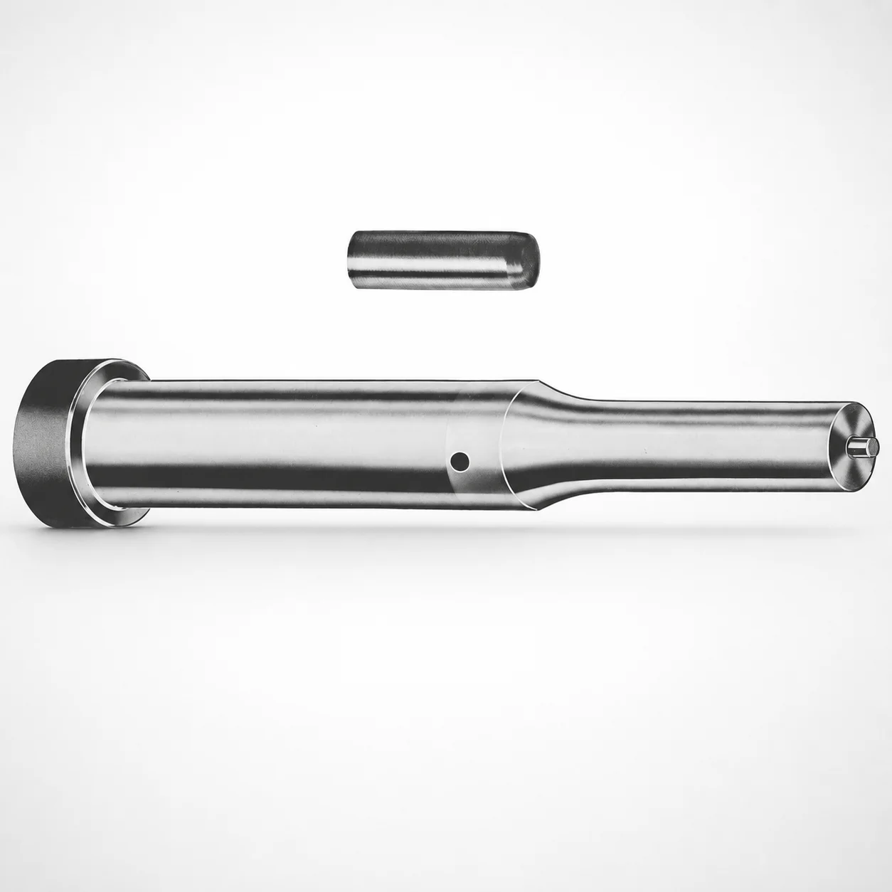
Metric Center Dowel Ejector Punches | XN DayTride Coating
Metric center dowel ejector punches (XN DayTride® coating) are designed to support precise guiding and consistent ejection in production dies. The center dowel geometry helps maintain alignment under repeated cycles.
- Built-in center dowel design supports reliable guiding during ejection cycles
- XN DayTride® coating improves wear resistance for long service life
- Available tip shapes (X, R, K, O, H, L, J, N, V, Y, Z) for process matching
- For metric die applications requiring stable locating and repeatable punch performance
Specifications
228 configurations available
| Tip shape | D (Shank dia.) (mm) | Jektole group | L1 (Point Length) (mm) | L (Length) (mm) | P Dimension (mm) | W Dimension (mm) | R Dimension (mm) |
|---|---|---|---|---|---|---|---|
| H | 10 | J6M | 19 ~ 25 | 71 ~ 130 | 4 ~ 4.49 | 4 ~ 4.49 | - |
| H | 10 | J6M | 19 ~ 25 | 71 ~ 130 | 4 ~ 4.49 | 4.5 ~ 9.95 | - |
| H | 10 | J6M | 19 ~ 25 | 71 ~ 130 | 4.5 ~ 9.95 | 4 ~ 4.49 | - |
| H | 10 | J6M | 19 ~ 25 | 71 ~ 130 | 4.5 ~ 9.95 | 4.5 ~ 9.95 | - |
| H | 13 | J6M | 19 ~ 25 | 71 ~ 130 | 4 ~ 5.99 | 4 ~ 5.99 | - |
| H | 13 | J6M | 19 ~ 25 | 71 ~ 130 | 4 ~ 5.99 | 6 ~ 12.95 | - |
| H | 13 | J6M | 19 ~ 25 | 71 ~ 130 | 6 ~ 12.95 | 4 ~ 5.99 | - |
| H | 13 | J6M | 19 ~ 25 | 71 ~ 130 | 6 ~ 12.95 | 6 ~ 12.95 | - |
| H | 16 | J9M | 19 ~ 25 | 71 ~ 130 | 6 ~ 7.19 | 6 ~ 7.19 | - |
| H | 16 | J9M | 19 ~ 25 | 71 ~ 130 | 6 ~ 7.19 | 7.2 ~ 15.95 | - |
| H | 16 | J9M | 19 ~ 25 | 71 ~ 130 | 7.2 ~ 15.95 | 6 ~ 7.19 | - |
| H | 16 | J9M | 19 ~ 25 | 71 ~ 130 | 7.2 ~ 15.95 | 7.2 ~ 15.95 | - |
| H | 20 | J9M | 19 ~ 25 | 71 ~ 130 | 6 ~ 7.99 | 6 ~ 7.99 | - |
| H | 20 | J9M | 19 ~ 25 | 71 ~ 130 | 6 ~ 7.99 | 8 ~ 19.95 | - |
| H | 20 | J9M | 19 ~ 25 | 71 ~ 130 | 8 ~ 19.95 | 6 ~ 7.99 | - |
| H | 20 | J9M | 19 ~ 25 | 71 ~ 130 | 8 ~ 19.95 | 8 ~ 19.95 | - |
| H | 25 | J9M | 19 ~ 25 | 71 ~ 130 | 6 ~ 8.99 | 6 ~ 8.99 | - |
| H | 25 | J9M | 19 ~ 25 | 71 ~ 130 | 6 ~ 8.99 | 9 ~ 24.95 | - |
| H | 25 | J9M | 19 ~ 25 | 71 ~ 130 | 9 ~ 24.95 | 6 ~ 8.99 | - |
| H | 25 | J9M | 19 ~ 25 | 71 ~ 130 | 9 ~ 24.95 | 9 ~ 24.95 | - |
| H | 32 | J9M | 25 ~ 30 | 71 ~ 130 | 7.2 ~ 9.99 | 7.2 ~ 9.99 | - |
| H | 32 | J9M | 25 ~ 30 | 71 ~ 130 | 7.2 ~ 9.99 | 10 ~ 31.95 | - |
| H | 32 | J9M | 25 ~ 30 | 71 ~ 130 | 10 ~ 31.95 | 7.2 ~ 9.99 | - |
| H | 32 | J9M | 25 ~ 30 | 71 ~ 130 | 10 ~ 31.95 | 10 ~ 31.95 | - |
| J | 10 | J6M | 19 ~ 25 | 71 ~ 130 | 4 ~ 4.49 | 4 ~ 4.49 | - |
| J | 10 | J6M | 19 ~ 25 | 71 ~ 130 | 4 ~ 4.49 | 4.5 ~ 9.95 | - |
| J | 10 | J6M | 19 ~ 25 | 71 ~ 130 | 4.5 ~ 9.95 | 4 ~ 4.49 | - |
| J | 10 | J6M | 19 ~ 25 | 71 ~ 130 | 4.5 ~ 9.95 | 4.5 ~ 9.95 | - |
| J | 13 | J6M | 19 ~ 25 | 71 ~ 130 | 4 ~ 5.99 | 4 ~ 5.99 | - |
| J | 13 | J6M | 19 ~ 25 | 71 ~ 130 | 4 ~ 5.99 | 6 ~ 12.95 | - |
| J | 13 | J6M | 19 ~ 25 | 71 ~ 130 | 6 ~ 12.95 | 4 ~ 5.99 | - |
| J | 13 | J6M | 19 ~ 25 | 71 ~ 130 | 6 ~ 12.95 | 6 ~ 12.95 | - |
| J | 16 | J9M | 19 ~ 25 | 71 ~ 130 | 6 ~ 7.19 | 6 ~ 7.19 | - |
| J | 16 | J9M | 19 ~ 25 | 71 ~ 130 | 6 ~ 7.19 | 7.2 ~ 15.95 | - |
| J | 16 | J9M | 19 ~ 25 | 71 ~ 130 | 7.2 ~ 15.95 | 6 ~ 7.19 | - |
| J | 16 | J9M | 19 ~ 25 | 71 ~ 130 | 7.2 ~ 15.95 | 7.2 ~ 15.95 | - |
| J | 20 | J9M | 19 ~ 25 | 71 ~ 130 | 6 ~ 7.99 | 6 ~ 7.99 | - |
| J | 20 | J9M | 19 ~ 25 | 71 ~ 130 | 6 ~ 7.99 | 8 ~ 19.95 | - |
| J | 20 | J9M | 19 ~ 25 | 71 ~ 130 | 8 ~ 19.95 | 6 ~ 7.99 | - |
| J | 20 | J9M | 19 ~ 25 | 71 ~ 130 | 8 ~ 19.95 | 8 ~ 19.95 | - |
| J | 25 | J9M | 19 ~ 25 | 71 ~ 130 | 6 ~ 8.99 | 6 ~ 8.99 | - |
| J | 25 | J9M | 19 ~ 25 | 71 ~ 130 | 6 ~ 8.99 | 9 ~ 24.95 | - |
| J | 25 | J9M | 19 ~ 25 | 71 ~ 130 | 9 ~ 24.95 | 6 ~ 8.99 | - |
| J | 25 | J9M | 19 ~ 25 | 71 ~ 130 | 9 ~ 24.95 | 9 ~ 24.95 | - |
| J | 32 | J9M | 25 ~ 30 | 71 ~ 130 | 7.2 ~ 9.99 | 7.2 ~ 9.99 | - |
| J | 32 | J9M | 25 ~ 30 | 71 ~ 130 | 7.2 ~ 9.99 | 10 ~ 31.95 | - |
| J | 32 | J9M | 25 ~ 30 | 71 ~ 130 | 10 ~ 31.95 | 7.2 ~ 9.99 | - |
| J | 32 | J9M | 25 ~ 30 | 71 ~ 130 | 10 ~ 31.95 | 10 ~ 31.95 | - |
| K | 10 | J6M | 19 ~ 25 | 71 ~ 130 | 4 ~ 4.49 | 4 ~ 4.49 | 0.2 ~ 4.975 |
| K | 10 | J6M | 19 ~ 25 | 71 ~ 130 | 4 ~ 4.49 | 4.5 ~ 9.95 | 0.2 ~ 4.975 |
Product Guide
Application Scenarios+
Metric center dowel ejector punches are used inside injection mold tooling where punch-to-plate alignment must remain stable across high-cycle ejection. The built-in center dowel geometry helps maintain concentric guiding of the ejector punch during repeated strokes, reducing side load and improving consistency of part release.
- Automotive connector and housing molds: suited for die cavities that require repeatable ejection timing and accurate alignment, especially when the ejector system sees continuous duty cycles. The center dowel guidance and XN DayTride® wear-focused coating help preserve performance under friction and abrasive contact.
- Consumer electronics enclosure molds: for thin-wall or precision inserts where punch wandering can create surface defects. Selecting the appropriate tip shape (X, R, K, O, H, L, J, N, V, Y, Z) allows matching contact geometry to the gate/parting load profile.
- Medical device housings: for stringent dimensional stability requirements in production runs. The guiding function supports smooth ejection while the coating supports long service life in abrasive wear environments.
Material & Process Details+
Material and heat-treatment details are not provided in the supplied specifications for this center dowel ejector punch series. However, the product variant explicitly features an XN DayTride® coating, which is intended to improve wear resistance at the sliding/impact interface during ejection.
- Coating role: reduces abrasive wear and helps maintain punch dimensions and guiding performance over long production cycles.
- Wear vs. toughness trade-off: coated tool surfaces generally improve surface durability, while bulk toughness is primarily governed by the underlying base steel (not specified here).
- Material comparison: no alternate steel grades are listed for this item, so hardness (HRC) and specific heat-treatment state (e.g., quench & temper, nitriding) cannot be stated from the provided data.
Sizing & Selection Guide+
Selection starts by matching the shank diameter D and the overall L to your ejector system clearance and stroke geometry. This series offers D = 10, 13, 16, 20, 25, or 32 mm, and a fixed L = 71 to 130 mm range depending on the selected configuration.
- Point engagement: choose L1 (Point Length) as 19–25 mm or 25–30 mm to control how far the punch tip enters the part or insert region.
- Tip geometry: select the correct tip shape (H, J, K, L, N, O, R, V, X, Y, Z) to match the required contact area and load path.
- Dowel-related clearance features: confirm P = 4–16 mm and W = 4–10 mm against your punch guide/bushing and locating design constraints.
- Radius/edge profile: ensure the specified R dimension (multiple ranges: 0.2–4.975 up to 0.2–15.975 depending on build) matches the desired contact smoothness.
Tolerance and fit values are not specified in the provided data; engineers should apply their standard ejector/punch fit and verify clearance against the guide and ejector plate machining limits.
Frequently Asked Questions
How do I choose the correct shank diameter (D) for a center dowel ejector punch in a metric mold?+
Select D from the available options: 10, 13, 16, 20, 25, or 32 mm. D should match the bore diameter and guide support features of your ejector plate and related bushings. After selecting D, verify that the fixed overall L (71–130 mm) fits your available space for the punch stroke path.
Which point length (L1) should I use to control punch penetration during ejection?+
This series provides L1 (Point Length) in two ranges: 19–25 mm and 25–30 mm. Use the shorter range to limit penetration where part clearance is tight, and the longer range when deeper engagement is needed for reliable release. Confirm that L1 does not conflict with the cavity depth and any inserts.
What tip shapes are available and when would I select a specific geometry (e.g., R vs. X vs. O)?+
Available tip shapes are H, J, K, L, N, O, R, V, X, Y, Z. Choose the geometry to match the intended contact profile on the part or insert to manage local stress and avoid scuffing. When switching between parts with different surfaces or radii, re-evaluate tip shape alongside R dimension ranges.
How do P and W dimensions affect compatibility with the punch guide and locating features?+
This series lists P = 4–16 mm and W = 4–10 mm as variable dimensions. These should be checked against your guide/bushing design and the locating features in the ejector system to ensure correct seating and alignment with the center dowel arrangement. Because fit tolerances are not provided, engineers must validate clearances with their standard machining tolerances.
Does the XN DayTride® coating change how I should spec for wear and service life?+
The product variant includes XN DayTride® coating, which is intended to improve wear resistance in sliding/impact areas during ejection. While the coating supports longer service life by reducing wear, the underlying base material grade, hardness (HRC), and specific heat-treatment state are not included in the provided data. If your design is sensitive to surface hardness, confirm base steel specs with the supplier and then select the proper tip shape to control contact conditions.
Related Products

Metric Center Dowel Ejector Punches (SKD11 Equivalent)

Dicoat Treatment SKD11 Steel Center Dowel Ejector Punches - Metric

Center Dowel Ejector Punches - Metric, XCN TiCN Coating

DIN Standard SKD11 Steel Gas Release Single-Stepped Ejector Punches

Center Dowel Ejector Punches with Locating Dowel Hole

DIN Standard TiCN Center Dowel Ejector Punches
Need Custom Specifications?
Our engineering team can help with custom configurations, material selection, and volume pricing.